%%{init: {'theme':'base', 'themeVariables': {'primaryColor':'#2C3E50','primaryTextColor':'#fff','primaryBorderColor':'#16A085','lineColor':'#16A085','secondaryColor':'#E67E22','tertiaryColor':'#ECF0F1','fontSize':'13px'}}}%%
flowchart TD
    Start[Start Sensor Implementation]

    Research[1. Research Phase<br/>Datasheet review<br/>Select libraries]
    Wire[2. Hardware Setup<br/>Breadboard wiring<br/>Power connections]
    Basic[3. Basic Test<br/>Verify communication<br/>Read raw values]
    Calibrate[4. Calibration<br/>Two-point calibration<br/>Offset correction]
    Filter[5. Data Processing<br/>Noise filtering<br/>Validation checks]
    Deploy[6. Deployment<br/>Production code<br/>Error handling]

    Check1{Communication<br/>OK?}
    Check2{Values<br/>accurate?}
    Check3{Stable<br/>readings?}

    Debug1[DEBUG: Check wiring<br/>Verify voltage levels<br/>Test I2C scan]
    Debug2[DEBUG: Calibrate sensor<br/>Check environmental factors<br/>Review datasheet specs]
    Debug3[DEBUG: Add filtering<br/>Check power supply<br/>Shield from noise]

    Start --> Research
    Research --> Wire
    Wire --> Basic
    Basic --> Check1
    Check1 -->|No| Debug1
    Debug1 --> Wire
    Check1 -->|Yes| Calibrate
    Calibrate --> Check2
    Check2 -->|No| Debug2
    Debug2 --> Calibrate
    Check2 -->|Yes| Filter
    Filter --> Check3
    Check3 -->|No| Debug3
    Debug3 --> Filter
    Check3 -->|Yes| Deploy

    style Start fill:#2C3E50,stroke:#16A085,color:#fff
    style Deploy fill:#27ae60,stroke:#2C3E50,color:#fff
    style Research fill:#16A085,stroke:#2C3E50,color:#fff
    style Wire fill:#16A085,stroke:#2C3E50,color:#fff
    style Basic fill:#16A085,stroke:#2C3E50,color:#fff
    style Calibrate fill:#16A085,stroke:#2C3E50,color:#fff
    style Filter fill:#16A085,stroke:#2C3E50,color:#fff
    style Check1 fill:#E67E22,stroke:#2C3E50,color:#fff
    style Check2 fill:#E67E22,stroke:#2C3E50,color:#fff
    style Check3 fill:#E67E22,stroke:#2C3E50,color:#fff
    style Debug1 fill:#c0392b,stroke:#2C3E50,color:#fff
    style Debug2 fill:#c0392b,stroke:#2C3E50,color:#fff
    style Debug3 fill:#c0392b,stroke:#2C3E50,color:#fff
531 Temperature Sensor Labs
531.1 Learning Objectives
By the end of this chapter, you will be able to:
- Interface DS18B20 sensors: Configure 1-Wire bus and read multiple temperature sensors on a single pin
- Understand thermocouple fundamentals: Learn how thermocouples generate temperature-dependent voltages
- Compare humidity sensors: Evaluate capacitive, resistive, and thermal conductivity sensing methods
- Implement temperature monitoring: Build robust temperature acquisition systems with proper wiring and pull-up resistors
531.2 Prerequisites

Required Knowledge:
- Sensor Fundamentals - Sensor types and characteristics
- Electronics Basics - Circuit fundamentals
- Sensor Circuits - Signal conditioning
Hardware Requirements:
- Arduino Uno/Nano or ESP32 development board
- Breadboard and jumper wires
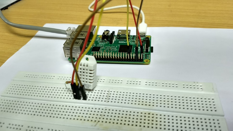
- DS18B20 temperature sensor (or DHT22)
- 4.7kOhm pull-up resistor (for DS18B20)
- USB cable for programming
Software Requirements:
- Arduino IDE installed and configured
- Required libraries: OneWire, DallasTemperature
Skills Checklist:
TipFor Beginners: Temperature Sensor Basics
Temperature sensors are among the most common sensors in IoT applications. Here’s what makes them special:
Why Temperature Matters in IoT: - HVAC systems adjust heating/cooling based on readings - Cold chain monitoring ensures vaccine/food safety - Industrial processes require precise temperature control - Weather stations track environmental conditions
Common Temperature Sensor Types: | Sensor | Interface | Accuracy | Best For | |——–|———–|———-|———-| | DS18B20 | 1-Wire digital | +/-0.5C | Multi-sensor chains | | DHT22 | Proprietary digital | +/-0.5C | Temp + humidity combo | | Thermistor | Analog | +/-1C | Low cost, fast response | | Thermocouple | Analog | +/-2C | Extreme temperatures |
Tip: DS18B20 is great for beginners because each sensor has a unique ID, allowing multiple sensors on one wire!
531.3 Temperature Sensors Overview
%%{init: {'theme':'base', 'themeVariables': {'primaryColor':'#2C3E50','primaryTextColor':'#fff','primaryBorderColor':'#16A085','lineColor':'#16A085','secondaryColor':'#E67E22','tertiaryColor':'#ECF0F1','fontSize':'10px'}}}%%
flowchart TB
    subgraph before["BEFORE POWER ON"]
        B1["Check VCC voltage<br/>3.3V or 5V?"]
        B2["Verify GND connection<br/>Common ground?"]
        B3["Data pin correct GPIO?<br/>Check pinout diagram"]
        B4["Pull-up resistor<br/>4.7k for I2C/1-Wire"]
    end

    subgraph first["FIRST TEST"]
        F1["I2C Scan<br/>Address detected?"]
        F2["Raw value reading<br/>Non-zero response?"]
        F3["Known reference<br/>Ice water = 0C"]
    end

    subgraph debug["COMMON FAILURES"]
        D1["No response -> Check wiring/address"]
        D2["Wrong values -> Check voltage/timing"]
        D3["Unstable -> Add filtering/decoupling"]
        D4["Drift -> Calibrate/thermal isolation"]
    end

    before --> first
    first --> debug

    style before fill:#E8F5E9,stroke:#16A085
    style first fill:#E3F2FD,stroke:#2C3E50
    style debug fill:#FFF3E0,stroke:#E67E22
531.4 DS18B20 (1-Wire Digital Temperature)
NoteAcademic Resource: DHT Temperature/Humidity Sensor Setup (NPTEL)
Source: NPTEL Internet of Things Course, IIT Kharagpur - The DHT22 is one of the most common temperature/humidity sensors for IoT projects due to its low cost, ease of use, and adequate accuracy for most applications.
Specifications:
- Temperature Range: -55C to 125C (+/-0.5C accuracy)
- Interface: 1-Wire (multiple sensors on one pin)
- Resolution: 9-12 bit configurable
- Power: 3.0-5.5V, parasitic power mode available
ESP32 Implementation:
#include <OneWire.h>
#include <DallasTemperature.h>

#define ONE_WIRE_BUS 4  // GPIO4

OneWire oneWire(ONE_WIRE_BUS);
DallasTemperature sensors(&oneWire);

// Store number of devices
int numberOfDevices;
DeviceAddress tempDeviceAddress;

void setup() {
  Serial.begin(115200);

  sensors.begin();

  // Get number of devices on the bus
  numberOfDevices = sensors.getDeviceCount();
  Serial.print("Found ");
  Serial.print(numberOfDevices);
  Serial.println(" temperature sensors");

  // Print addresses
  for(int i=0; i<numberOfDevices; i++) {
    if(sensors.getAddress(tempDeviceAddress, i)) {
      Serial.print("Sensor ");
      Serial.print(i);
      Serial.print(" Address: ");
      printAddress(tempDeviceAddress);
      Serial.println();
    }
  }
}

void loop() {
  sensors.requestTemperatures();

  for(int i=0; i<numberOfDevices; i++) {
    if(sensors.getAddress(tempDeviceAddress, i)) {
      float tempC = sensors.getTempC(tempDeviceAddress);

      Serial.print("Sensor ");
      Serial.print(i);
      Serial.print(": ");
      Serial.print(tempC);
      Serial.println("C");
    }
  }

  delay(1000);
}

void printAddress(DeviceAddress deviceAddress) {
  for (uint8_t i = 0; i < 8; i++) {
    if (deviceAddress[i] < 16) Serial.print("0");
    Serial.print(deviceAddress[i], HEX);
  }
}
TipLearning Points: DS18B20
Key Advantages: - Unique 64-bit address: Each sensor has factory-programmed ID - Multi-sensor bus: Connect dozens of sensors on single GPIO pin - Digital output: No ADC needed, noise-immune over long cables - Parasitic power: Can operate with only 2 wires (data + ground)
Common Issues and Fixes: | Problem | Likely Cause | Solution | |———|————–|———-| | No sensors found | Missing pull-up | Add 4.7kOhm between data and VCC | | Reads 85C | Conversion incomplete | Wait 750ms after requestTemperatures() | | Reads -127C | CRC error | Check wiring, reduce cable length | | Intermittent | Long cables | Use lower resolution (9-bit = 93ms) |
531.5 Thermocouple-Based Temperature Sensors
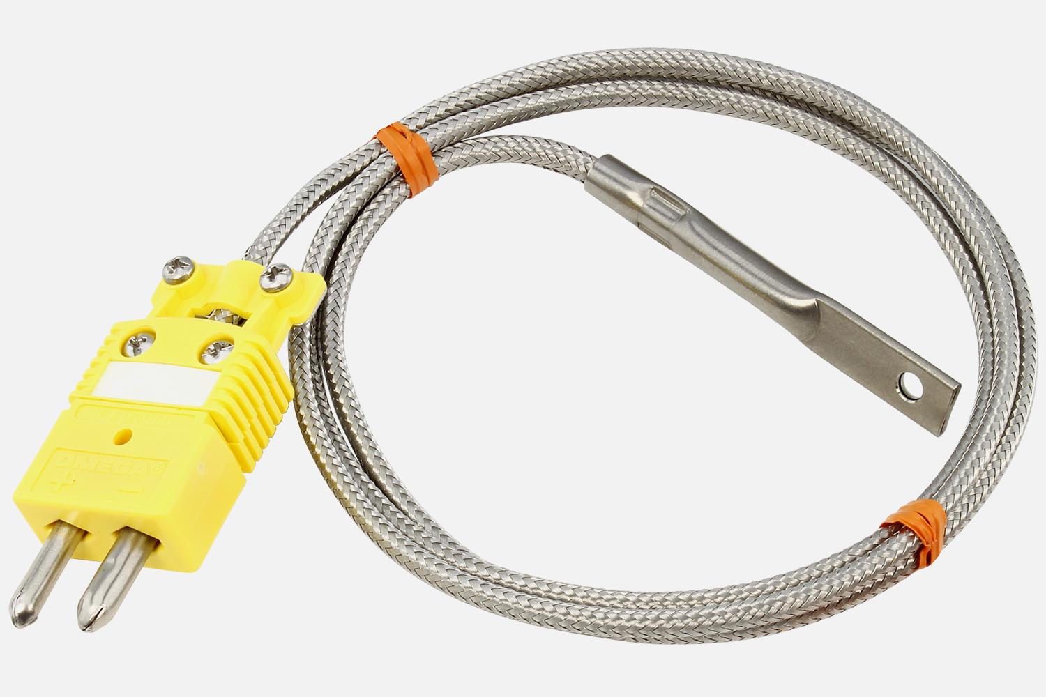
How Thermocouples Work:
Thermocouples generate a small voltage (microvolts) based on the temperature difference between two junctions of dissimilar metals. This is called the Seebeck effect.
Thermocouple Types:
| Type | Metals | Range | Typical Use |
|---|---|---|---|
| K | Chromel/Alumel | -200 to 1250C | General purpose |
| J | Iron/Constantan | -40 to 750C | Industrial |
| T | Copper/Constantan | -200 to 350C | Low temperature |
| E | Chromel/Constantan | -200 to 900C | Highest output |
Cold Junction Compensation:
Thermocouples measure temperature difference, not absolute temperature. You need a reference junction (cold junction) at known temperature. Most thermocouple amplifier ICs (MAX31855, MAX6675) include built-in cold junction compensation.
531.6 Humidity Sensors Comparison
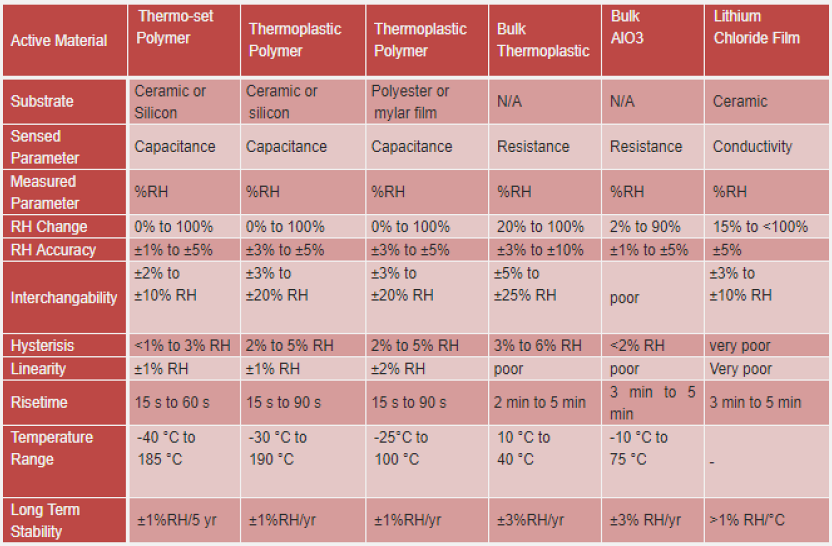
DHT22 (AM2302) Implementation:
The DHT22 combines temperature and humidity sensing in one package, making it popular for environmental monitoring.
Key DHT22 Characteristics:
- Temperature: -40 to 80C (+/-0.5C)
- Humidity: 0-100% RH (+/-2-5%)
- Sampling rate: 0.5 Hz (one reading every 2 seconds)
- Interface: Proprietary single-wire protocol
WarningDHT22 Timing Requirement
The DHT22 requires a minimum 2-second interval between readings. Reading faster causes the sensor to return stale data or errors. Always include delay(2000) in your loop when using DHT sensors.
void loop() {
  float temp = dht.readTemperature();
  float humidity = dht.readHumidity();

  if (isnan(temp) || isnan(humidity)) {
    Serial.println("Failed to read from DHT!");
  }

  delay(2000);  // CRITICAL: Wait at least 2 seconds
}
531.7 Knowledge Check
Question 1: What is the minimum time required between DHT22 sensor readings?
Explanation: The DHT22 sensor requires at least 2 seconds between readings for the internal measurement cycle to complete. Reading faster will result in errors or repeated values because the sensor hasn’t finished converting temperature/humidity measurements.
Question 2: A DS18B20 sensor consistently reads 85.0C immediately after power-on. What does this indicate?
Explanation: 85.0C (0x0550) is the DS18B20’s power-on reset value, indicating “conversion not ready.” The sensor needs up to 750ms (at 12-bit resolution) to complete temperature conversion. Always wait for conversion to complete before reading.
531.8 Summary
This chapter covered temperature sensor implementation fundamentals:
- DS18B20 1-Wire sensors enable multi-sensor networks on a single GPIO pin with unique addressing
- DHT22 sensors provide combined temperature and humidity but require 2-second minimum intervals
- Thermocouples measure extreme temperatures using the Seebeck effect with cold junction compensation
- Proper pull-up resistors (4.7kOhm for 1-Wire, 10kOhm for DHT) ensure reliable communication
- Common error values (85C, -127C, NaN) indicate specific failure modes that guide debugging
531.9 What’s Next?
Now that you understand temperature sensors, continue to learn about motion and environmental sensors including accelerometers, gyroscopes, and barometric pressure sensors.
531.10 See Also
- Sensor Fundamentals - Comprehensive sensor characteristics
- Sensor Calibration Lab - Hands-on calibration techniques
- Best Practices & Labs - Implementation guidelines