%%{init: {'theme': 'base', 'themeVariables': { 'primaryColor': '#2C3E50', 'primaryTextColor': '#fff', 'primaryBorderColor': '#16A085', 'lineColor': '#16A085', 'secondaryColor': '#E67E22', 'tertiaryColor': '#7F8C8D'}}}%%
graph LR
    subgraph Symbols["Common Network Device Symbols"]
        R["Router<br/>(Routes between networks)"]
        S["Switch<br/>(Connects devices in LAN)"]
        FW["Firewall<br/>(Security boundary)"]
        AP["Access Point<br/>(Wireless connectivity)"]
        SRV["Server<br/>(Provides services)"]
        PC["Computer<br/>(End device)"]
        IOT["IoT Device<br/>(Sensor/Actuator)"]
    end

    style R fill:#2C3E50,stroke:#16A085,stroke-width:2px,color:#fff
    style S fill:#16A085,stroke:#2C3E50,stroke-width:2px,color:#fff
    style FW fill:#E67E22,stroke:#2C3E50,stroke-width:2px,color:#fff
    style AP fill:#2C3E50,stroke:#16A085,stroke-width:2px,color:#fff
    style SRV fill:#16A085,stroke:#2C3E50,stroke-width:2px,color:#fff
    style PC fill:#E67E22,stroke:#2C3E50,stroke-width:2px,color:#fff
    style IOT fill:#2C3E50,stroke:#16A085,stroke-width:2px,color:#fff
    style Symbols fill:#f0f0f0,stroke:#7F8C8D,stroke-width:2px
774 Network Topology Types
774.1 Learning Objectives
By the end of this section, you will be able to:
- Identify Topology Types: Recognize star, bus, ring, full mesh, and partial mesh configurations
- Understand Topology Characteristics: Know the advantages and disadvantages of each type
- Apply Topologies to IoT: Select appropriate topology for different IoT scenarios
- Read Network Diagrams: Interpret logical topology symbols and conventions
774.2 Prerequisites
- Topologies Introduction: Understanding of physical vs logical topology concepts
774.3 Logical Topologies Overview
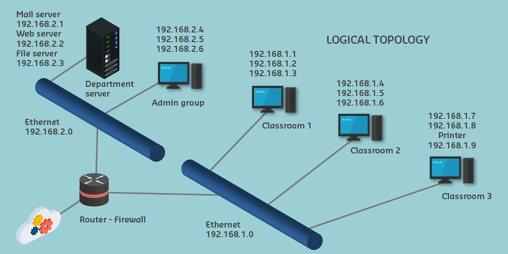
774.3.1 Purpose and Features
Logical topology explains network operation, not physical layout.
Key features: 1. Symbols - Simplified device icons 2. Flow lines - Represent connections and data flow 3. Layout - Hierarchical arrangement 4. Labels and addresses - Device identification and IP information
774.3.2 Network Device Symbols
Common symbols (Cisco-style):
Note: No official international standards for network symbols (unlike electrical symbols). Cisco conventions are widely adopted.
774.3.3 Link Symbols
| Symbol | Meaning |
|---|---|
| Solid line | Ethernet (wired) |
| Dashed line | Wireless connection |
| Wavy line | Serial connection |
| Lightning bolt | High-speed link |
| Thick line | Multiple connections bundled |
774.3.4 Hierarchical Layout
Best practice: Arrange logical diagrams hierarchically
%%{init: {'theme': 'base', 'themeVariables': { 'primaryColor': '#2C3E50', 'primaryTextColor': '#fff', 'primaryBorderColor': '#16A085', 'lineColor': '#16A085', 'secondaryColor': '#E67E22', 'tertiaryColor': '#7F8C8D'}}}%%
graph TB
    Internet([Internet])

    subgraph Core["Core Layer (Top)"]
        R1[Router/Gateway]
    end

    subgraph Distribution["Distribution Layer"]
        SW1[Switch 1]
        SW2[Switch 2]
    end

    subgraph Access["Access Layer (Bottom)"]
        D1[Device 1]
        D2[Device 2]
        D3[Device 3]
        D4[Device 4]
        D5[Device 5]
        D6[Device 6]
    end

    Internet <--> R1
    R1 <--> SW1
    R1 <--> SW2
    SW1 <--> D1
    SW1 <--> D2
    SW1 <--> D3
    SW2 <--> D4
    SW2 <--> D5
    SW2 <--> D6

    style Internet fill:#7F8C8D,stroke:#2C3E50,stroke-width:2px,color:#fff
    style R1 fill:#2C3E50,stroke:#16A085,stroke-width:3px,color:#fff
    style SW1 fill:#16A085,stroke:#2C3E50,stroke-width:2px,color:#fff
    style SW2 fill:#16A085,stroke:#2C3E50,stroke-width:2px,color:#fff
    style Core fill:#f8f9fa,stroke:#2C3E50,stroke-width:2px
    style Distribution fill:#f8f9fa,stroke:#16A085,stroke-width:2px
    style Access fill:#f8f9fa,stroke:#E67E22,stroke-width:2px
Layout principles: - Core devices at top/center - Connected devices radiating outward - Two-way data flow understood - Hierarchy shows message routing
774.4 Star Topology

Configuration: All devices connect to central node (switch/hub)
%%{init: {'theme': 'base', 'themeVariables': { 'primaryColor': '#2C3E50', 'primaryTextColor': '#fff', 'primaryBorderColor': '#16A085', 'lineColor': '#16A085', 'secondaryColor': '#E67E22', 'tertiaryColor': '#7F8C8D'}}}%%
graph TD
    Hub[Central Hub/Switch]

    D1[Device 1]
    D2[Device 2]
    D3[Device 3]
    D4[Device 4]
    D5[Device 5]
    D6[Device 6]

    Hub --- D1
    Hub --- D2
    Hub --- D3
    Hub --- D4
    Hub --- D5
    Hub --- D6

    style Hub fill:#E67E22,stroke:#2C3E50,stroke-width:4px,color:#fff
    style D1 fill:#16A085,stroke:#2C3E50,stroke-width:2px,color:#fff
    style D2 fill:#16A085,stroke:#2C3E50,stroke-width:2px,color:#fff
    style D3 fill:#16A085,stroke:#2C3E50,stroke-width:2px,color:#fff
    style D4 fill:#16A085,stroke:#2C3E50,stroke-width:2px,color:#fff
    style D5 fill:#16A085,stroke:#2C3E50,stroke-width:2px,color:#fff
    style D6 fill:#16A085,stroke:#2C3E50,stroke-width:2px,color:#fff
Characteristics: - Easy to install and manage - Failure of one device doesn’t affect others - Easy to add/remove devices - Central node is single point of failure - Requires more cable than bus topology
IoT Use Cases: - Smart home with central hub - Office sensors connected to gateway - Industrial sensors to local controller
774.5 Extended Star Topology

Configuration: Multiple star topologies interconnected
%%{init: {'theme': 'base', 'themeVariables': { 'primaryColor': '#2C3E50', 'primaryTextColor': '#fff', 'primaryBorderColor': '#16A085', 'lineColor': '#16A085', 'secondaryColor': '#E67E22', 'tertiaryColor': '#7F8C8D'}}}%%
graph TD
    Core[Core Switch]

    SW1[Switch 1]
    SW2[Switch 2]
    SW3[Switch 3]

    D1[Device 1]
    D2[Device 2]
    D3[Device 3]
    D4[Device 4]
    D5[Device 5]
    D6[Device 6]
    D7[Device 7]
    D8[Device 8]
    D9[Device 9]

    Core --- SW1
    Core --- SW2
    Core --- SW3

    SW1 --- D1
    SW1 --- D2
    SW1 --- D3

    SW2 --- D4
    SW2 --- D5
    SW2 --- D6

    SW3 --- D7
    SW3 --- D8
    SW3 --- D9

    style Core fill:#2C3E50,stroke:#16A085,stroke-width:4px,color:#fff
    style SW1 fill:#E67E22,stroke:#2C3E50,stroke-width:3px,color:#fff
    style SW2 fill:#E67E22,stroke:#2C3E50,stroke-width:3px,color:#fff
    style SW3 fill:#E67E22,stroke:#2C3E50,stroke-width:3px,color:#fff
    style D1 fill:#16A085,stroke:#2C3E50,stroke-width:2px,color:#fff
    style D2 fill:#16A085,stroke:#2C3E50,stroke-width:2px,color:#fff
    style D3 fill:#16A085,stroke:#2C3E50,stroke-width:2px,color:#fff
    style D4 fill:#16A085,stroke:#2C3E50,stroke-width:2px,color:#fff
    style D5 fill:#16A085,stroke:#2C3E50,stroke-width:2px,color:#fff
    style D6 fill:#16A085,stroke:#2C3E50,stroke-width:2px,color:#fff
    style D7 fill:#16A085,stroke:#2C3E50,stroke-width:2px,color:#fff
    style D8 fill:#16A085,stroke:#2C3E50,stroke-width:2px,color:#fff
    style D9 fill:#16A085,stroke:#2C3E50,stroke-width:2px,color:#fff
Characteristics: - Highly scalable - Fault tolerance (one switch fails, others continue) - Hierarchical management - More complex configuration
IoT Use Cases: - Multi-building campus network - Large industrial facility - Smart city infrastructure
774.6 Bus Topology

Configuration: All devices share common medium (bus)
%%{init: {'theme': 'base', 'themeVariables': { 'primaryColor': '#2C3E50', 'primaryTextColor': '#fff', 'primaryBorderColor': '#16A085', 'lineColor': '#16A085', 'secondaryColor': '#E67E22', 'tertiaryColor': '#7F8C8D'}}}%%
graph LR
    T1[Terminator]
    D1[Device 1]
    D2[Device 2]
    D3[Device 3]
    D4[Device 4]
    D5[Device 5]
    T2[Terminator]

    T1 ===|Bus Cable| D1
    D1 === D2
    D2 === D3
    D3 === D4
    D4 === D5
    D5 ===|Bus Cable| T2

    style T1 fill:#E67E22,stroke:#2C3E50,stroke-width:2px,color:#fff
    style T2 fill:#E67E22,stroke:#2C3E50,stroke-width:2px,color:#fff
    style D1 fill:#16A085,stroke:#2C3E50,stroke-width:2px,color:#fff
    style D2 fill:#16A085,stroke:#2C3E50,stroke-width:2px,color:#fff
    style D3 fill:#16A085,stroke:#2C3E50,stroke-width:2px,color:#fff
    style D4 fill:#16A085,stroke:#2C3E50,stroke-width:2px,color:#fff
    style D5 fill:#16A085,stroke:#2C3E50,stroke-width:2px,color:#fff
Characteristics: - Minimal cable required - Easy to extend - Well-suited for temporary networks - Bus failure affects entire network - Difficult to troubleshoot - Performance degrades with many devices
IoT Use Cases: - I2C sensor bus (on same PCB) - CAN bus in vehicles - Legacy building automation systems
774.7 Ring Topology

Configuration: Devices connected in circular sequence
%%{init: {'theme': 'base', 'themeVariables': { 'primaryColor': '#2C3E50', 'primaryTextColor': '#fff', 'primaryBorderColor': '#16A085', 'lineColor': '#16A085', 'secondaryColor': '#E67E22', 'tertiaryColor': '#7F8C8D'}}}%%
graph LR
    D1[Device 1]
    D2[Device 2]
    D3[Device 3]
    D4[Device 4]
    D5[Device 5]
    D6[Device 6]

    D1 -->|Token Flow| D2
    D2 --> D3
    D3 --> D4
    D4 --> D5
    D5 --> D6
    D6 --> D1

    style D1 fill:#16A085,stroke:#2C3E50,stroke-width:2px,color:#fff
    style D2 fill:#16A085,stroke:#2C3E50,stroke-width:2px,color:#fff
    style D3 fill:#16A085,stroke:#2C3E50,stroke-width:2px,color:#fff
    style D4 fill:#16A085,stroke:#2C3E50,stroke-width:2px,color:#fff
    style D5 fill:#16A085,stroke:#2C3E50,stroke-width:2px,color:#fff
    style D6 fill:#16A085,stroke:#2C3E50,stroke-width:2px,color:#fff
Characteristics: - Equal access for all devices - Predictable performance - No collisions (token-based) - Single device failure can break ring - Difficult to reconfigure
IoT Use Cases: - Fiber optic industrial networks - FDDI (legacy) - Token Ring (legacy)
Modern variant: Dual ring for fault tolerance
774.8 Full Mesh Topology

Configuration: Every device directly connected to every other device
%%{init: {'theme': 'base', 'themeVariables': { 'primaryColor': '#2C3E50', 'primaryTextColor': '#fff', 'primaryBorderColor': '#16A085', 'lineColor': '#16A085', 'secondaryColor': '#E67E22', 'tertiaryColor': '#7F8C8D'}}}%%
graph TD
    D1[Device 1]
    D2[Device 2]
    D3[Device 3]
    D4[Device 4]
    D5[Device 5]

    D1 --- D2
    D1 --- D3
    D1 --- D4
    D1 --- D5
    D2 --- D3
    D2 --- D4
    D2 --- D5
    D3 --- D4
    D3 --- D5
    D4 --- D5

    style D1 fill:#16A085,stroke:#2C3E50,stroke-width:2px,color:#fff
    style D2 fill:#16A085,stroke:#2C3E50,stroke-width:2px,color:#fff
    style D3 fill:#16A085,stroke:#2C3E50,stroke-width:2px,color:#fff
    style D4 fill:#16A085,stroke:#2C3E50,stroke-width:2px,color:#fff
    style D5 fill:#16A085,stroke:#2C3E50,stroke-width:2px,color:#fff
Characteristics: - Maximum redundancy - No single point of failure - High fault tolerance - Multiple simultaneous connections - Expensive (many connections) - Complex configuration - Number of connections = n(n-1)/2
IoT Use Cases: - Zigbee mesh networks (automatic organization) - Critical infrastructure monitoring - Emergency communication systems
Example: 5 devices = 10 connections, 10 devices = 45 connections!
774.9 Partial Mesh Topology

Configuration: Some devices fully connected, others not
%%{init: {'theme': 'base', 'themeVariables': { 'primaryColor': '#2C3E50', 'primaryTextColor': '#fff', 'primaryBorderColor': '#16A085', 'lineColor': '#16A085', 'secondaryColor': '#E67E22', 'tertiaryColor': '#7F8C8D'}}}%%
graph TD
    D1[Device 1]
    D2[Device 2]
    D3[Device 3]
    D4[Device 4]
    D5[Device 5]
    D6[Device 6]

    D1 --- D2
    D1 --- D3
    D2 --- D3
    D2 --- D4
    D3 --- D5
    D4 --- D5
    D4 --- D6
    D5 --- D6
    D1 -.->|Redundant Path| D4
    D2 -.->|Redundant Path| D6

    style D1 fill:#16A085,stroke:#2C3E50,stroke-width:2px,color:#fff
    style D2 fill:#16A085,stroke:#2C3E50,stroke-width:2px,color:#fff
    style D3 fill:#16A085,stroke:#2C3E50,stroke-width:2px,color:#fff
    style D4 fill:#16A085,stroke:#2C3E50,stroke-width:2px,color:#fff
    style D5 fill:#16A085,stroke:#2C3E50,stroke-width:2px,color:#fff
    style D6 fill:#16A085,stroke:#2C3E50,stroke-width:2px,color:#fff
Characteristics: - Balance between cost and redundancy - Critical paths have backup routes - Less expensive than full mesh - Not all devices have direct paths
IoT Use Cases: - Hybrid sensor networks - Multi-site WAN connections - Smart city infrastructure
774.10 Topology Selection Decision Tree
%%{init: {'theme': 'base', 'themeVariables': { 'primaryColor': '#E67E22', 'primaryTextColor': '#fff', 'primaryBorderColor': '#2C3E50', 'lineColor': '#16A085', 'secondaryColor': '#16A085', 'tertiaryColor': '#2C3E50', 'fontSize': '12px'}}}%%
flowchart TD
    Start["What are your<br/>IoT requirements?"]

    Q1{"Is reliability<br/>critical?<br/>(Mission-critical?)"}
    Q2{"Need self-healing<br/>without manual<br/>intervention?"}
    Q3{"Battery-powered<br/>sensors?"}
    Q4{"High bandwidth<br/>needed?<br/>(Video, audio)"}
    Q5{"More than<br/>30 devices?"}
    Q6{"Legacy system<br/>compatibility?"}

    Mesh["Full/Partial<br/>MESH<br/>Zigbee, Thread"]
    Star["STAR<br/>Wi-Fi, LoRaWAN"]
    Hybrid["HYBRID<br/>Star + Mesh"]
    Bus["BUS<br/>CAN, I2C"]
    Tree["TREE<br/>Extended Star"]

    Ex1["Smart factory<br/>Industrial IoT"]
    Ex2["Smart home<br/>Small office"]
    Ex3["Mixed deployment<br/>Video + sensors"]
    Ex4["Automotive<br/>Building automation"]
    Ex5["Campus network<br/>Multi-building"]

    Start --> Q1
    Q1 -->|"Yes"| Q2
    Q1 -->|"No"| Q4

    Q2 -->|"Yes"| Mesh
    Q2 -->|"No, manual OK"| Q5

    Q5 -->|"Yes"| Tree
    Q5 -->|"No"| Star

    Q4 -->|"Yes"| Q3
    Q4 -->|"No"| Q6

    Q3 -->|"Yes"| Hybrid
    Q3 -->|"No"| Star

    Q6 -->|"Yes"| Bus
    Q6 -->|"No"| Star

    Mesh --> Ex1
    Star --> Ex2
    Hybrid --> Ex3
    Bus --> Ex4
    Tree --> Ex5

    style Start fill:#2C3E50,stroke:#2C3E50,color:#fff
    style Q1 fill:#E67E22,stroke:#2C3E50,color:#fff
    style Q2 fill:#E67E22,stroke:#2C3E50,color:#fff
    style Q3 fill:#E67E22,stroke:#2C3E50,color:#fff
    style Q4 fill:#E67E22,stroke:#2C3E50,color:#fff
    style Q5 fill:#E67E22,stroke:#2C3E50,color:#fff
    style Q6 fill:#E67E22,stroke:#2C3E50,color:#fff
    style Mesh fill:#16A085,stroke:#2C3E50,color:#fff
    style Star fill:#16A085,stroke:#2C3E50,color:#fff
    style Hybrid fill:#16A085,stroke:#2C3E50,color:#fff
    style Bus fill:#16A085,stroke:#2C3E50,color:#fff
    style Tree fill:#16A085,stroke:#2C3E50,color:#fff
    style Ex1 fill:#7F8C8D,stroke:#2C3E50,color:#fff
    style Ex2 fill:#7F8C8D,stroke:#2C3E50,color:#fff
    style Ex3 fill:#7F8C8D,stroke:#2C3E50,color:#fff
    style Ex4 fill:#7F8C8D,stroke:#2C3E50,color:#fff
    style Ex5 fill:#7F8C8D,stroke:#2C3E50,color:#fff
774.11 Topology Scalability Comparison
%%{init: {'theme': 'base', 'themeVariables': { 'primaryColor': '#E67E22', 'primaryTextColor': '#fff', 'primaryBorderColor': '#2C3E50', 'lineColor': '#16A085', 'secondaryColor': '#16A085', 'tertiaryColor': '#2C3E50', 'fontSize': '11px'}}}%%
graph TB
    subgraph Scale["Scalability: 10 vs 50 vs 100 Nodes"]
        subgraph S10["10 Nodes"]
            Star10["Star: 10 links<br/>Cost: $"]
            Mesh10["Full Mesh: 45 links<br/>Cost: $$"]
            Bus10["Bus: 1 segment<br/>Cost: $"]
        end

        subgraph S50["50 Nodes"]
            Star50["Star: 50 links<br/>Cost: $$"]
            Mesh50["Full Mesh: 1,225 links<br/>Cost: $$$$$ IMPRACTICAL"]
            Bus50["Bus: 1 segment<br/>Performance: DEGRADED"]
        end

        subgraph S100["100 Nodes"]
            Star100["Star: 100 links<br/>May need hierarchy"]
            Mesh100["Full Mesh: 4,950 links<br/>IMPOSSIBLE"]
            Bus100["Bus: 1 segment<br/>UNUSABLE"]
        end
    end

    subgraph Formula["Connection Formula"]
        StarF["Star: n connections<br/>O(n) - Linear"]
        MeshF["Full Mesh: n(n-1)/2<br/>O(n²) - Quadratic"]
        PartialF["Partial Mesh: ~2-3n<br/>O(n) - Linear"]
    end

    subgraph Recommendation["Recommendation by Scale"]
        Small["< 30 nodes:<br/>Star or Full Mesh OK"]
        Medium["30-100 nodes:<br/>Partial Mesh or Tree"]
        Large["> 100 nodes:<br/>Hierarchical/Tiered"]
    end

    style Star10 fill:#16A085,stroke:#2C3E50,color:#fff
    style Mesh10 fill:#16A085,stroke:#2C3E50,color:#fff
    style Bus10 fill:#16A085,stroke:#2C3E50,color:#fff
    style Star50 fill:#E67E22,stroke:#2C3E50,color:#fff
    style Mesh50 fill:#e74c3c,stroke:#2C3E50,color:#fff
    style Bus50 fill:#e74c3c,stroke:#2C3E50,color:#fff
    style Star100 fill:#E67E22,stroke:#2C3E50,color:#fff
    style Mesh100 fill:#e74c3c,stroke:#2C3E50,color:#fff
    style Bus100 fill:#e74c3c,stroke:#2C3E50,color:#fff
    style StarF fill:#2C3E50,stroke:#2C3E50,color:#fff
    style MeshF fill:#2C3E50,stroke:#2C3E50,color:#fff
    style PartialF fill:#2C3E50,stroke:#2C3E50,color:#fff
    style Small fill:#16A085,stroke:#2C3E50,color:#fff
    style Medium fill:#E67E22,stroke:#2C3E50,color:#fff
    style Large fill:#2C3E50,stroke:#2C3E50,color:#fff
774.12 Topology Comparison Summary
| Topology | Connections | Fault Tolerance | Complexity | Best For |
|---|---|---|---|---|
| Star | n | Low (hub = SPOF) | Simple | Small networks, central control |
| Extended Star | n | Medium (branch isolation) | Moderate | Multi-floor buildings |
| Bus | 1 segment | Very Low | Simple | Legacy systems, PCB buses |
| Ring | n | Low (single break fails) | Moderate | Token-based systems |
| Full Mesh | n(n-1)/2 | Very High | Complex | Critical systems (<30 nodes) |
| Partial Mesh | ~2-3n | High | Moderate | Balanced cost/reliability |
774.13 Summary
- Star topology provides simple management with central hub but creates single point of failure
- Extended star scales star topology through hierarchical layers
- Bus topology uses minimal cabling but bus failure affects entire network
- Ring topology offers equal access but single device failure can break the ring
- Full mesh provides maximum redundancy but connection count grows quadratically
- Partial mesh balances redundancy and cost by protecting only critical paths
- Topology selection depends on device count, reliability needs, and budget
774.14 What’s Next
Continue to Topology Selection and Decision Framework for detailed guidance on choosing the right topology based on specific IoT requirements, including performance metrics, cost analysis, and real-world decision scenarios.