827 Wi-Fi MAC Layer and IoT Applications
827.1 Learning Objectives
By the end of this chapter, you will be able to:
- Understand CSMA/CA: Explain carrier sense multiple access and collision avoidance mechanisms
- Analyze MAC Performance: Evaluate how contention affects throughput in dense deployments
- Apply QoS Differentiation: Configure traffic priorities for different IoT applications
- Design for Use Cases: Select appropriate Wi-Fi configurations for smart home, industrial, agriculture, and healthcare deployments
827.2 Prerequisites
Before diving into this chapter, you should be familiar with:
- Wi-Fi Architecture Fundamentals: Understanding infrastructure mode, Wi-Fi Direct, and mesh concepts
- Wi-Fi Fundamentals and Standards: Knowledge of Wi-Fi standards and frequency bands
In one sentence: Wi-Fi uses CSMA/CA to share the medium, with hidden terminal mitigation via RTS/CTS, and QoS differentiation (802.11e) to prioritize time-sensitive traffic.
Remember this rule: Enable RTS/CTS for mesh networks with hidden terminals; use 5 GHz for high-bandwidth devices (cameras) and 2.4 GHz for range-constrained sensors.
827.3 MAC Layer and Channel Access
Wi-Fi uses CSMA/CA to share the medium. Hidden and exposed terminal problems can cause collisions or unnecessary backoff; RTS/CTS can mitigate hidden terminals. QoS and MAC performance depend on contention, interference, and client mix.

827.3.1 802.11 Channel Access Procedure
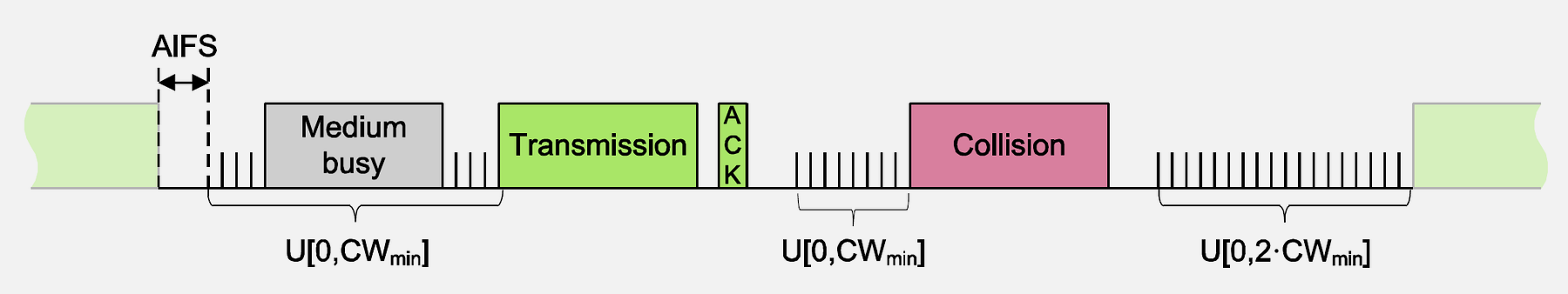
Source: CP IoT System Design Guide, Chapter 4 - Networking
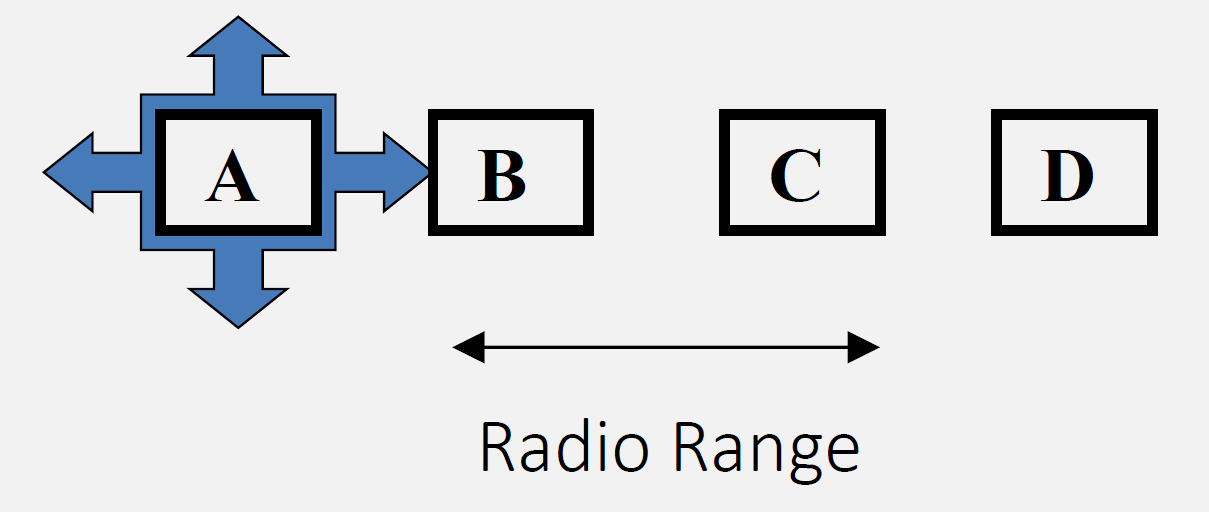
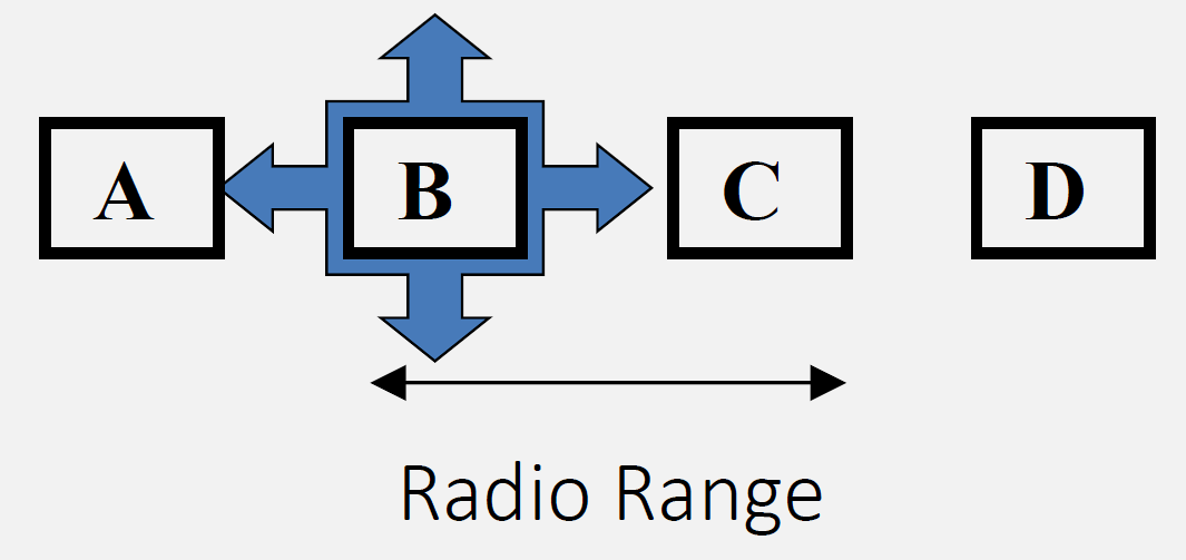
827.3.3 Exposed Terminal Problem
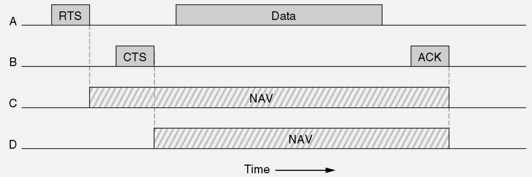
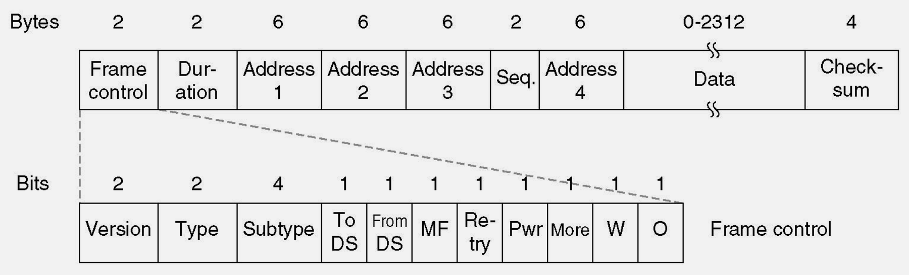
827.3.4 RTS/CTS Handshake
827.3.5 MAC Performance Characteristics
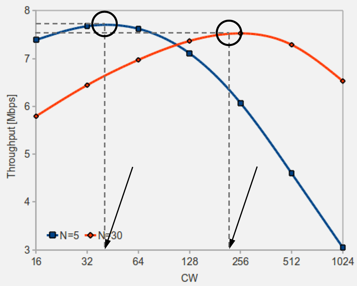
Source: CP IoT System Design Guide, Chapter 4 - Networking
827.4 Wi-Fi Architecture for IoT
827.4.1 Infrastructure Mode (Most Common)

This variant shows the same three Wi-Fi architectures from a spatial coverage perspective - emphasizing how each mode extends or limits coverage area.

Key Insight: Choose architecture based on coverage needs: Infrastructure for single room with good AP placement, Wi-Fi Direct for temporary device-to-device links, Mesh for large areas with multiple rooms or floors. Mesh eliminates dead zones through overlapping coverage.
Characteristics:
Source: CP IoT System Design Guide, Chapter 4 - Networking
- Centralized access point (AP) or router
- All devices connect to AP
- AP provides DHCP, routing, internet access
- Most common for home/office IoT
827.4.2 Wi-Fi Direct (Peer-to-Peer)

Characteristics: - Direct device-to-device connection - No router required - One device acts as soft AP - Use cases: Camera to phone, phone to printer
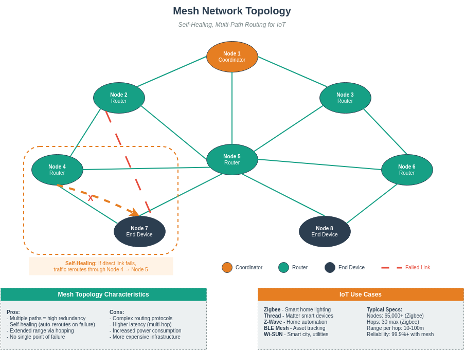
827.4.3 Wi-Fi Mesh Networks

Characteristics: - Multiple access points form a mesh - Self-healing, automatic routing - Extended coverage for large areas - Standards/implementations: IEEE 802.11s, vendor mesh systems, ESP32 frameworks (ESP-IDF ESP-Wi-Fi-MESH, Arduino painlessMesh)
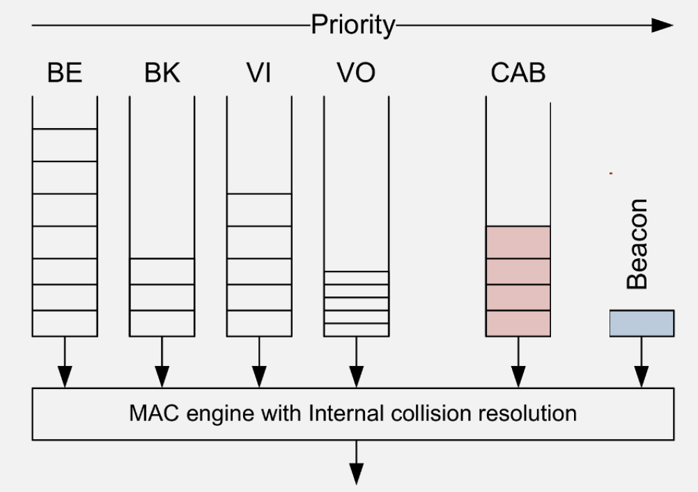
827.5 QoS and Traffic Differentiation
827.6 Videos
827.7 Real-World IoT Applications
827.7.1 Smart Home Automation

Use Case: Wi-Fi connects all smart home devices to central hub - Lights: 2.4 GHz (low bandwidth, range important) - Cameras: 5 GHz (high bandwidth video streaming) - Sensors: 2.4 GHz (battery-powered, need range)
827.7.2 Industrial IoT Monitoring
Application: Factory sensor network - Devices: 100+ sensors monitoring machines - Network: Wi-Fi 6 with OFDMA for dense deployment - Security: WPA2-Enterprise with 802.1X authentication - Topology: Mesh network for large facility coverage
827.7.3 Smart Agriculture
Application: Greenhouse monitoring - Sensors: Soil moisture, temperature, humidity (ESP32) - Power: Deep sleep mode, wake every 15 minutes - Connectivity: Wi-Fi 4 (2.4 GHz for range) - Data: MQTT over Wi-Fi to cloud platform
827.7.4 Healthcare Wearables
Application: Patient monitoring devices - Devices: Wearable sensors (heart rate, SpO2) - Connection: Wi-Fi Direct to smartphone gateway - Security: WPA3 with end-to-end encryption - Power: Wi-Fi modem sleep when idle
827.8 Visual Reference Gallery
Explore alternative visual representations of Wi-Fi mesh and network architecture concepts.


Mesh networks provide self-healing capability through redundant paths. When one node fails, traffic automatically reroutes through alternate paths, ensuring continuous connectivity.


Mesh routing protocols like AODV and HWMP discover optimal paths based on hop count, link quality, and load balancing considerations.

These templates can be customized for your specific Wi-Fi mesh deployment planning and documentation.
827.8.1 Wi-Fi Architecture Comparison
This diagram shows the key differences between Wi-Fi architecture modes:
827.8.2 Wi-Fi Architecture Selection Decision Tree
Use this flowchart to select the appropriate Wi-Fi architecture:

827.9 Summary
This chapter covered Wi-Fi MAC layer and IoT applications:
- CSMA/CA Channel Access: Carrier Sense Multiple Access with Collision Avoidance prevents simultaneous transmissions through listen-before-talk, but hidden terminals cause collisions without RTS/CTS
- RTS/CTS Handshake: Request To Send / Clear To Send mitigates hidden terminal collisions by reserving airtime (other nodes defer), improving reliability at the cost of additional overhead
- QoS Differentiation: 802.11e provides four access categories (Voice, Video, Best Effort, Background) with different AIFS and contention windows
- Smart Home: Use 2.4 GHz for range-constrained sensors, 5 GHz for bandwidth-intensive cameras
- Industrial IoT: Wi-Fi 6 with OFDMA handles dense sensor deployments; mesh extends coverage
- Agriculture: Deep sleep + periodic wake works for low-data sensors; consider LPWAN for outdoor range
- Healthcare: Wi-Fi Direct to smartphone gateway; WPA3 security essential
827.10 What’s Next
The next chapter explores Wi-Fi Design and Exercises, covering common deployment pitfalls, worked examples for roaming configuration and backhaul planning, and hands-on exercises for mesh setup and hidden terminal analysis.