%% fig-alt: "Timeline view showing data journey through network layers: starting from Application layer where user data is created, traveling down through Transport (adding port numbers), Network (adding IP addresses), Data Link (adding MAC addresses), to Physical layer (converting to signals), then across the network medium, and back up the layers on the receiving device with headers stripped at each level"
%%{init: {'theme': 'base', 'themeVariables': { 'primaryColor': '#E67E22', 'primaryTextColor': '#fff', 'primaryBorderColor': '#2C3E50', 'lineColor': '#16A085', 'secondaryColor': '#16A085', 'tertiaryColor': '#2C3E50', 'fontSize': '13px'}}}%%
sequenceDiagram
participant App as Application<br/>User Data
participant Trans as Transport<br/>+ Ports
participant Net as Network<br/>+ IP Addr
participant Link as Data Link<br/>+ MAC Addr
participant Phys as Physical<br/>Signals
participant Wire as Network Medium
participant RPhys as Physical<br/>Receive
participant RLink as Data Link<br/>Strip MAC
participant RNet as Network<br/>Strip IP
participant RTrans as Transport<br/>Strip Port
participant RApp as Application<br/>Deliver
Note over App,Phys: SENDER: Encapsulation (headers added)
App->>Trans: "Hello" + MQTT header
Trans->>Net: Segment + TCP port 1883
Net->>Link: Packet + IP 192.168.1.10
Link->>Phys: Frame + MAC aa:bb:cc:dd:ee:ff
Phys->>Wire: Radio/electrical signals
Note over Wire: Transmission across medium
Note over RPhys,RApp: RECEIVER: Decapsulation (headers removed)
Wire->>RPhys: Receive signals
RPhys->>RLink: Reconstruct frame
RLink->>RNet: Extract packet (MAC validated)
RNet->>RTrans: Extract segment (IP matched)
RTrans->>RApp: Deliver "Hello" to app
650 Encapsulation and Protocol Data Units
650.1 Learning Objectives
By the end of this chapter, you will be able to:
- Explain encapsulation: Describe how headers are added as data moves down the protocol stack
- Explain decapsulation: Describe how headers are removed as data moves up the stack
- Name Protocol Data Units (PDUs): Identify the correct PDU name at each layer (Data, Segment, Packet, Frame, Bits)
- Analyze packet overhead: Calculate the byte overhead added by protocol headers
- Trace data flow: Follow an IoT message from application to physical transmission and back
TipMVU: Minimum Viable Understanding
Core concept: Encapsulation is like putting a letter in envelopes - each layer adds its own “envelope” (header) around the data from the layer above. At the destination, each layer removes its envelope and passes the contents up.
Why it matters: Understanding encapsulation explains why small IoT messages become much larger on the wire (header overhead), why protocols like 6LoWPAN compress headers, and how to interpret packet captures in Wireshark.
Key takeaway: Data becomes Segment (Transport) becomes Packet (Network) becomes Frame (Data Link) becomes Bits (Physical). Each transformation adds addressing and control information.
650.2 Prerequisites
- OSI and TCP/IP Models: Understanding of the layered network model structure
TipFor Beginners: Encapsulation = Packaging
Just like a letter gets wrapped:
- Letter (your message) goes in an…
- Envelope (with sender/receiver address) goes in a…
- Mail bag (sorted by region) loaded on a…
- Truck/plane (physical transport)
Each layer adds its “envelope” (header) around the data from the layer above.
At the destination, each layer removes its envelope and passes the contents up.
650.3 Protocol Data Units (PDUs)
650.3.1 Data at Each Layer
As data moves through the protocol stack, it gets different names and structures at each layer.

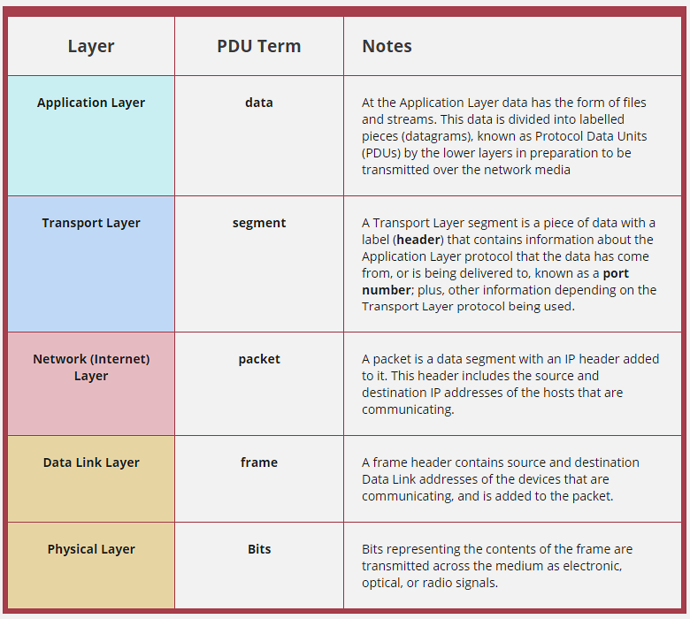
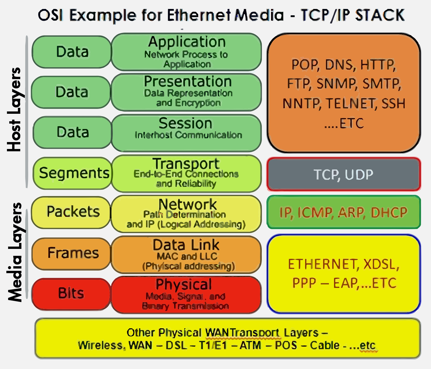
650.3.2 PDU Names by Layer
| Layer | PDU Name | Contains |
|---|---|---|
| Application | Data | Raw application data (email, file, sensor reading) |
| Transport | Segment (TCP) or Datagram (UDP) | Data + port numbers + sequence info |
| Internet | Packet | Segment + source/destination IP addresses |
| Network Access | Frame | Packet + source/destination MAC addresses |
| Physical | Bits | Electronic, radio, or optical signals |
650.4 How Data Moves Through Layers
When you send “Hello!” to a smart device:
SENDING (Your Phone)                RECEIVING (Smart Device)
━━━━━━━━━━━━━━━━━━━━━━━━━━━━━━━━━━━━━━━━━━━━━━━━━━━━━━━━━━━
APP:    "Hello!"                    APP:    "Hello!" ✓
           ↓ add MQTT header                   ↑ remove MQTT
TRANS:  [TCP][Hello!]               TRANS:  [TCP][Hello!]
           ↓ add IP header                     ↑ remove IP
NET:    [IP][TCP][Hello!]           NET:    [IP][TCP][Hello!]
           ↓ add Wi-Fi header                   ↑ remove Wi-Fi
LINK:   [Wi-Fi][IP][TCP][Hello!]     LINK:   [Wi-Fi][IP][TCP][Hello!]
           ↓                                   ↑
PHYS:   ~~~radio waves~~~    →→→    PHYS:   ~~~radio waves~~~
Key insight: Each layer adds its own “envelope” (header) going down, and removes it going up. This is called encapsulation.
650.5 IoT Example: Temperature Sensor
Your temperature sensor sends “72F” to the cloud:
| Layer | What Happens | Protocol Used |
|---|---|---|
| Application | Format: {"temp": 72} |
MQTT |
| Transport | Add sequence number, port | UDP |
| Network | Add IP addresses | 6LoWPAN (compressed IPv6) |
| Data Link | Add device addresses | Zigbee MAC |
| Physical | Convert to radio signal | 2.4 GHz radio |
Total journey: 5 layers down at sensor - over the air - 5 layers up at gateway - internet - cloud!
Application Layer Data:
{
  "sensor_id": "TEMP-001",
  "temperature": 22.5,
  "humidity": 45.0,
  "timestamp": "2025-10-25T10:30:00Z"
}
After each layer adds headers: 1. Segment: + TCP port 8883 (MQTT), sequence number 2. Packet: + IP addresses (192.168.1.100 -> 203.0.113.42) 3. Frame: + MAC addresses (sensor MAC -> gateway MAC) 4. Bits: Transmitted as Wi-Fi radio signals
650.6 Encapsulation and Decapsulation
650.6.1 The Process
Encapsulation: Headers (and trailers) are progressively ADDED as data moves DOWN the layers.
Decapsulation: Headers (and trailers) are progressively REMOVED as data moves UP the layers.


650.6.2 Email Example: The Jacket Analogy
Sending an email - data moves through layers like putting on jackets:

Think of it like: - Each layer puts a “jacket” on the data (with zippers/buttons = protocol rules) - The equivalent layer at the destination knows how to remove that jacket - Only layers at the same level understand each other’s jackets
Headers contain control and management information: - Addressing (where to send) - Sequencing (order of packets) - Error checking (data integrity) - Protocol identification (what’s inside)

650.7 Byte-Level Analysis: Understanding Overhead
650.7.1 Detailed Frame Structure
%% fig-alt: "Detailed byte-level breakdown of a network frame showing actual header sizes: Ethernet header 14 bytes (6 dest MAC + 6 src MAC + 2 type), IP header 20 bytes minimum, TCP header 20 bytes minimum, and application payload, with total overhead calculation showing that a 50-byte payload becomes 104 bytes on the wire"
%%{init: {'theme': 'base', 'themeVariables': { 'primaryColor': '#E67E22', 'primaryTextColor': '#fff', 'primaryBorderColor': '#2C3E50', 'lineColor': '#16A085', 'secondaryColor': '#16A085', 'tertiaryColor': '#2C3E50', 'fontSize': '11px'}}}%%
flowchart LR
    subgraph Frame["Complete Ethernet Frame (minimum 64 bytes)"]
        direction LR
        subgraph EthHdr["Ethernet Header: 14 bytes"]
            DestMAC["Dest MAC<br/>6 bytes"]
            SrcMAC["Src MAC<br/>6 bytes"]
            EthType["Type<br/>2 bytes"]
        end

        subgraph IPHdr["IP Header: 20 bytes min"]
            IPVer["Ver+IHL<br/>1 byte"]
            IPTOS["ToS<br/>1 byte"]
            IPLen["Length<br/>2 bytes"]
            IPId["ID<br/>2 bytes"]
            IPFlags["Flags<br/>2 bytes"]
            IPTTL["TTL<br/>1 byte"]
            IPProto["Proto<br/>1 byte"]
            IPChk["Checksum<br/>2 bytes"]
            IPSrc["Src IP<br/>4 bytes"]
            IPDst["Dst IP<br/>4 bytes"]
        end

        subgraph TCPHdr["TCP Header: 20 bytes min"]
            TCPSrc["Src Port<br/>2 bytes"]
            TCPDst["Dst Port<br/>2 bytes"]
            TCPSeq["Seq Num<br/>4 bytes"]
            TCPAck["Ack Num<br/>4 bytes"]
            TCPFlags["Flags<br/>2 bytes"]
            TCPWin["Window<br/>2 bytes"]
            TCPChk["Checksum<br/>2 bytes"]
            TCPUrg["Urgent<br/>2 bytes"]
        end

        Payload["App Data<br/>Variable"]

        FCS["FCS<br/>4 bytes"]
    end

    subgraph Summary["Overhead Analysis"]
        Calc["50-byte payload<br/>+ 14 (Eth) + 20 (IP)<br/>+ 20 (TCP) + 4 (FCS)<br/>= 108 bytes total<br/><b>54% overhead!</b>"]
    end

    style DestMAC fill:#2C3E50,stroke:#2C3E50,color:#fff
    style SrcMAC fill:#2C3E50,stroke:#2C3E50,color:#fff
    style EthType fill:#2C3E50,stroke:#2C3E50,color:#fff
    style IPVer fill:#16A085,stroke:#2C3E50,color:#fff
    style IPTOS fill:#16A085,stroke:#2C3E50,color:#fff
    style IPLen fill:#16A085,stroke:#2C3E50,color:#fff
    style IPId fill:#16A085,stroke:#2C3E50,color:#fff
    style IPFlags fill:#16A085,stroke:#2C3E50,color:#fff
    style IPTTL fill:#16A085,stroke:#2C3E50,color:#fff
    style IPProto fill:#16A085,stroke:#2C3E50,color:#fff
    style IPChk fill:#16A085,stroke:#2C3E50,color:#fff
    style IPSrc fill:#16A085,stroke:#2C3E50,color:#fff
    style IPDst fill:#16A085,stroke:#2C3E50,color:#fff
    style TCPSrc fill:#16A085,stroke:#2C3E50,color:#fff
    style TCPDst fill:#16A085,stroke:#2C3E50,color:#fff
    style TCPSeq fill:#16A085,stroke:#2C3E50,color:#fff
    style TCPAck fill:#16A085,stroke:#2C3E50,color:#fff
    style TCPFlags fill:#16A085,stroke:#2C3E50,color:#fff
    style TCPWin fill:#16A085,stroke:#2C3E50,color:#fff
    style TCPChk fill:#16A085,stroke:#2C3E50,color:#fff
    style TCPUrg fill:#16A085,stroke:#2C3E50,color:#fff
    style Payload fill:#E67E22,stroke:#2C3E50,color:#fff
    style FCS fill:#7F8C8D,stroke:#2C3E50,color:#fff
    style Calc fill:#E67E22,stroke:#2C3E50,color:#fff
650.7.2 Header Overhead Calculation
| Component | Size | Purpose |
|---|---|---|
| Ethernet Header | 14 bytes | Dest MAC (6) + Src MAC (6) + Type (2) |
| IP Header | 20 bytes min | Version, length, TTL, addresses, etc. |
| TCP Header | 20 bytes min | Ports, sequence numbers, flags, etc. |
| Frame Check Sequence | 4 bytes | Error detection |
| Total Overhead | 58 bytes | Before any payload! |
For IoT implications: - A 10-byte sensor reading becomes 68+ bytes on the wire - That’s 85% overhead for small payloads! - This is why IoT protocols like 6LoWPAN compress IPv6 headers from 40 bytes down to 2-6 bytes
650.8 Visual Reference Gallery
NoteProtocol Stack Visualizations
650.8.1 Protocol Data Units


650.9 Summary
This chapter covered how data is transformed as it moves through the protocol stack:
- Encapsulation adds headers progressively as data moves DOWN the stack (Data to Segment to Packet to Frame to Bits), with each layer wrapping the previous layer’s output
- Decapsulation removes headers progressively as data moves UP the stack, with each layer stripping its header and passing contents to the layer above
- Protocol Data Units (PDUs) have specific names: Application data becomes Transport segment/datagram, then Network packet, then Data Link frame, finally Physical bits
- Header overhead is significant: Standard TCP/IP adds 54+ bytes to every message, which is why IoT uses header compression techniques like 6LoWPAN
- Each header contains control information: addressing (where to send), sequencing (packet order), error checking (integrity), and protocol identification (what’s inside)
650.10 What’s Next
Continue your exploration of layered network models:
- IoT Reference Models: Explore IoT-specific architectures including the ITU model and Cisco 7-Level reference model
- Layered Models: Labs and Implementation: Hands-on MAC/IP addressing, ARP, and Python implementations
- Layered Models: Review: Test your understanding with comprehensive knowledge checks