%%{init: {'theme': 'base', 'themeVariables': {'primaryColor':'#E8F4F8','primaryTextColor':'#2C3E50','primaryBorderColor':'#16A085','lineColor':'#16A085','secondaryColor':'#FEF5E7','tertiaryColor':'#FDEBD0','fontSize':'14px'}}}%%
graph TB
    Packet["Incoming Packet"]

    subgraph Switch["OpenFlow Switch"]
        FlowTable["Flow Table<br/>Match-Action Rules"]
        GroupTable["Group Table<br/>Multicast/Failover"]
        Meter["Meter Table<br/>Rate Limiting"]
        SecureChannel["Secure Channel<br/>(TLS to Controller)"]
    end

    Controller["SDN Controller"]
    Output["Output Port(s)"]

    Packet -->|1. Arrives| FlowTable
    FlowTable -->|2. Match?| Decision{Match<br/>Found?}
    Decision -->|Yes| Action["Execute Actions"]
    Decision -->|No| SecureChannel

    SecureChannel -->|PACKET_IN| Controller
    Controller -->|FLOW_MOD| SecureChannel
    SecureChannel --> FlowTable

    Action --> GroupTable
    Action --> Meter
    GroupTable --> Output
    Meter --> Output

    style FlowTable fill:#16A085,stroke:#2C3E50,color:#fff
    style GroupTable fill:#2C3E50,stroke:#16A085,color:#fff
    style Meter fill:#2C3E50,stroke:#16A085,color:#fff
    style SecureChannel fill:#E67E22,stroke:#2C3E50,color:#fff
    style Controller fill:#16A085,stroke:#2C3E50,color:#fff,stroke-width:3px
    style Decision fill:#FDEBD0,stroke:#E67E22
    style Action fill:#E8F4F8,stroke:#16A085
282 SDN OpenFlow Protocol and Challenges
282.1 Learning Objectives
By the end of this chapter, you will be able to:
- Understand OpenFlow Protocol: Explain how SDN controllers communicate with network switches using OpenFlow
- Configure Flow Tables: Design and install flow table entries with match-action rules
- Analyze Flow Processing: Trace packet processing through OpenFlow switches
- Address SDN Challenges: Identify and mitigate scalability, fault tolerance, and security challenges
- Design Controller Placement: Optimize SDN controller placement for latency and reliability
282.2 Knowledge Check
Test your understanding of these architectural concepts.
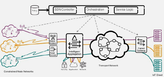
282.3 OpenFlow Protocol

OpenFlow is the standardized southbound protocol for communication between controller and switches.
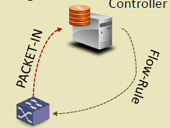
282.3.1 OpenFlow Switch Components
{fig-alt=“OpenFlow switch components showing packet processing pipeline: incoming packets match against flow table, execute actions via group/meter tables to output ports, or send PACKET_IN to controller via secure channel for new flow rules”}
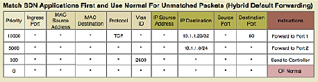
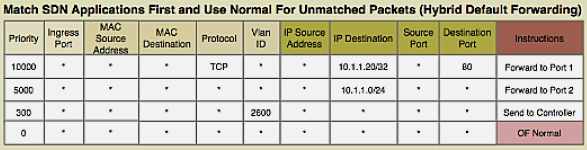
282.3.2 Flow Table Entry Structure
Each flow entry contains:
1. Match Fields (Packet Header Fields): - Layer 2: Source/Dest MAC, VLAN ID, Ethertype - Layer 3: Source/Dest IP, Protocol, ToS - Layer 4: Source/Dest Port (TCP/UDP) - Input Port - Metadata
2. Priority: - Higher priority rules matched first - Allows specific rules to override general rules
3. Counters: - Packets matched - Bytes matched - Duration
4. Instructions/Actions: - Forward to port(s) - Drop - Modify header fields (MAC, IP, VLAN) - Push/Pop VLAN/MPLS tags - Send to controller - Go to next table
5. Timeouts: - Idle Timeout: Remove rule if no matching packets for N seconds - Hard Timeout: Remove rule after N seconds regardless of activity
6. Cookie: - Opaque identifier set by controller
Example Flow Rule:
Match: src_ip=10.0.0.5, dst_ip=192.168.1.10, protocol=TCP, dst_port=80
Priority: 100
Actions: output:port3, set_vlan=100
Idle_timeout: 60
Hard_timeout: 300
282.3.3 OpenFlow Messages
282.4 SDN Challenges
282.4.1 Rule Placement Challenge
Problem: Switches have limited TCAM (Ternary Content-Addressable Memory) for storing flow rules.
TCAM Characteristics: - Fast lookup (single clock cycle) - Expensive ($15-30 per Mb) - Limited capacity (few thousand entries) - Power-hungry
Challenges: - How to select which flows to cache in TCAM? - When to evict rules (LRU, LFU, timeout-based)? - How to minimize PACKET_IN messages to controller?
Solutions: - Wildcard Rules: Match multiple flows with single rule - Hierarchical Aggregation: Aggregate at network edge - Rule Caching: Intelligent replacement algorithms - Hybrid Approaches: TCAM + DRAM for overflow
282.4.2 Controller Placement Challenge
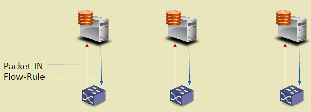


Problem: Where to place controllers for optimal performance?
Considerations: - Latency: Controller-switch delay affects flow setup time - Throughput: Controller capacity (requests/second) - Reliability: Controller failure impacts network - Scalability: Number of switches per controller
Architectures:
%%{init: {'theme': 'base', 'themeVariables': {'primaryColor':'#E8F4F8','primaryTextColor':'#2C3E50','primaryBorderColor':'#16A085','lineColor':'#16A085','secondaryColor':'#FEF5E7','tertiaryColor':'#FDEBD0','fontSize':'14px'}}}%%
graph TB
    subgraph Centralized["Centralized (Single Controller)"]
        C1["Controller"]
        S1["Switch"] & S2["Switch"] & S3["Switch"]
        C1 --> S1 & S2 & S3
    end

    subgraph Distributed["Distributed (Multiple Controllers)"]
        C2A["Controller A"] & C2B["Controller B"]
        S4["Switch"] & S5["Switch"] & S6["Switch"]
        C2A <-->|Sync| C2B
        C2A --> S4 & S5
        C2B --> S5 & S6
    end

    subgraph Hierarchical["Hierarchical (Tiered Controllers)"]
        C3Root["Root Controller"]
        C3A["Regional A"] & C3B["Regional B"]
        S7["Switch"] & S8["Switch"] & S9["Switch"] & S10["Switch"]
        C3Root --> C3A & C3B
        C3A --> S7 & S8
        C3B --> S9 & S10
    end

    style C1 fill:#16A085,stroke:#2C3E50,color:#fff
    style C2A fill:#16A085,stroke:#2C3E50,color:#fff
    style C2B fill:#16A085,stroke:#2C3E50,color:#fff
    style C3Root fill:#E67E22,stroke:#2C3E50,color:#fff
    style C3A fill:#16A085,stroke:#2C3E50,color:#fff
    style C3B fill:#16A085,stroke:#2C3E50,color:#fff
    style S1 fill:#2C3E50,stroke:#16A085,color:#fff
    style S2 fill:#2C3E50,stroke:#16A085,color:#fff
    style S3 fill:#2C3E50,stroke:#16A085,color:#fff
    style S4 fill:#2C3E50,stroke:#16A085,color:#fff
    style S5 fill:#2C3E50,stroke:#16A085,color:#fff
    style S6 fill:#2C3E50,stroke:#16A085,color:#fff
    style S7 fill:#2C3E50,stroke:#16A085,color:#fff
    style S8 fill:#2C3E50,stroke:#16A085,color:#fff
    style S9 fill:#2C3E50,stroke:#16A085,color:#fff
    style S10 fill:#2C3E50,stroke:#16A085,color:#fff
{fig-alt=“Three SDN controller placement architectures: centralized (single controller managing all switches), distributed (multiple synchronized controllers for redundancy), and hierarchical (root controller coordinating regional controllers managing switch groups)”}
Placement Strategies: - K-median: Minimize average latency to switches - K-center: Minimize maximum latency (worst-case) - Failure-aware: Ensure backup controller coverage
NoteAlternative View: Controller Failure Recovery Sequence
This variant shows what happens during a controller failure in a distributed deployment, demonstrating the failover process that maintains network operation.
%%{init: {'theme': 'base', 'themeVariables': {'primaryColor':'#2C3E50','primaryTextColor':'#fff','primaryBorderColor':'#16A085','lineColor':'#16A085','secondaryColor':'#E67E22','tertiaryColor':'#7F8C8D','fontSize':'12px'}}}%%
sequenceDiagram
    participant S as Switch
    participant P as Primary Controller
    participant B as Backup Controller
    participant DB as State Database

    Note over S,DB: Normal Operation
    S->>P: PACKET_IN (new flow)
    P->>DB: Store flow decision
    P->>S: FLOW_MOD (install rule)

    Note over P: ⚠️ Controller Fails
    P--xP: Crash / Network Partition

    Note over S,B: Failover Process (~3-5 seconds)
    S->>P: Heartbeat
    S->>S: No response (timeout 3s)
    S->>B: Connect to backup

    B->>DB: Load latest state
    DB-->>B: Network topology + flows
    B->>B: Become primary (leader election)

    B->>S: HELLO (establish connection)
    S->>B: FEATURES_REQUEST
    B-->>S: FEATURES_REPLY

    Note over S,B: Normal Operation Resumed
    S->>B: PACKET_IN (new flow)
    B->>S: FLOW_MOD (install rule)

    Note over S,DB: Existing flows continued<br/>during entire failover
NoteAlternative View: Controller Placement Trade-off Matrix
This variant presents controller architecture selection as a decision matrix, helping students choose the right approach for their IoT deployment scale.
%%{init: {'theme': 'base', 'themeVariables': {'primaryColor':'#2C3E50','primaryTextColor':'#fff','primaryBorderColor':'#16A085','lineColor':'#16A085','secondaryColor':'#E67E22','tertiaryColor':'#7F8C8D','fontSize':'14px'}}}%%
flowchart TB
    Start([Network Scale?]) --> Q1{Switches<br/>< 100?}

    Q1 -->|Yes| Centralized["CENTRALIZED<br/>───────────<br/>✅ Simple management<br/>✅ Low cost<br/>✅ Easy debugging<br/>───────────<br/>❌ Single point of failure<br/>❌ Limited scalability<br/>───────────<br/>📍 Small campus<br/>📍 Lab/prototype"]

    Q1 -->|No| Q2{Switches<br/>< 1000?}

    Q2 -->|Yes| Distributed["DISTRIBUTED<br/>───────────<br/>✅ High availability<br/>✅ Geographic spread<br/>✅ Load balancing<br/>───────────<br/>❌ Sync complexity<br/>❌ Consistency delays<br/>───────────<br/>📍 Enterprise<br/>📍 Multi-site IoT"]

    Q2 -->|No| Hierarchical["HIERARCHICAL<br/>───────────<br/>✅ Massive scale<br/>✅ Domain isolation<br/>✅ Regional autonomy<br/>───────────<br/>❌ Complex operations<br/>❌ Multiple failure domains<br/>───────────<br/>📍 Smart city<br/>📍 Carrier network"]

    style Centralized fill:#16A085,stroke:#2C3E50,color:#fff
    style Distributed fill:#E67E22,stroke:#2C3E50,color:#fff
    style Hierarchical fill:#2C3E50,stroke:#16A085,color:#fff
282.5 SDN for IoT
SDN brings significant benefits to IoT networks:
1. Intelligent Routing - Dynamic path computation based on IoT traffic patterns - Energy-aware routing for battery-powered devices - Priority-based forwarding (critical alarms vs routine telemetry)
2. Simplified Management - Centralized view of heterogeneous IoT devices - Programmatic configuration via APIs - Rapid service deployment
3. Network Slicing - Logical network per IoT application - Isolation between applications - Custom QoS per slice
4. Traffic Engineering - Real-time adaptation to congestion - Load balancing across paths - Bandwidth allocation per IoT service
5. Enhanced Security - Centralized access control - Dynamic firewall rules - Anomaly detection via flow monitoring
%%{init: {'theme': 'base', 'themeVariables': {'primaryColor':'#E8F4F8','primaryTextColor':'#2C3E50','primaryBorderColor':'#16A085','lineColor':'#16A085','secondaryColor':'#FEF5E7','tertiaryColor':'#FDEBD0','fontSize':'14px'}}}%%
graph TB
    subgraph IoTDevices["IoT Devices"]
        Temp["Temperature<br/>Sensors"]
        Camera["Security<br/>Cameras"]
        Actuator["Smart<br/>Actuators"]
    end

    subgraph FogLayer["Fog Layer"]
        Gateway["IoT Gateway"]
    end

    subgraph SDNControl["SDN Control"]
        Controller["SDN Controller<br/>• Energy-aware routing<br/>• QoS prioritization<br/>• Network slicing<br/>• Security policies"]
    end

    subgraph Network["Network Switches"]
        SW1["Switch 1"] & SW2["Switch 2"] & SW3["Switch 3"]
    end

    Cloud["Cloud Services"]

    Temp & Camera & Actuator --> Gateway
    Gateway --> SW1
    SW1 <--> SW2 <--> SW3
    SW3 --> Cloud

    Controller -->|"Flow Rules"| SW1 & SW2 & SW3
    SW1 & SW2 & SW3 -->|"Statistics"| Controller

    style Temp fill:#2C3E50,stroke:#16A085,color:#fff
    style Camera fill:#2C3E50,stroke:#16A085,color:#fff
    style Actuator fill:#2C3E50,stroke:#16A085,color:#fff
    style Gateway fill:#E67E22,stroke:#2C3E50,color:#fff
    style Controller fill:#16A085,stroke:#2C3E50,color:#fff,stroke-width:3px
    style SW1 fill:#2C3E50,stroke:#16A085,color:#fff
    style SW2 fill:#2C3E50,stroke:#16A085,color:#fff
    style SW3 fill:#2C3E50,stroke:#16A085,color:#fff
    style Cloud fill:#7F8C8D,stroke:#2C3E50,color:#fff
{fig-alt=“SDN for IoT architecture showing diverse IoT devices (temperature sensors, security cameras, smart actuators) connecting through fog gateway and SDN-managed network switches to cloud, with centralized controller providing energy-aware routing, QoS, network slicing, and security policies”}
282.6 Software-Defined WSN
Traditional WSNs are resource-constrained and vendor-specific, making dynamic reconfiguration difficult. SD-WSN applies SDN principles to wireless sensor networks.
282.6.1 Sensor OpenFlow
Concept: Adapt OpenFlow for resource-constrained sensor nodes.
Forwarding Modes: - ID-Centric: Route based on source node ID - Value-Centric: Route based on sensed value threshold - Example: Forward only if temperature > 30°C
Benefits: - Dynamic routing logic without firmware updates - Application-specific forwarding policies - Centralized network control
282.6.2 Soft-WSN
Features:
1. Sensor Management - Enable/disable sensors dynamically - Multi-sensor boards: activate subset based on application
2. Delay Management - Adjust sensing frequency in real-time - Balance freshness vs energy consumption
3. Active-Sleep Management - Dynamic duty cycling - Coordinated sleep schedules
4. Topology Management - Node-specific: Change routing at individual nodes - Network-wide: Broadcast policies (forward all, drop all)
Results: - Packet Delivery Ratio: +15-20% improvement over traditional WSN - Data Replication: -30-40% reduced redundant packets - Control Overhead: +10-15% increased due to PACKET_IN messages - Net Benefit: Overall efficiency gain despite control overhead
282.6.3 SDN-WISE
Architecture:
%%{init: {'theme': 'base', 'themeVariables': {'primaryColor':'#E8F4F8','primaryTextColor':'#2C3E50','primaryBorderColor':'#16A085','lineColor':'#16A085','secondaryColor':'#FEF5E7','tertiaryColor':'#FDEBD0','fontSize':'14px'}}}%%
graph TB
    subgraph Application["Application Layer"]
        App["Network Management<br/>Application"]
    end

    subgraph Control["Control Layer"]
        SDNWISE["SDN-WISE Controller"]
    end

    subgraph Sensor["Sensor Network"]
        Sink["Sink Node<br/>(Gateway)"]
        SN1["Sensor Node 1<br/>Flow Table"]
        SN2["Sensor Node 2<br/>Flow Table"]
        SN3["Sensor Node 3<br/>Flow Table"]
        SN4["Sensor Node 4<br/>Flow Table"]
    end

    App <-->|API| SDNWISE
    SDNWISE <-->|Control Messages| Sink
    Sink <--> SN1 & SN2
    SN1 <--> SN3
    SN2 <--> SN4
    SN3 <--> SN4

    SN1 & SN2 & SN3 & SN4 -->|"Sensor Data"| Sink

    style App fill:#E67E22,stroke:#2C3E50,color:#fff
    style SDNWISE fill:#16A085,stroke:#2C3E50,color:#fff,stroke-width:3px
    style Sink fill:#E67E22,stroke:#2C3E50,color:#fff
    style SN1 fill:#2C3E50,stroke:#16A085,color:#fff
    style SN2 fill:#2C3E50,stroke:#16A085,color:#fff
    style SN3 fill:#2C3E50,stroke:#16A085,color:#fff
    style SN4 fill:#2C3E50,stroke:#16A085,color:#fff
{fig-alt=“SDN-WISE architecture for wireless sensor networks showing application layer communicating with SDN-WISE controller, which manages sensor nodes with flow tables through sink gateway node, enabling programmable WSN routing”}
Key Features: - Flow tables adapted for sensor constraints - In-Network Packet Processing (INPP) for local computation - Programmable via any language through API - IEEE 802.15.4 compatible
282.7 What’s Next?
Now that you understand OpenFlow protocol and SDN deployment challenges, the next chapter explores:
- SDN IoT Applications: How SDN applies to wireless sensor networks, mobile networks, data centers, and anomaly detection
Related Topics: - SDN Introduction and Architecture: Return to SDN fundamentals and architecture layers - SDN Advanced Topics: Python implementations, worked examples, and common pitfalls