%%{init: {'theme': 'base', 'themeVariables': {'primaryColor': '#2C3E50', 'primaryTextColor': '#fff', 'primaryBorderColor': '#16A085', 'lineColor': '#E67E22', 'secondaryColor': '#16A085', 'tertiaryColor': '#E67E22', 'fontSize': '14px'}}}%%
graph TB
    subgraph Traditional["Traditional: Independent Lights"]
        T1[Intersection 1<br/>Pre-programmed]
        T2[Intersection 2<br/>Pre-programmed]
        T3[Intersection 3<br/>Pre-programmed]
        T4[Intersection 4<br/>Pre-programmed]
    end

    subgraph SDN["SDN: Centralized Control"]
        CTRL[Traffic Control Center<br/>Real-time Coordination]
        S1[Intersection 1<br/>Adaptive]
        S2[Intersection 2<br/>Adaptive]
        S3[Intersection 3<br/>Adaptive]
        S4[Intersection 4<br/>Adaptive]

        CTRL -->|Dynamic Timing| S1
        CTRL -->|Dynamic Timing| S2
        CTRL -->|Dynamic Timing| S3
        CTRL -->|Dynamic Timing| S4

        S1 -.->|Traffic Data| CTRL
        S2 -.->|Traffic Data| CTRL
    end

    style T1 fill:#7F8C8D,stroke:#2C3E50,color:#fff
    style T2 fill:#7F8C8D,stroke:#2C3E50,color:#fff
    style CTRL fill:#2C3E50,stroke:#16A085,color:#fff
    style S1 fill:#16A085,stroke:#2C3E50,color:#fff
    style S2 fill:#16A085,stroke:#2C3E50,color:#fff
    style S3 fill:#16A085,stroke:#2C3E50,color:#fff
    style S4 fill:#16A085,stroke:#2C3E50,color:#fff
284 SDN Core Concepts and Traditional Network Limitations
284.1 Learning Objectives
By the end of this chapter, you will be able to:
- Explain SDN Architecture: Describe the separation of control plane and data plane in software-defined networks
- Identify Traditional Network Limitations: Recognize the problems with distributed control, vendor lock-in, and static configuration
- Understand Control/Data Plane Separation: Explain how SDN moves network intelligence to a centralized controller
- Apply SDN to IoT Scenarios: Recognize why IoT networks benefit from centralized programmable control
TipMVU: Minimum Viable Understanding
Core concept: SDN separates the network’s “brain” (control plane) from its “muscles” (data plane), enabling a central controller to program how all switches forward packets instead of each device making independent decisions. Why it matters: IoT networks with thousands of diverse devices need dynamic traffic management, multi-protocol support, and rapid policy changes that traditional distributed routing cannot provide. Key takeaway: When implementing SDN, always plan for controller high availability since it becomes the single point of network intelligence - but existing traffic flows continue even if the controller fails.
284.2 Prerequisites
Before diving into this chapter, you should be familiar with:
- Networking Basics: Understanding of network protocols, routing, switching, and packet forwarding is essential for grasping how SDN transforms traditional network architecture
- IoT Reference Models: Familiarity with layered IoT architectures helps understand where SDN fits in the overall IoT system design
- Wireless Sensor Networks: Knowledge of WSN characteristics provides context for understanding SDN applications in resource-constrained IoT environments
- Cloud Computing: Understanding cloud service models (IaaS/PaaS/SaaS) draws useful parallels to SDN’s separation of control and infrastructure layers
284.3 Getting Started (For Beginners)
TipFor Kids: Meet the Sensor Squad!
SDN is like having one super-smart traffic controller for your whole city instead of having a separate person at every intersection!
284.3.1 The Sensor Squad Adventure: The Great Data Traffic Jam
Sensor City was having a big problem! Thousands of data messages were zooming around the city, but every intersection had its own traffic controller who only knew about their own corner. Messages kept crashing into each other and getting lost!
“This is chaos!” said Max the Microcontroller, watching messages pile up. Sammy the Sensor had an idea. “What if we built a tall tower in the center of town where ONE smart controller could see EVERYTHING?”
They built the SDN Tower, and Bella the Battery powered it up. From the tower, the Controller could see every street, every intersection, and every message traveling through town. When a super-important emergency message from Sammy needed to get through, the Controller said: “Clear a path on Main Street! VIP message coming through!”
All the intersections listened to the tower and immediately made way. The emergency message zoomed through without any delays! Meanwhile, regular messages took different routes that weren’t busy.
Lila the LED was amazed. “Before, every intersection did its own thing. Now, one smart controller makes the whole city work together!”
284.3.2 Key Words for Kids
| Word | What It Means |
|---|---|
| SDN (Software-Defined Networking) | Having one smart “brain” control a whole network instead of each device deciding alone |
| Controller | The smart central brain that tells all the network switches what to do |
| Data Plane | The roads where data actually travels (like streets for cars) |
| Control Plane | The decision-making part that plans where data should go (like a GPS) |
| Flow Rule | An instruction telling a switch “when you see THIS, do THAT” |
284.3.3 Try This at Home!
Build Your Own SDN City!
- Set up toy cars or LEGO figures at different spots around a room - these are your “data messages”
- Put pieces of paper at different spots - these are your “switches” (intersections)
- Stand on a chair or step stool - you’re now the SDN Controller with a view of everything!
- Have a friend be a “message” trying to get from one side of the room to the other
- YOU tell each intersection which way to point: “Paper 1: point left! Paper 2: point straight!”
- Compare this to each paper making its own random choice - which works better?
This is exactly how SDN works! Instead of every switch figuring things out alone, one smart controller sees the whole network and tells each switch exactly what to do!
TipWhat is Software-Defined Networking? (Simple Explanation)
Analogy: Think of SDN like the difference between traffic lights and a traffic control center.
Traditional Networking (Traffic Lights): - Each intersection has its own timer - No coordination between intersections - Can’t adapt to real-time traffic - To change timing, visit each light physically
SDN (Traffic Control Center): - Central controller sees all intersections - Coordinates timing across the city - Adapts to rush hour, accidents, events - Change all lights from one computer
{fig-alt=“Comparison between traditional network with independent traffic lights (4 pre-programmed intersections with no coordination) versus SDN approach with centralized traffic control center dynamically managing 4 adaptive intersections with real-time coordination and traffic data feedback”}
%%{init: {'theme': 'base', 'themeVariables': {'primaryColor': '#2C3E50', 'primaryTextColor': '#fff', 'primaryBorderColor': '#16A085', 'lineColor': '#16A085', 'secondaryColor': '#E67E22', 'tertiaryColor': '#7F8C8D'}}}%%
graph TB
    subgraph TRAD["TRADITIONAL NETWORK"]
        direction TB
        T_DEV1["Router 1<br/>Control + Data"]
        T_DEV2["Router 2<br/>Control + Data"]
        T_DEV3["Router 3<br/>Control + Data"]
        T_DEV1 ---|"Distributed<br/>Protocols"| T_DEV2
        T_DEV2 ---|"Distributed<br/>Protocols"| T_DEV3
    end

    subgraph SDN["SDN ARCHITECTURE"]
        direction TB
        subgraph APP_LAYER["Application Layer"]
            A1["Traffic Eng"]
            A2["Security"]
            A3["Load Balance"]
        end
        subgraph CTRL_LAYER["Control Layer"]
            C1["SDN Controller<br/>Global View"]
        end
        subgraph DATA_LAYER["Data Layer"]
            D1["Switch 1"]
            D2["Switch 2"]
            D3["Switch 3"]
        end

        APP_LAYER -->|"Northbound API"| CTRL_LAYER
        CTRL_LAYER -->|"OpenFlow"| DATA_LAYER
    end

    style TRAD fill:#7F8C8D,stroke:#2C3E50,stroke-width:2px
    style SDN fill:#16A085,stroke:#2C3E50,stroke-width:2px
    style APP_LAYER fill:#E67E22,stroke:#2C3E50
    style CTRL_LAYER fill:#2C3E50,stroke:#16A085
    style DATA_LAYER fill:#16A085,stroke:#2C3E50
NoteThe Two “Planes” Concept
In networking, there are two main jobs:
| Plane | What It Does | Analogy |
|---|---|---|
| Control Plane | Decides where data should go | GPS navigation deciding the route |
| Data Plane | Actually moves the data | Your car driving the route |
Traditional: Both planes in same device (router thinks AND forwards) SDN: Separated! Controller thinks, switches just forward.
%%{init: {'theme': 'base', 'themeVariables': {'primaryColor': '#2C3E50', 'primaryTextColor': '#fff', 'primaryBorderColor': '#16A085', 'lineColor': '#E67E22', 'secondaryColor': '#16A085', 'tertiaryColor': '#E67E22', 'fontSize': '14px'}}}%%
graph LR
    subgraph Traditional["Traditional Router"]
        TRAD_CTRL[Control Plane<br/>Route Decisions]
        TRAD_DATA[Data Plane<br/>Packet Forwarding]
        TRAD_CTRL --- TRAD_DATA
    end

    subgraph SDN["SDN Architecture"]
        SDN_CTRL[SDN Controller<br/>Centralized Decisions]
        SDN_SW1[Switch 1<br/>Forwarding Only]
        SDN_SW2[Switch 2<br/>Forwarding Only]
        SDN_SW3[Switch 3<br/>Forwarding Only]

        SDN_CTRL -->|Flow Rules| SDN_SW1
        SDN_CTRL -->|Flow Rules| SDN_SW2
        SDN_CTRL -->|Flow Rules| SDN_SW3
    end

    style TRAD_CTRL fill:#7F8C8D,stroke:#2C3E50,color:#fff
    style TRAD_DATA fill:#7F8C8D,stroke:#2C3E50,color:#fff
    style SDN_CTRL fill:#2C3E50,stroke:#16A085,color:#fff
    style SDN_SW1 fill:#16A085,stroke:#2C3E50,color:#fff
    style SDN_SW2 fill:#16A085,stroke:#2C3E50,color:#fff
    style SDN_SW3 fill:#16A085,stroke:#2C3E50,color:#fff
{fig-alt=“Control plane and data plane separation: traditional router with both planes tightly coupled versus SDN architecture where centralized controller (control plane) sends flow rules to three separate switches (data plane) that only perform forwarding”}
CautionWhy SDN Matters for IoT
IoT networks are dynamic and diverse—SDN helps manage this complexity:
| IoT Challenge | SDN Solution |
|---|---|
| Thousands of devices | Centralized control of all devices |
| Different protocols | Software translates between them |
| Changing requirements | Reprogram network instantly |
| Security threats | Detect and isolate attacks from center |
Real Example: Smart Factory
%%{init: {'theme': 'base', 'themeVariables': {'primaryColor': '#2C3E50', 'primaryTextColor': '#fff', 'primaryBorderColor': '#16A085', 'lineColor': '#E67E22', 'secondaryColor': '#16A085', 'tertiaryColor': '#E67E22', 'fontSize': '13px'}}}%%
graph TB
    CTRL[SDN Controller<br/>Factory Management]

    ROBOT[Robots<br/>High Priority]
    SENSORS[IoT Sensors<br/>Normal Priority]
    CAMERAS[Security Cameras<br/>Medium Priority]
    OFFICE[Office Network<br/>Low Priority]

    CTRL -->|Low Latency Path| ROBOT
    CTRL -->|Standard Path| SENSORS
    CTRL -->|Guaranteed Bandwidth| CAMERAS
    CTRL -->|Best Effort| OFFICE

    THREAT[Security Threat<br/>Detected]
    THREAT -.->|Alert| CTRL
    CTRL -.->|Isolate| SENSORS

    style CTRL fill:#2C3E50,stroke:#16A085,color:#fff
    style ROBOT fill:#E67E22,stroke:#2C3E50,color:#fff
    style SENSORS fill:#16A085,stroke:#2C3E50,color:#fff
    style THREAT fill:#E74C3C,stroke:#2C3E50,color:#fff
{fig-alt=“Smart factory SDN deployment showing controller managing four different traffic classes: robots (high priority, low latency), IoT sensors (normal priority, standard path), security cameras (medium priority, guaranteed bandwidth), office network (low priority, best effort), plus security threat detection triggering sensor isolation”}
TipSelf-Check Questions
Before diving deeper, test your understanding:
- What’s the main difference between traditional networking and SDN?
- Hint: Where is the “brain” located?
- What does “control plane” mean?
- Hint: Think GPS navigation vs driving
- Why is SDN useful for IoT networks with thousands of devices?
- Hint: How would you update 1000 routers manually?
Answers explored in the sections below!
284.4 Key Concepts
- Software-Defined Networking (SDN): Network architecture decoupling control plane (decision-making) from data plane (packet forwarding) for centralized programmable control
- Control Plane: Centralized intelligence determining how network traffic should be routed and managed across the network
- Data Plane: Distributed forwarding infrastructure executing packet transmission decisions made by the control plane
- OpenFlow: Protocol enabling SDN controllers to communicate with network switches, instructing them how to forward packets
- Network Programmability: Ability to dynamically modify network behavior through software without reconfiguring hardware devices
- SDN Controller: Centralized software application managing network-wide policies and configuring individual network devices
NoteKey Takeaway
In one sentence: SDN separates the network’s “brain” (control plane) from its “muscles” (data plane), enabling centralized programmable control over diverse IoT devices instead of configuring each switch independently.
Remember this rule: When your IoT network needs dynamic traffic management, multi-protocol support, or network-wide policy changes in seconds rather than hours, SDN provides the architectural foundation - but always plan for controller high availability since it becomes a critical control point.
284.5 Introduction
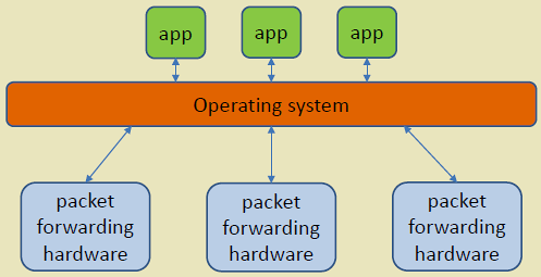
Software-Defined Networking (SDN) revolutionizes network architecture by decoupling the control plane (decision-making) from the data plane (packet forwarding). This separation enables centralized, programmable network management—particularly valuable for IoT where diverse devices, dynamic topologies, and application-specific requirements demand flexible networking.
This chapter introduces SDN core concepts and examines the limitations of traditional networks that SDN addresses.
%%{init: {'theme': 'base', 'themeVariables': {'primaryColor': '#2C3E50', 'primaryTextColor': '#fff', 'primaryBorderColor': '#16A085', 'lineColor': '#E67E22', 'secondaryColor': '#16A085', 'tertiaryColor': '#E67E22', 'fontSize': '14px'}}}%%
graph TB
    APP[SDN Applications<br/>Traffic Engineering, Security, Load Balancing]
    CTRL[SDN Controller<br/>Centralized Intelligence]
    SW1[Switch 1]
    SW2[Switch 2]
    SW3[Switch 3]
    IOT1[IoT Device 1]
    IOT2[IoT Device 2]
    IOT3[IoT Device 3]

    APP -->|Northbound API| CTRL
    CTRL -->|OpenFlow| SW1
    CTRL -->|OpenFlow| SW2
    CTRL -->|OpenFlow| SW3

    IOT1 --> SW1
    IOT2 --> SW2
    IOT3 --> SW3

    style APP fill:#E67E22,stroke:#2C3E50,color:#fff
    style CTRL fill:#2C3E50,stroke:#16A085,color:#fff
    style SW1 fill:#16A085,stroke:#2C3E50,color:#fff
    style SW2 fill:#16A085,stroke:#2C3E50,color:#fff
    style SW3 fill:#16A085,stroke:#2C3E50,color:#fff
{fig-alt=“SDN architecture overview showing application layer (traffic engineering, security, load balancing) connecting to centralized controller via northbound API, controller managing three OpenFlow switches via southbound API, and three IoT devices connected to respective switches”}
%% fig-alt: "SDN packet handling lifecycle showing what happens when an IoT device sends a new packet: Switch receives packet with no matching flow rule, switch sends packet-in to controller, controller decides action based on policy, controller installs flow rule in switch, switch forwards packet using new rule, subsequent packets from same flow are handled locally without controller"
%%{init: {'theme': 'base', 'themeVariables': {'primaryColor': '#2C3E50', 'primaryTextColor': '#fff', 'primaryBorderColor': '#16A085', 'lineColor': '#16A085', 'secondaryColor': '#E67E22', 'tertiaryColor': '#7F8C8D', 'fontSize': '12px'}}}%%
sequenceDiagram
    participant IOT as IoT Device
    participant SW as OpenFlow Switch
    participant CTRL as SDN Controller
    participant APP as Security App

    Note over IOT,APP: FIRST PACKET - No Flow Rule Exists

    rect rgb(44, 62, 80)
    IOT->>SW: Packet arrives
    Note over SW: No matching rule<br/>in flow table
    SW->>CTRL: PACKET_IN:<br/>"What do I do with this?"
    end

    rect rgb(22, 160, 133)
    CTRL->>APP: Query policy
    APP->>CTRL: "Allow this IoT device"
    CTRL->>SW: FLOW_MOD:<br/>"Install rule: Forward to port 2"
    Note over SW: Flow table updated
    end

    rect rgb(230, 126, 34)
    SW->>IOT: Forward packet<br/>(via port 2)
    Note over SW: Rule installed:<br/>Match: src=IoT1<br/>Action: output port 2
    end

    Note over IOT,APP: SUBSEQUENT PACKETS - Flow Rule Exists

    rect rgb(127, 140, 141)
    IOT->>SW: More packets arrive
    Note over SW: Match found!<br/>No controller needed
    SW->>IOT: Forward locally<br/>(microseconds)
    end

    Note over IOT,APP: KEY INSIGHT: Controller only involved<br/>for first packet of each flow
284.6 Limitations of Traditional Networks
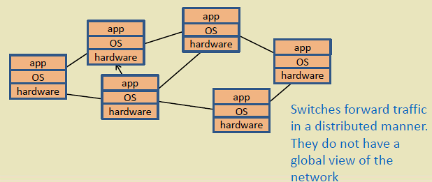
Traditional networks distribute intelligence across switches/routers, leading to several challenges:
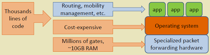
1. Vendor Lock-In - Proprietary switch OS and interfaces - Limited interoperability between vendors - Difficult to introduce new features
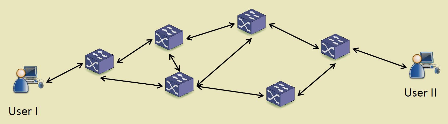
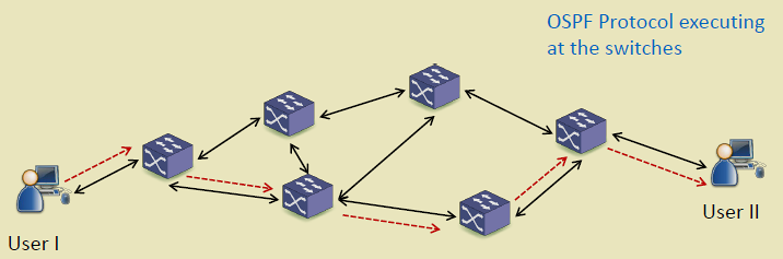
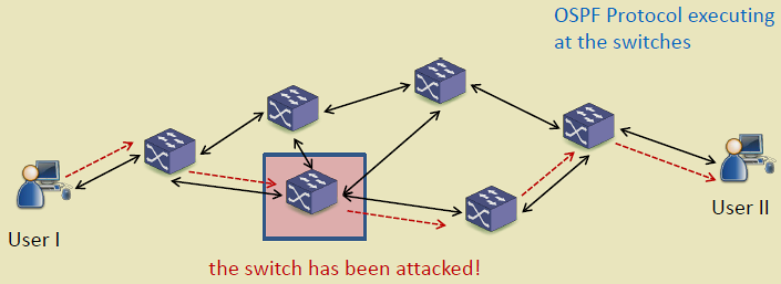
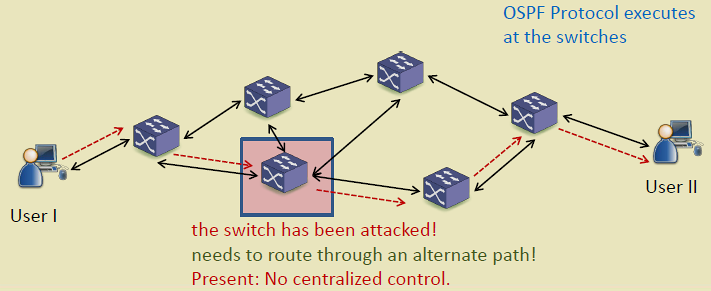
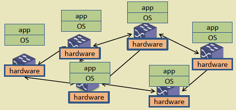
2. Distributed Control - Each switch runs independent routing protocols (OSPF, BGP) - No global network view - Suboptimal routing decisions - Difficult coordination for traffic engineering
3. Static Configuration - Manual configuration per device - Slow deployment of network changes - High operational complexity - Prone to misconfiguration
4. Inflexibility - Cannot dynamically adapt to application needs - Fixed QoS policies - Limited support for network slicing
%%{init: {'theme': 'base', 'themeVariables': {'primaryColor': '#2C3E50', 'primaryTextColor': '#fff', 'primaryBorderColor': '#16A085', 'lineColor': '#E67E22', 'secondaryColor': '#16A085', 'tertiaryColor': '#E67E22', 'clusterBkg': '#f9f9f9', 'clusterBorder': '#2C3E50', 'fontSize': '13px'}}}%%
graph TB
    subgraph Traditional["Traditional Network Limitations"]
        L1[Vendor Lock-In<br/>Proprietary Systems]
        L2[Distributed Control<br/>No Global View]
        L3[Manual Configuration<br/>Slow Deployment]
        L4[Inflexible<br/>Static Policies]
    end

    subgraph Problems["Resulting Problems"]
        P1[High OPEX]
        P2[Suboptimal Routing]
        P3[Slow Adaptation]
        P4[Limited Innovation]
    end

    L1 --> P1
    L2 --> P2
    L3 --> P3
    L4 --> P4

    style L1 fill:#E74C3C,stroke:#2C3E50,color:#fff
    style L2 fill:#E74C3C,stroke:#2C3E50,color:#fff
    style L3 fill:#E74C3C,stroke:#2C3E50,color:#fff
    style L4 fill:#E74C3C,stroke:#2C3E50,color:#fff
    style P1 fill:#7F8C8D,stroke:#2C3E50,color:#fff
    style P2 fill:#7F8C8D,stroke:#2C3E50,color:#fff
    style P3 fill:#7F8C8D,stroke:#2C3E50,color:#fff
    style P4 fill:#7F8C8D,stroke:#2C3E50,color:#fff
{fig-alt=“Traditional network limitations flowchart showing four main problems (vendor lock-in with proprietary systems, distributed control with no global view, manual configuration causing slow deployment, inflexible static policies) leading to four resulting problems (high OPEX, suboptimal routing, slow adaptation, limited innovation)”}
284.7 Summary
This chapter introduced the core concepts of Software-Defined Networking:
- Control and Data Plane Separation: SDN decouples the control plane (centralized decision-making) from the data plane (distributed packet forwarding), enabling programmable network management
- Traditional Network Limitations: Vendor lock-in, distributed control without global view, manual configuration, and static policies create operational challenges
- SDN Value for IoT: Centralized control enables dynamic traffic management, multi-protocol support, and rapid reconfiguration essential for diverse IoT deployments
- Key Terminology: Control plane (decision-making), data plane (forwarding), flow rules (match-action instructions), controller (central network intelligence)
284.8 What’s Next
The next chapter examines SDN Architecture in detail, exploring the three-layer model (application, control, infrastructure), controller design, and the tradeoffs between centralized and distributed SDN controllers.