%%{init: {'theme': 'base', 'themeVariables': { 'primaryColor': '#2C3E50', 'primaryTextColor': '#fff', 'primaryBorderColor': '#16A085', 'lineColor': '#16A085', 'secondaryColor': '#E67E22'}}}%%
graph TB
    M["Master"]
    S1["Slave 1"]
    S2["Slave 2"]

    M -->|"MOSI (Master Out)"| S1
    S1 -->|"MISO (Slave Out)"| M
    M -->|"SCK (Clock)"| S1
    M -->|"SS1 (Chip Select)"| S1

    M -->|"MOSI (Shared)"| S2
    S2 -->|"MISO (Shared)"| M
    M -->|"SCK (Shared)"| S2
    M -->|"SS2 (Dedicated)"| S2

    style M fill:#2C3E50,stroke:#16A085,color:#fff
    style S1 fill:#16A085,stroke:#16A085,color:#fff
    style S2 fill:#16A085,stroke:#16A085,color:#fff
795 SPI: Serial Peripheral Interface Protocol
795.1 Learning Objectives
By the end of this section, you will be able to:
- Understand SPI Architecture: Explain the four-wire structure with MOSI, MISO, SCK, and SS
- Configure SPI Modes: Select appropriate clock polarity (CPOL) and phase (CPHA)
- Wire SPI Devices: Connect multiple slaves using chip select lines
- Compare Protocols: Choose between SPI, I2C, and UART for specific applications
- Debug SPI Issues: Troubleshoot mode mismatch, chip select problems, and signal integrity
- Write SPI Code: Program Arduino/ESP32 to communicate with SD cards and displays
795.2 Prerequisites
Before diving into this chapter, you should be familiar with:
- Wired Communication Fundamentals: Understanding of synchronous communication, full-duplex, multi-point topology
- I2C Protocol: Comparison with I2C helps understand when to choose SPI
795.3 SPI Overview
SPI (Serial Peripheral Interface) is a high-speed, full-duplex synchronous protocol developed by Motorola.
No official standard - implementations vary slightly between manufacturers.
795.3.1 Characteristics
| Feature | Value |
|---|---|
| Wires | 4+ wires (SCLK, MOSI, MISO, + 1 SS per slave) |
| Topology | Multi-point (star) |
| Sync/Async | Synchronous (SCLK = clock) |
| Duplex | Full-duplex (simultaneous send/receive) |
| Speed | Up to 10+ Mbps (much faster than I2C) |
| Distance | <1 meter (short cables, same PCB) |
| Devices | Unlimited (limited by SS pins available) |
| Master/Slave | Single master, multiple slaves |
795.4 SPI Signals
Signal names (vary by manufacturer):
| Function | Alternative Names |
|---|---|
| SCLK | SCK, CLK (Serial Clock) |
| MOSI | SDI, DI, SI (Master Out Slave In) |
| MISO | SDO, DO, SO (Master In Slave Out) |
| SS | CS, CE (Slave Select / Chip Select) |
SCLK (Serial Clock):
- Clock signal from master
- Slaves synchronize to this clock
MOSI (Master Out, Slave In):
- Data from master to slave
- Master writes, slaves read
MISO (Master In, Slave Out):
- Data from slaves to master
- Slaves write, master reads
SS (Slave Select):
- Active LOW (usually)
- Master pulls LOW to select specific slave
- Separate SS line for each slave
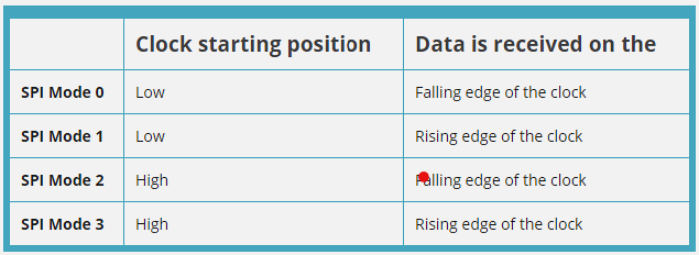
795.5 SPI Modes
SPI has 4 modes based on clock polarity (CPOL) and phase (CPHA):
| Mode | CPOL | CPHA | Clock Idle | Data Sampled |
|---|---|---|---|---|
| 0 | 0 | 0 | LOW | Rising edge |
| 1 | 0 | 1 | LOW | Falling edge |
| 2 | 1 | 0 | HIGH | Falling edge |
| 3 | 1 | 1 | HIGH | Rising edge |
CPOL (Clock Polarity):
- 0 = Clock idle state is LOW
- 1 = Clock idle state is HIGH
CPHA (Clock Phase):
- 0 = Data sampled on leading edge (first transition)
- 1 = Data sampled on trailing edge (second transition)
Most common: Mode 0 and Mode 3
Important: Master and slave must use same mode!
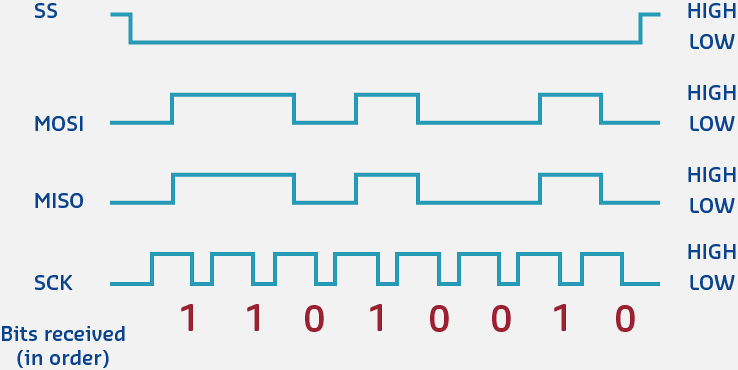
795.6 SPI Data Transfer
Full-duplex simultaneous transfer:
     SS   ____                        ________
              \______________________/

   SCLK   ___   _   _   _   _   _   ___
             \_/ \_/ \_/ \_/ \_/ \_/

   MOSI   ====X===X===X===X===X===X=====
          (Master sends data to slave)

   MISO   ====X===X===X===X===X===X=====
          (Slave sends data to master)

          Bit: 7   6   5   4   3   2   1   0
Process:
- Master pulls SS LOW (select slave)
- Master generates clock pulses on SCLK
- On each clock pulse:
- Master outputs bit on MOSI
- Slave outputs bit on MISO
- Both sides shift data simultaneously
- After 8 (or 16) bits, transaction complete
- Master pulls SS HIGH (deselect slave)
Data transmitted MSB first (most significant bit first) - can be configured.
795.7 Arduino/ESP32 SPI Example
#include <SPI.h>

// SS (Chip Select) pin
#define SS_PIN 5

void setup() {
  Serial.begin(115200);

  // Initialize SPI
  SPI.begin();

  // Configure SS pin
  pinMode(SS_PIN, OUTPUT);
  digitalWrite(SS_PIN, HIGH);  // Deselect

  Serial.println("SPI Initialized");
}

void loop() {
  // Select slave
  digitalWrite(SS_PIN, LOW);

  // Transfer data (sends 0xAA, receives slave's response)
  SPI.beginTransaction(SPISettings(1000000, MSBFIRST, SPI_MODE0));
  byte response = SPI.transfer(0xAA);
  SPI.endTransaction();

  // Deselect slave
  digitalWrite(SS_PIN, HIGH);

  Serial.print("Sent: 0xAA, Received: 0x");
  Serial.println(response, HEX);

  delay(1000);
}
Wiring (ESP32 default SPI pins):
ESP32 GPIO 18 (SCLK) -> Slave SCLK
ESP32 GPIO 23 (MOSI) -> Slave MOSI
ESP32 GPIO 19 (MISO) -> Slave MISO
ESP32 GPIO 5  (SS)   -> Slave SS/CS
ESP32 GND            -> Slave GND
Common SPI devices:
- SD card modules
- TFT/OLED displays
- NRF24L01 radio modules
- ADXL345 accelerometer
- MCP3008 ADC
TipPractical Tips
Choosing the Right SPI Mode:
- Check device datasheet - Look for CPOL/CPHA or explicit mode number
- Try Mode 0 first - Works with ~80% of SPI devices
- Try Mode 3 second - If Mode 0 fails (some displays, Ethernet)
- Modes 1 and 2 rare - Only specific industrial/legacy devices
Common Mode Assignments:
- SD Cards: Mode 0 (CPOL=0, CPHA=0)
- TFT Displays: Mode 0 or Mode 3
- ADXL345: Mode 3 (CPOL=1, CPHA=1)
- NRF24L01: Mode 0
- W5500 Ethernet: Mode 0
Debugging Mode Issues:
- Symptom: Garbled data, bits shifted
- Solution: Try different modes (SPI_MODE0 through SPI_MODE3)
- Test: Send known byte (0xAA = 10101010), verify response
795.8 Hands-On Lab: SD Card Reader
Objective: Read/write files to SD card via SPI.
#include <SPI.h>
#include <SD.h>

#define SD_CS 5  // Chip Select pin

void setup() {
  Serial.begin(115200);

  if (!SD.begin(SD_CS)) {
    Serial.println("SD card initialization failed!");
    return;
  }
  Serial.println("SD card initialized");

  // Write to file
  File file = SD.open("/test.txt", FILE_WRITE);
  if (file) {
    file.println("Hello from ESP32!");
    file.close();
    Serial.println("File written");
  }

  // Read from file
  file = SD.open("/test.txt");
  if (file) {
    Serial.println("\nFile contents:");
    while (file.available()) {
      Serial.write(file.read());
    }
    file.close();
  }
}

void loop() {}
795.9 Knowledge Check: SPI Signal Integrity
TipUnderstanding Check: SPI Signal Integrity at High Speeds
Scenario: Your data logger uses an SPI flash memory (Winbond W25Q128) rated for 133 MHz clock. Tests at 80 MHz work reliably (98% success rate), but at 133 MHz you see 40% corruption. A logic analyzer reveals clock signal overshoot (+5.8V on 3.3V logic) and ringing (+/-0.8V oscillations lasting 12 ns).
Think about:
- Why do PCB traces behave differently at 133 MHz vs 10 MHz?
- What physical phenomena cause the overshoot and ringing?
Key Insight: At high frequencies, transmission line effects dominate PCB design. A 10 cm trace at 133 MHz becomes an antenna:
- Signal wavelength: lambda = c/f = (3x10^8 m/s) / (133x10^6 Hz) = 2.26 meters
- Critical length: lambda/10 = 22.6 cm (your trace is 10 cm -> significant effects)
- Fast edge time: ~2 ns (10%-90% rise) creates harmonics up to 500 MHz
Root causes:
- Impedance mismatch: 50 ohm PCB trace -> 10 ohm chip pin creates reflection coefficient Gamma = (10-50)/(10+50) = -0.67 (67% negative reflection)
- Reflected wave: Bounces back toward source, interfering with forward signal (ringing)
- Overshoot: Reflected wave adds to forward wave (constructive interference)
Solutions:
- Series termination: 22-33 ohm resistor at source dampens reflections
- Shorter traces: Reduce to <5 cm (<lambda/40 at 133 MHz)
- Controlled impedance: Design 50 ohm traces (width/height ratio)
- Ground plane: Continuous plane under signal reduces loop inductance
Verify Your Understanding:
- Why does this matter more at 133 MHz than 10 MHz? Because lambda/10 at 10 MHz = 3 meters (trace is insignificant). At 133 MHz, lambda/10 = 22 cm (trace is significant fraction).
- Calculate required series resistor: Source impedance (5 ohm) + resistor (27 ohm) = 32 ohm approximately equal to 50 ohm trace impedance (minimizes reflections).
795.10 Protocol Comparison for IoT
795.10.1 When to Use Each Protocol
| Protocol | Best For | Avoid When |
|---|---|---|
| RS-232 | GPS modules, serial debugging, industrial legacy systems | Multiple devices on same bus, high speed needed |
| I2C | Multiple low-speed sensors (temp, humidity, pressure), displays, EEPROMs | High-speed data transfer (video, audio), long cables |
| SPI | High-speed sensors, SD cards, displays, radio modules | Pin count is limited, long-distance communication |
795.10.2 Detailed Comparison
%%{init: {'theme': 'base', 'themeVariables': { 'primaryColor': '#2C3E50', 'primaryTextColor': '#fff', 'primaryBorderColor': '#16A085', 'lineColor': '#16A085', 'secondaryColor': '#E67E22'}}}%%
graph TD
    Start["Choose Protocol"]

    Start --> Q1{"How many<br/>devices?"}
    Q1 -->|"2 only"| UART["UART/RS-232<br/>2 wires<br/>115 kbps<br/>Point-to-point"]
    Q1 -->|"3+"| Q2{"Speed<br/>requirement?"}

    Q2 -->|"< 400 kbps"| I2C["I2C<br/>2 wires<br/>400 kbps<br/>Up to 112 devices<br/>Addressable"]
    Q2 -->|"> 1 Mbps"| SPI["SPI<br/>4+ wires<br/>10+ Mbps<br/>Full-duplex<br/>Fast"]

    style Start fill:#2C3E50,stroke:#16A085,color:#fff
    style Q1 fill:#7F8C8D,stroke:#16A085,color:#fff
    style Q2 fill:#7F8C8D,stroke:#16A085,color:#fff
    style UART fill:#E67E22,stroke:#16A085,color:#fff
    style I2C fill:#16A085,stroke:#16A085,color:#fff
    style SPI fill:#2C3E50,stroke:#16A085,color:#fff
795.10.3 Practical Trade-offs
I2C Advantages:
- Only 2 wires (minimal pins)
- Easy to add devices (just connect to bus)
- Addressable (up to 112 devices)
- Bidirectional on same wire
I2C Disadvantages:
- Slower than SPI
- Pull-up resistors required
- Address conflicts possible
- Limited cable length
SPI Advantages:
- Very fast (10+ Mbps)
- Full-duplex (simultaneous send/receive)
- Simple, no addressing
- No pull-up resistors needed
SPI Disadvantages:
- More wires (4+ pins)
- Separate SS for each slave (pin intensive)
- No multi-master capability
- No flow control
TipProtocol Selection Guide
Choose UART when:
- Point-to-point communication (2 devices)
- Serial debugging or console needed
- GPS module, Bluetooth HC-05/HC-06
- Cable lengths up to 15 meters
Choose I2C when:
- Multiple devices (2-112 on same bus)
- Limited pins (only 2 wires available: SDA, SCL)
- Low-to-medium speed OK (< 400 kHz)
- Sensors, displays, EEPROMs, RTCs
Choose SPI when:
- High speed required (1-10+ Mbps)
- Enough pins available (4+ wires)
- SD cards, TFT displays, fast sensors
- Full-duplex needed (simultaneous TX/RX)
Real-World Examples:
- Weather station: I2C (BME280, OLED display on same bus)
- Data logger: SPI (SD card for fast writes)
- GPS tracker: UART (GPS module + serial debug)
- Robot: Mixed (I2C for sensors, SPI for displays, UART for debug)
795.11 Quiz: SPI and Protocol Comparison
795.12 Summary
This chapter covered SPI (Serial Peripheral Interface) protocol and protocol comparison:
- Four-wire interface (SCLK, MOSI, MISO, SS) enables high-speed full-duplex communication
- SPI modes (0-3) define clock polarity and phase - must match between master and slave
- Chip select (SS/CS) lines enable multi-slave configurations with separate select per device
- Speed advantage: 10+ Mbps vs I2C’s 400 kbps, ideal for SD cards, displays, and fast sensors
- Trade-off: More pins (4+ wires) vs I2C’s 2 wires, no multi-master, no addressing
- Protocol selection: UART for point-to-point, I2C for multi-device low-speed, SPI for high-speed
795.13 What’s Next
Having mastered wired protocols, explore complementary topics:
- Wireless Communication: Wi-Fi, Bluetooth, Zigbee, and LoRaWAN for cable-free IoT connectivity
- Industrial Networking: Deep dive into Modbus RTU/TCP, CANopen, EtherCAT, and PROFINET
- Network Protocols: TCP/IP, MQTT, CoAP, and HTTP for application-layer communication
- Sensor Interfacing: Practical projects connecting temperature, humidity, accelerometer, and display modules
- Protocol Analyzers: Using logic analyzers and bus sniffers to debug communication issues
- Wired Communication Overview: Return to the overview page