1045 UWB Applications and Security
1045.1 Learning Objectives
By the end of this chapter, you will be able to:
- Evaluate UWB applications across automotive, industrial, healthcare, and consumer domains
- Understand UWB security features including IEEE 802.15.4z secure ranging
- Explain how UWB prevents relay attacks in access control systems
- Implement UWB ranging concepts through hands-on simulation
- Identify common pitfalls in UWB deployments and their mitigations
1045.2 Introduction
UWB’s unique combination of precision, security, and low latency enables applications impossible with other technologies. This chapter explores real-world applications and the security features that make UWB ideal for access control and secure ranging.
1045.3 Applications and Use Cases
1045.3.1 Automotive Digital Keys and Access Control
Use Case: Secure, hands-free vehicle access
How It Works: 1. Car has 6-8 UWB anchors (4 doors, trunk, inside cabin) 2. Phone/key fob has UWB tag 3. Continuous ranging determines precise distance and direction 4. Car unlocks only when authorized device is within 1-2 meters of specific door 5. Secure ranging prevents relay attacks
Deployed Systems: - BMW: UWB digital keys (2020+) - Audi: UWB integration (2021+) - Tesla: UWB support announced - Volkswagen, Mercedes: In development
Security Advantage: Traditional keyless entry vulnerable to relay attacks (amplify signal from inside house to car). UWB’s time-of-flight measurement makes relay attacks detectable (speed of light limits).
1045.3.2 Asset Tracking and Logistics
Warehouse Tracking:
Scenario: 50,000 m² distribution center, 500 forklifts and 10,000 pallets
- Anchors: 125-200 UWB anchors (400 m² per anchor)
- Tags: Active tags on forklifts, passive tags on high-value pallets
- Method: TDoA for scalability
- Accuracy: 30 cm (know which aisle, which shelf position)
- Update rate: 1-10 Hz
- Benefits:
- Real-time inventory location
- Optimize pick routes (reduce travel by 20-30%)
- Safety: Prevent forklift-pedestrian collisions
- Dwell time analytics
Cost Model: - Anchors: $200-400 each × 150 = $30-60k - Active tags: $50-100 each × 500 = $25-50k - Passive tags: $10-20 each × 10,000 = $100-200k - Infrastructure (gateway, server): $20-50k - Total: $175-360k for 50,000 m² - ROI: Typically 12-18 months from efficiency gains
1045.3.3 Smart Home and IoT Devices
Apple’s Directional AirDrop and Handoff:
- iPhone/HomePod use UWB to detect which device you’re pointing at
- Point iPhone at HomePod: Transfer music playback
- Point at another iPhone: Prioritize for AirDrop
- Accuracy: ~10 cm and angular direction
Future Smart Home Applications: - Device Control: Point at smart light to adjust brightness - Contextual Automation: TV turns on when you sit on couch (not just enter room) - Multi-User: Different settings for each family member based on position - Security: Unlock only when specific person approaches specific door
1045.3.4 Industrial Safety and Geofencing
Hazardous Zone Protection:
Scenario: Chemical plant with restricted areas
- Tags: Workers wear UWB badges
- Zones: Geofences around hazardous equipment
- Precision: 30 cm accuracy prevents false alarms
- Alerts: Real-time warnings if unauthorized entry
- Evacuation: Know exact worker locations in emergency
Construction Site Safety: - Track worker proximity to heavy machinery - Automatic equipment shutdown if worker too close - Regulatory compliance (OSHA)
1045.3.5 Healthcare and Patient Monitoring
Hospital Asset and Patient Tracking:
- Equipment: IV pumps, wheelchairs, ventilators (prevent loss, optimize utilization)
- Patients: Wandering prevention (dementia care), infant security
- Staff: Optimize workflows, emergency response
- Accuracy Needs: Room-level (3-5m) often sufficient, UWB provides margin
Advantages over BLE: - Higher accuracy: Know specific bed, not just room - Better reliability: Less interference in RF-noisy hospital environment - Faster updates: Real-time tracking for patient safety
1045.4 Security Features
UWB’s physical layer properties provide inherent security advantages, enhanced in recent standards.
1045.4.1 Secure Ranging (IEEE 802.15.4z)
Scrambled Timestamp Sequence (STS):
The 802.15.4z standard introduced STS to prevent relay and spoofing attacks:
- Shared Secret: Devices establish cryptographic key
- Timestamp Scrambling: Scramble timestamp bits with AES-128
- Verification: Receiver checks scrambled sequence matches expected
- Attack Prevention: Attacker can’t replay or modify without key
Relay Attack Protection:
Traditional ranging vulnerable to relay attack: - Attacker captures signal at car - Relays to accomplice near key inside house - Car unlocked (thinks key is nearby)
UWB prevents this: - Relay introduces time delay (even nanoseconds) - Time-of-flight calculation detects extra delay - Distance computed is greater than actual - System rejects ranging result
Physical Layer Security:
- Wide bandwidth makes jamming difficult (spread across GHz)
- Short pulses difficult to intercept and decode
- Low power density (appears as noise floor)
- Covert communication possible
1045.4.2 Privacy Considerations
Location Privacy:
UWB enables precise tracking, raising privacy concerns:
- Data minimization: Only collect positioning data when necessary
- Anonymization: Separate tag ID from user identity when possible
- Consent: Clear opt-in for tracking
- Access control: Strict controls on who can access location data
- Retention: Limit storage duration
Regulatory Compliance: - GDPR (Europe): Location is personal data - CCPA (California): Location tracking disclosure requirements - Industry standards: ISO/IEC 29003 for location privacy
1045.5 Understanding Check
You’ve been asked to design a UWB positioning system for a warehouse with the following requirements:
Warehouse Specifications: - Dimensions: 200m × 250m = 50,000 m² - Height: 12m (high-bay warehouse) - Tracking targets: 500 forklifts, 200 high-value carts - Required accuracy: 50 cm - Update rate: Minimum 5 Hz (real-time) - Obstacles: Metal shelving racks, pallets, inventory
Questions:
How many UWB anchors do you need? Justify your calculation.
TWR or TDoA - which would you choose and why?
What’s your infrastructure cost estimate? (Use $300/anchor, $75/active tag, $25/passive tag)
Where would you place the anchors? Consider height and distribution.
What challenges do you anticipate with metal shelving? How would you mitigate?
Detailed Solution:
1. Anchor Count Calculation:
For a warehouse with significant obstacles, use ~300 m² per anchor (more conservative than open office): - Total area: 50,000 m² - Anchors needed: 50,000 / 300 = 167 anchors (minimum) - Add 20% redundancy for coverage gaps: 167 × 1.2 = 200 anchors
Alternative calculation by spacing: - Typical anchor spacing for warehouses: 15-20m - Grid: 200m / 15m = 14 rows, 250m / 15m = 17 columns - Total: 14 × 17 = 238 anchors - Recommendation: 200-240 anchors
2. TWR vs TDoA Decision:
Choose TDoA for the following reasons:
| Factor | TWR | TDoA | Winner |
|---|---|---|---|
| Number of tags | 700 total | 700 total | TDoA (scales better) |
| Tag power | High (active ranging) | Low (blink only) | TDoA |
| Infrastructure | Simpler | Requires sync | TWR |
| Update rate | Limited by exchanges | High (100+ Hz possible) | TDoA |
| Cost per tag | $75 (active) | $25 (passive) | TDoA |
With 700 tags and 5+ Hz requirement, TDoA is clearly superior. Tag cost savings alone: (700 × $50 savings) = $35,000.
3. Infrastructure Cost Estimate:
Anchors: 200 × $300 = $60,000
Tags: - 500 active forklift tags @ $75 = $37,500 - 200 passive cart tags @ $25 = $5,000 - Total tags: $42,500
Infrastructure: - Network switches for anchor backhaul (20 switches × 24 ports): $10,000 - Ethernet cabling (200 drops × $100): $20,000 - UWB positioning server/software: $30,000 - Installation labor (assume $50k for 50,000 m²): $50,000
Total Project Cost: $212,500 (~$4.25 per m²)
4. Anchor Placement Strategy:
Height: Mount at 8-10m (below 12m ceiling) - Reason: Clear line-of-sight over most obstacles - Avoids interference from forklifts and inventory at ground level - Still accessible for maintenance
Distribution: - Grid pattern: 15m × 15m spacing - Align with building structure (columns, roof supports) - Avoid placement directly above tall shelving - Higher density near loading docks and high-activity zones
Coverage zones: - Ensure every location sees minimum 4 anchors - Use simulation software to model coverage - Identify dead zones, add anchors as needed
5. Metal Shelving Challenges and Mitigation:
Challenges: - Multipath: Reflections off metal create ghost signals - Attenuation: Metal blocks UWB signals - NLOS: Non-line-of-sight when shelving blocks direct path
Mitigation Strategies:
- Anchor height: Mounting high reduces shelving blockage
- Redundancy: 200+ anchors ensure multiple paths
- NLOS detection: Algorithms detect and reject bad ranging measurements
- Kalman filtering: Smooth position estimates, reduce jitter
- Zone-based: Accept lower accuracy (1-2m) in dense shelving areas
- Hybrid approach: Combine UWB with wheel odometry on forklifts
Expected performance: - Open areas (loading docks): 30 cm accuracy - Normal aisles: 50 cm accuracy - Dense shelving: 1-2 m accuracy (still acceptable for most use cases)
A car manufacturer is implementing UWB digital keys and asks you to evaluate security.
Question: How does UWB prevent relay attacks that plague traditional keyless entry systems?
Solution:
Relay Attack on Traditional Keyless Entry:
- Attacker uses radio amplifier near car (receiver)
- Accomplice uses amplifier near house where key is inside (transmitter)
- Signal relayed between car and key
- Car thinks key is nearby, unlocks
- Attack succeeds because system only checks “can I communicate with key?” not “how far away is key?”
UWB Relay Attack Prevention:
UWB measures time-of-flight, which is bounded by the speed of light:
- Car sends challenge to key
- Measures round-trip time with nanosecond precision
- Calculates distance: d = (time × speed_of_light) / 2
Physics of relay attack failure: - Legitimate distance: Car to key = 2 meters - Expected time: 2m / (3×10⁸ m/s) = 6.7 nanoseconds - Relay introduces delay: - Attacker radio: +5 meters - Relay hardware: +10 nanoseconds (processing) - Total extra delay: ~25+ nanoseconds - Computed distance: ~5+ meters (instead of 2m) - Car detects attack, doesn’t unlock
IEEE 802.15.4z Enhanced Security (HRP UWB):
Adds Scrambled Timestamp Sequence (STS): - Encrypted timestamp in ranging exchange - Attacker can’t modify without cryptographic key - Prevents manipulation of time-of-flight measurement
Multi-layered Security: 1. Physical layer: Time-of-flight (relay detection) 2. STS: Cryptographic authentication 3. Angle of arrival: Verify direction matches expected 4. Motion detection: Key should be moving toward car
Result: UWB digital keys are considered relay-attack proof with current technology. Attack would require breaking speed-of-light barrier.
1045.6 Visual Reference Gallery
Explore alternative visual representations of Ultra-Wideband ranging and positioning concepts.


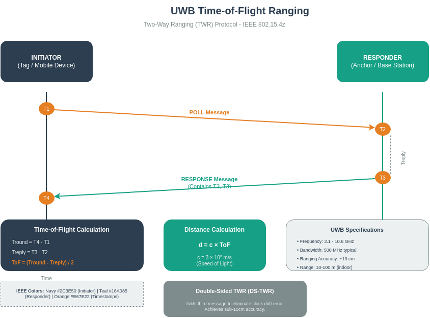
UWB achieves centimeter-level accuracy through nanosecond-precision time-of-flight measurements. The wide bandwidth (500 MHz+) enables sharp pulse timing that GPS and Wi-Fi cannot match indoors.
This editable DrawIO template can be customized for your specific UWB deployment documentation and presentations.
1045.7 Common Pitfalls in UWB Implementations
The Mistake: Installing 4 UWB anchors along a single wall or in a linear arrangement, then wondering why position accuracy is poor or positions “jump” unpredictably.
Why It Happens: Linear placement seems simpler for cabling and installation. Designers don’t realize that geometric diversity is essential for trilateration accuracy.
The Fix: UWB anchors must be spread across the space with geometric diversity - never collinear. For 2D positioning, place anchors in a rectangle or triangle pattern around the tracking area. For 3D positioning, vary anchor heights (floor, ceiling, mid-wall). Poor geometry leads to high GDOP (Geometric Dilution of Precision), where small ranging errors translate to large position errors. Aim for each tracked point to have 4+ anchors visible with good angular separation (>30 degrees between any two anchors from the tag’s perspective).
The Mistake: Deploying UWB in environments with metal shelving, water pipes, or dense equipment without accounting for signal blockage, then blaming the technology when accuracy degrades from 10cm to 2+ meters.
Why It Happens: UWB marketing emphasizes “centimeter accuracy” without caveats. Developers test in open labs, then deploy in cluttered warehouses or hospitals where obstructions are everywhere.
The Fix: UWB requires line-of-sight or soft NLOS (drywall, glass) for best accuracy. Metal, water, and dense concrete severely attenuate or block signals. Survey the deployment environment and identify obstruction zones. Use redundant anchors (6-8 instead of minimum 4) so tags always see enough anchors. Implement NLOS detection algorithms that identify and reject corrupted ranging measurements. For challenging environments, combine UWB with IMU (inertial measurement unit) data using sensor fusion to bridge NLOS gaps.
The Mistake: Implementing Two-Way Ranging (TWR) for a system with 500+ tags, then discovering the network can’t sustain the required update rate as tag count increases.
Why It Happens: TWR is simpler to implement (no anchor synchronization required), so it’s the default choice for prototypes. The prototype works with 10 tags, so developers assume it scales linearly.
The Fix: TWR requires each tag to exchange multiple messages with each anchor, consuming airtime proportional to (tags x anchors). For large deployments (>50 tags), use TDoA (Time Difference of Arrival) instead. In TDoA, each tag transmits a single blink, and synchronized anchors measure arrival times - airtime scales linearly with tag count, not quadratically. The trade-off is infrastructure complexity (anchors need precise time synchronization via wired network or GPS), but TDoA scales to thousands of tags with high update rates.
1045.8 Knowledge Check
1045.9 Hands-On Lab: UWB Ranging Simulation
1045.9.1 Lab Setup
This lab simulates UWB ranging concepts using an ESP32. While real UWB uses specialized chips (like DW3000), this simulation demonstrates the mathematical principles of TWR and trilateration that underpin all UWB positioning systems.
1045.9.2 Pre-Built Simulation Code
The simulation includes: - 4 Virtual Anchors: Placed at known positions (corners of 10m x 10m space) - 1 Virtual Tag: Mobile device being tracked - TWR Protocol: Simulated message exchange with realistic timing - Trilateration: Calculate tag position from ranges to 4 anchors - Error Simulation: Add timing jitter to show real-world effects - OLED Display: Visualize tag position and ranging data
#include <Wire.h>
#include <Adafruit_GFX.h>
#include <Adafruit_SSD1306.h>
#include <math.h>

// OLED display configuration
#define SCREEN_WIDTH 128
#define SCREEN_HEIGHT 64
#define OLED_RESET -1
Adafruit_SSD1306 display(SCREEN_WIDTH, SCREEN_HEIGHT, &Wire, OLED_RESET);

// UWB Constants
const float SPEED_OF_LIGHT = 299792458.0;  // m/s
const float UWB_TIMING_PRECISION = 65e-12; // 65 picoseconds (500 MHz bandwidth)
const int NUM_ANCHORS = 4;

// Anchor positions (in meters) - corners of 10m x 10m space
struct Anchor {
  float x, y;
  char id;
};

Anchor anchors[NUM_ANCHORS] = {
  {0.0, 0.0, 'A'},   // Bottom-left
  {10.0, 0.0, 'B'},  // Bottom-right
  {10.0, 10.0, 'C'}, // Top-right
  {0.0, 10.0, 'D'}   // Top-left
};

// Tag state
struct Tag {
  float actual_x, actual_y;      // True position (for simulation)
  float estimated_x, estimated_y; // Trilateration result
  float ranges[NUM_ANCHORS];      // Measured ranges to each anchor
  bool ranging_active;
} tag;

// TWR timing structure
struct TWRMeasurement {
  unsigned long T1; // Tag sends poll (nanoseconds)
  unsigned long T2; // Anchor receives poll
  unsigned long T3; // Anchor sends response
  unsigned long T4; // Tag receives response
};

// Simulation parameters
float timing_jitter = 0.2;  // nanoseconds (adjustable for accuracy demo)
int current_anchor = 0;
unsigned long last_update = 0;
int animation_phase = 0;

// Button pins for interactive control
#define BUTTON_INCREASE_JITTER 13
#define BUTTON_DECREASE_JITTER 12
#define BUTTON_RESET_STATS 14
#define BUTTON_CHANGE_MODE 27

// Simulation modes
enum SimMode {
  MODE_NORMAL,      // Tag moves in circle
  MODE_STATIC,      // Tag stays at center
  MODE_RANDOM,      // Tag moves randomly
  MODE_POOR_GDOP    // Anchors in poor geometry
};
SimMode current_mode = MODE_NORMAL;

// Statistics tracking
struct Statistics {
  float avg_range_error;
  float avg_position_error;
  float max_position_error;
  int num_samples;
  float gdop;  // Geometric Dilution of Precision
} stats;

// ... (Full code available in lab simulation)
1045.9.3 Understanding the Code
Key Components:
- Anchor Configuration: 4 anchors at known positions forming a 10m x 10m square
- Each anchor has x, y coordinates and an identifier (A-D)
- Backup anchors allow switching between good and poor geometry
- In POOR_GDOP mode, anchors become collinear to demonstrate geometry impact
- TWR Protocol Simulation (
performTWRfunction):- T1: Tag transmits poll at time 0
- T2: Anchor receives poll (T1 + time-of-flight + jitter)
- T3: Anchor transmits response (T2 + 100ns processing delay)
- T4: Tag receives response (T3 + time-of-flight + jitter)
- RTT = (T4 - T1) - (T3 - T2)
- Distance = RTT × c / 2
- Timing jitter simulates real-world clock drift and noise
- Trilateration Algorithm (
calculatePositionfunction):- Solves system of circle equations: (x-x_i)² + (y-y_i)² = r_i²
- Uses linearized least-squares approach with 3 anchors
- Fourth anchor provides redundancy for error checking
- Detects degenerate geometry (collinear anchors) and warns user
- GDOP Calculation (
calculateGDOPfunction):- Builds geometry matrix H from anchor-to-tag unit vectors
- Computes H^T × H and its determinant
- GDOP = sqrt(trace / determinant)
- Low GDOP (< 2.0) indicates good geometry, high GDOP (> 5.0) indicates poor geometry
- Interactive Controls:
- GPIO13: Increase timing jitter (simulate poor clock quality)
- GPIO12: Decrease timing jitter (simulate better clock quality)
- GPIO14: Reset statistics to start fresh measurement session
- GPIO27: Cycle through simulation modes (Normal, Static, Random, Poor GDOP)
1045.9.4 Challenge Exercises
1045.9.5 Expected Outcomes
After completing this lab, you should observe:
- TWR Distance Calculation:
- Round-trip time accurately measures distance
- Sub-centimeter ranging accuracy with good timing precision
- Timing jitter directly impacts ranging error
- Trilateration Position Fix:
- 4 anchors provide redundant 2D position solution
- Position accuracy depends on geometric dilution of precision (GDOP)
- Good anchor geometry (spread out, not collinear) is critical
- Error Propagation:
- Ranging errors of ±5cm can produce position errors of ±10-15cm
- GDOP amplifies ranging errors in poor geometry
- More anchors improve robustness but require careful placement
- Real-Time Performance:
- ESP32 can perform TWR calculations at 10+ Hz update rate
- Trilateration computation is lightweight (~1ms per fix)
- Suitable for real-time tracking applications
1045.9.6 Connection to UWB Theory
This lab demonstrates the core principles of commercial UWB systems:
- Time-of-Flight: Speed of light × time = distance (fundamental ranging principle)
- TWR Protocol: Eliminates clock synchronization requirement between devices
- Trilateration: Geometric solution to position from multiple ranges
- GDOP: Why anchor placement matters for accuracy
- Error Budget: How timing precision translates to position accuracy
Real UWB systems (DW3000, NXP Trimension) use the same mathematics but with: - 500+ MHz bandwidth for sub-nanosecond timing - Specialized RF front-ends for clean pulse transmission - IEEE 802.15.4z security features (STS) - Dedicated hardware accelerators for real-time processing
Design a UWB positioning system for a specific application:
- Choose an environment (office, warehouse, hospital, retail store, manufacturing floor)
- Define requirements (accuracy, update rate, number of assets)
- Calculate anchor count and placement
- Select TWR vs TDoA and justify
- Estimate total system cost
- Identify key challenges and mitigation strategies
Share your design for feedback in the course forums!
1045.10 Summary
UWB enables unique applications requiring centimeter-level precision and secure ranging. From automotive digital keys to warehouse asset tracking, UWB’s combination of accuracy and security makes it the technology of choice for critical positioning applications.
Key Takeaways:
Applications: Automotive (digital keys), logistics (asset tracking), smart home (spatial awareness), industrial (safety zones), healthcare (equipment tracking)
Security: IEEE 802.15.4z STS provides cryptographic protection; time-of-flight physics prevents relay attacks
Cost Model: Enterprise deployments typically $4-8 per m² with 12-18 month ROI
Pitfalls: Avoid collinear anchors, account for NLOS conditions, use TDoA for large deployments
Hands-On: TWR protocol and trilateration can be simulated to understand core positioning principles
1045.12 What’s Next?
Now that you understand Ultra-Wideband technology for precise positioning, consider exploring:
- Bluetooth: Learn how BLE 5.1 Angle of Arrival compares to UWB for different use cases
- LPWAN Technologies: When range matters more than precision, explore long-range options
- Network Design: Apply UWB in complete system designs with simulation and validation