605 ADC/DAC Worked Examples
605.1 Learning Objectives
By the end of this section, you will be able to:
- Calculate ADC Output: Convert voltage input to digital values
- Design Voltage Dividers: Create sensor interface circuits
- Analyze Quantization Error: Determine measurement precision limits
- Apply Nyquist Calculations: Size sampling rates for specific signals
- Configure DAC Output: Generate specific voltages from digital values
- Implement Gamma Correction: Apply perceptually-correct LED dimming
605.2 Prerequisites
Before diving into this chapter, you should be familiar with:
- ADC Fundamentals: Understanding of ADC operation and resolution
- Nyquist Sampling Theory: Understanding of sampling rate requirements
- Binary Fundamentals: Binary number systems and powers of 2
605.3 ADC Conversion Formula
The fundamental ADC conversion formula relates analog input voltage to digital output value:
\[\text{Digital Output} = \left\lfloor \frac{V_{in}}{V_{ref}} \times (2^n - 1) \right\rfloor\]
Where: - \(V_{in}\) = Analog input voltage (volts) - \(V_{ref}\) = Reference voltage (maximum measurable voltage) - \(n\) = ADC resolution (number of bits) - \(\lfloor \rfloor\) = Floor function (round down to nearest integer)
605.4 Worked Example 1: Temperature Sensor (10-bit ADC)
Given: - ADC Resolution: 10 bits (Arduino Uno) - \(V_{ref}\) = 3.3V - \(V_{in}\) = 1.65V (sensor output at 25C)
Calculate Digital Output:
\[\text{Digital Output} = \left\lfloor \frac{1.65V}{3.3V} \times (2^{10} - 1) \right\rfloor\]
\[= \left\lfloor 0.5 \times 1023 \right\rfloor\]
\[= \left\lfloor 511.5 \right\rfloor\]
\[= 512\]
Result: The ADC outputs 512 (binary: 1000000000)
Verification: - 512 is exactly half of 1023, which matches \(V_{in}\) being half of \(V_{ref}\) - This digital value would be read by analogRead(A0) as 512
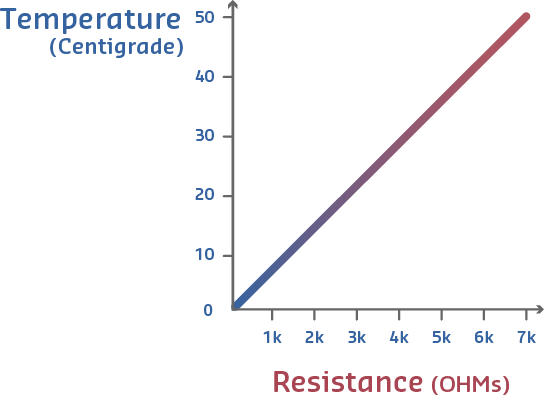
605.5 Worked Example 2: LM35 Temperature Sensor
The LM35 is a popular precision temperature sensor that outputs 10mV per degree Celsius.
LM35 Specifications: - Output: 10mV/C - Temperature Range: 0-100C - Voltage Range: 0-1.0V
Scenario: Measuring room temperature (25C) with 10-bit ADC
Step 1: Calculate Sensor Output Voltage
\[V_{sensor} = \text{Temperature} \times 10\text{mV/C}\]
\[V_{sensor} = 25C \times 10\text{mV/C} = 250\text{mV} = 0.250V\]
Step 2: ADC Configuration
For optimal resolution with 0-1V sensor range: - Use \(V_{ref}\) = 1.0V (external reference or ATmega internal 1.1V) - Resolution: 10-bit → 1024 discrete values
Step 3: Calculate Digital Output
\[\text{Digital Output} = \left\lfloor \frac{0.250V}{1.0V} \times 1023 \right\rfloor\]
\[= \left\lfloor 255.75 \right\rfloor = 256\]
Step 4: Calculate Resolution (Temperature per ADC Count)
\[\text{Resolution} = \frac{\text{Temperature Range}}{\text{ADC Counts}} = \frac{100C}{1024} = 0.0977C \text{ per count}\]
This means each ADC step represents approximately 0.1C change.
Step 5: Convert ADC Reading Back to Temperature
\[\text{Temperature} = \frac{\text{ADC Value}}{1024} \times 100C\]
\[\text{Temperature} = \frac{256}{1024} \times 100C = 25.0C\]
Key Insight: By matching \(V_{ref}\) to sensor range (1V instead of 5V), we maximize resolution and minimize wasted ADC range.
Comparison: 5V Reference vs 1V Reference
| Configuration | Resolution | Wasted Range | Temperature Precision |
|---|---|---|---|
| 5V Vref | 4.88mV/count | 80% (1V used, 4V unused) | 0.488C/count |
| 1V Vref | 0.977mV/count | 0% (1V used, 1V available) | 0.098C/count |
Using 1V reference gives 5x better temperature resolution by fully utilizing ADC range!
605.6 Worked Example 3: Quantization Error Analysis
Quantization error is the inherent inaccuracy introduced when converting continuous analog signals to discrete digital values.
Quantization Error Formula:
\[\text{Max Error} = \pm \frac{1}{2} \text{LSB} = \pm \frac{V_{ref}}{2^{n+1}}\]
Where LSB (Least Significant Bit) is the smallest voltage change the ADC can detect.
10-bit ADC with 3.3V Reference:
\[\text{LSB Step Size} = \frac{3.3V}{2^{10}} = \frac{3.3V}{1024} = 3.22\text{mV}\]
\[\text{Max Quantization Error} = \pm \frac{3.22\text{mV}}{2} = \pm 1.61\text{mV}\]
What This Means: - Any voltage between 1.648V and 1.652V will round to the same digital value (512) - Worst-case error: +/-1.61mV from actual voltage
Comparison Across ADC Resolutions:
| Resolution | LSB Step (3.3V) | Max Error | Example Use Case |
|---|---|---|---|
| 8-bit | 12.9mV | +/-6.45mV | Low-cost light sensors |
| 10-bit | 3.22mV | +/-1.61mV | Arduino Uno (general purpose) |
| 12-bit | 0.805mV | +/-0.403mV | ESP32 (precision sensors) |
| 16-bit | 0.0503mV | +/-0.0252mV | Thermocouples, strain gauges |
Reducing Quantization Error:
- Use Higher Resolution ADC
- 12-bit vs 10-bit: 4x reduction in error (1.61mV → 0.403mV)
- 16-bit vs 10-bit: 64x reduction in error
- Oversampling and Averaging
- Average N samples to gain extra resolution
- Effective bits increase by log2(N)/2
- Example: Average 16 samples with 10-bit ADC → 12-bit effective resolution
- Match Vref to Signal Range
- If measuring 0-1V signal, use 1V reference (not 3.3V or 5V)
- Maximizes use of ADC’s available range
605.7 Worked Example 4: Nyquist Theorem - Audio Sampling
Given: - Human voice frequency range: 300 Hz to 3.4 kHz - Highest frequency: \(f_{max}\) = 3.4 kHz
Calculate Minimum Sampling Rate:
\[f_{sample} \geq 2 \times 3400\text{ Hz} = 6800\text{ Hz}\]
Practical Implementation: - Telephone systems: 8 kHz (provides margin above 6.8 kHz minimum) - VoIP codecs: 8-16 kHz - Audio recording: 44.1-48 kHz (for full 20 kHz human hearing range)
605.8 Worked Example 5: Accelerometer - Vibration Monitoring
Given: - Machine vibration events: 0-100 Hz - Highest frequency: \(f_{max}\) = 100 Hz
Calculate Minimum Sampling Rate:
\[f_{sample} \geq 2 \times 100\text{ Hz} = 200\text{ Hz}\]
Practical Implementation: - Industrial IoT: 500-1000 Hz (2.5-5x oversampling for safety margin) - Allows detection of unexpected high-frequency faults - Ensures anti-aliasing filter has gradual roll-off
Real-World Sampling Rates:
| Application | Signal Bandwidth | Nyquist Minimum | Practical Rate | Oversampling Factor |
|---|---|---|---|---|
| Audio (telephone) | 3.4 kHz | 6.8 kHz | 8 kHz | 1.2x (minimal) |
| Audio (music) | 20 kHz | 40 kHz | 44.1-48 kHz | 1.1-1.2x |
| Accelerometer | 100 Hz | 200 Hz | 500-1000 Hz | 2.5-5x |
| ECG (heartbeat) | 150 Hz | 300 Hz | 500-1000 Hz | 1.7-3.3x |
| Ultrasonic distance | 40 kHz | 80 kHz | 200 kHz+ | 2.5x |
605.9 Worked Example 6: Soil Moisture Sensor (ESP32)
Scenario: A smart irrigation system uses a capacitive soil moisture sensor that outputs 1.2V (dry) to 2.8V (saturated). You need to determine optimal ADC configuration on an ESP32 to detect 1% moisture changes for water-efficient farming.
Given: - Sensor output range: 1.2V (dry/0%) to 2.8V (saturated/100%) - ESP32 ADC: 12-bit, configurable attenuation (0dB, 2.5dB, 6dB, 11dB) - Moisture measurement range: 0-100% - Required resolution: 1% moisture change detection
Steps:
Calculate voltage per percent moisture: \[\Delta V = \frac{V_{max} - V_{min}}{\text{Moisture Range}} = \frac{2.8V - 1.2V}{100\%} = 16mV/\%\]
Determine required ADC resolution:
- To detect 1% change, need LSB < 16mV
- With 11dB attenuation: range = 0-3.6V, LSB = 3.6V/4096 = 0.88mV (sufficient)
- With 6dB attenuation: range = 0-2.2V (cannot read 2.8V - too narrow)
- Select 11dB attenuation (0-3.6V range covers sensor output)
Calculate actual resolution achieved: \[\text{ADC steps per } 1\% = \frac{16mV}{0.88mV} = 18.2 \text{ steps}\]
- Theoretical moisture resolution: 1/18.2 = 0.055% per ADC step
Account for ESP32 ADC nonlinearity:
- ESP32 ADC has known nonlinearity at extremes (0-0.1V and >3.0V)
- Sensor range (1.2-2.8V) falls in linear region - acceptable
- Consider factory calibration values in eFuse for better accuracy
Implement oversampling for noise reduction:
- Average 64 samples to gain ~3 effective bits
- Effective resolution: 12 + 3 = 15 bits equivalent
- New moisture resolution: 0.055% / 8 = 0.007% per averaged reading
Result: - Raw ADC values: 1365 (dry) to 3185 (saturated) with 11dB attenuation - Moisture formula: moisture_percent = (adc_value - 1365) / 18.2 - With 64-sample averaging: <0.01% moisture resolution
Key Insight: Proper attenuation selection is critical. Using 0dB attenuation (0-1.1V range) would clip the signal, while 11dB provides headroom. The ESP32’s ADC nonlinearity is most pronounced at range extremes - design sensor output to fall in the 0.5-2.5V linear region when possible.
605.10 Worked Example 7: Ultrasonic Distance Measurement
Scenario: An autonomous robot uses an HC-SR04 ultrasonic sensor for obstacle detection. The echo pulse width (10us to 25ms) must be measured accurately. You need to determine if ADC-based measurement or timer-based capture is appropriate.
Given: - HC-SR04 echo pulse: 10us (2cm) to 25ms (4m) - Speed of sound: 343 m/s at 20C - Required distance accuracy: 1cm - ESP32 ADC sampling rate: 2 MSPS maximum (but limited in practice) - ESP32 timer resolution: 12.5ns (80MHz clock)
Steps:
Calculate time per centimeter of distance: \[t_{1cm} = \frac{2 \times 0.01m}{343 m/s} = 58.3\mu s\] (Factor of 2 because sound travels to object and back)
Evaluate ADC-based approach:
- If we sample analog echo signal at 100kHz: 10us between samples
- Time resolution: 10us corresponds to 0.17cm
- Problem: HC-SR04 outputs digital pulse, not analog - ADC not appropriate
Evaluate timer-based approach (correct method):
- ESP32 timer at 80MHz: 12.5ns resolution
- Theoretical distance resolution: 0.5 x 343 m/s x 12.5ns = 0.002mm
- Far exceeds 1cm requirement
Implement with pulseIn() timing:
duration_us = pulseIn(ECHO_PIN, HIGH);  // Measures pulse width
distance_cm = duration_us / 58.3;       // Convert to distance
Consider temperature compensation:
- Speed of sound: \(v = 331.3 + 0.606 \times T_{celsius}\) m/s
- At 0C: v = 331.3 m/s (time factor = 60.3 us/cm)
- At 40C: v = 355.5 m/s (time factor = 56.2 us/cm)
- 7% error if temperature not compensated over 0-40C range
Result: - Use hardware timer capture, not ADC, for pulse width measurement - Distance calculation: distance_cm = duration_us * speed_of_sound / 20000 - With temperature compensation: <1cm accuracy achievable
Key Insight: ADCs are for converting analog voltage levels to digital values. For timing measurements (pulse width, frequency), use hardware timers or input capture peripherals.
605.11 Worked Example 8: DAC Motor Speed Control (8-bit)
Given: - DAC Resolution: 8 bits (0-255) - \(V_{ref}\) = 5V - Motor controller accepts 0-5V (0V = stopped, 5V = full speed)
DAC Formula:
\[V_{out} = V_{ref} \times \frac{\text{Digital Input}}{2^n - 1}\]
Calculate Output Voltages:
| Speed Setting | Digital Input | Calculation | DAC Output | Motor Speed |
|---|---|---|---|---|
| Stopped | 0 | \(5V \times \frac{0}{255}\) | 0.00V | 0% |
| 25% Speed | 64 | \(5V \times \frac{64}{255}\) | 1.25V | 25% |
| 50% Speed | 128 | \(5V \times \frac{128}{255}\) | 2.51V | 50% |
| 75% Speed | 192 | \(5V \times \frac{192}{255}\) | 3.76V | 75% |
| Full Speed | 255 | \(5V \times \frac{255}{255}\) | 5.00V | 100% |
Arduino Code Example:
// Control motor speed with DAC output
int speed_percent = 50; // 50% speed
int dac_value = map(speed_percent, 0, 100, 0, 255);

// On ESP32 with built-in DAC (8-bit):
dacWrite(DAC1, dac_value); // Outputs 2.51V (50% of 5V)
605.12 Worked Example 9: LED Dimming with Gamma Correction
Human eyes perceive brightness logarithmically, not linearly. A “50% brightness” setting needs gamma correction.
Linear DAC (appears too bright): - 50% digital value (128/255) → 2.5V → appears ~75% bright to human eye
Gamma-Corrected DAC (perceptually accurate):
\[\text{Corrected Value} = \left(\frac{\text{Desired Brightness}}{100}\right)^{2.2} \times 255\]
For 50% perceived brightness:
\[\text{Corrected Value} = \left(\frac{50}{100}\right)^{2.2} \times 255 = (0.5)^{2.2} \times 255 = 0.2176 \times 255 = 55\]
Comparison:
| Desired Brightness | Linear DAC Value | Perceived Brightness | Gamma-Corrected DAC | Perceived Brightness |
|---|---|---|---|---|
| 25% | 64 | ~45% (too bright) | 18 | 25% |
| 50% | 128 | ~75% (too bright) | 55 | 50% |
| 75% | 192 | ~90% (too bright) | 128 | 75% |
Arduino Gamma Correction Code:
// Gamma correction lookup table (saves computation)
const uint8_t gamma8[] = {
    0,  0,  0,  0,  0,  1,  1,  1,  1,  2,  2,  2,  3,  3,  4,  4,
    5,  5,  6,  7,  8,  8,  9, 10, 11, 12, 13, 15, 16, 17, 18, 20,
   21, 23, 24, 26, 28, 30, 32, 34, 36, 38, 40, 43, 45, 48, 50, 53,
   56, 59, 62, 65, 68, 71, 75, 78, 82, 85, 89, 93, 97,101,105,110,
  114,119,123,128,133,138,143,149,154,160,165,171,177,183,189,195,
  202,208,215,222,229,236,243,250,255 // ... (256 values total)
};

void setLEDBrightness(int percent) {
    int linear = map(percent, 0, 100, 0, 255);
    int corrected = gamma8[linear]; // Apply gamma correction
    analogWrite(LED_PIN, corrected); // PWM output
}
605.13 Knowledge Check Quiz
605.14 Summary
This chapter provided step-by-step worked examples for ADC and DAC calculations:
- ADC Conversion Formula: Digital Output = floor((Vin / Vref) x (2^n - 1))
- Temperature Sensor: Match Vref to sensor range for optimal resolution
- Quantization Error: +/-(Vref / 2^(n+1)) is the inherent measurement uncertainty
- Nyquist Calculations: f_sample >= 2 x f_max for accurate digitization
- DAC Output: V_out = Vref x (Digital Input / (2^n - 1))
- Gamma Correction: Apply non-linear mapping for perceptually-correct LED dimming
- Real-World Applications: Soil moisture, ultrasonic distance, motor control
These formulas and examples form the practical foundation for sensor interfacing in IoT systems.
605.15 What’s Next?
Now continue to learn about Digital-to-Analog Converters (DACs) and PWM output for actuator control.
Continue to DAC and PWM Output →
In This Series: - Binary Fundamentals - Binary number systems - ADC Fundamentals - How ADCs convert analog to digital - Nyquist Sampling Theory - Sampling rate requirements - DAC and PWM Output - Digital-to-analog conversion
Labs: - Sensor Labs - Hands-on practice