595  Semiconductors, Doping, and Diodes

595.1 Semiconductors: The Foundation of Electronics

⏱️ ~20 min | ⭐⭐ Intermediate | 📋 P06.C05.U02

595.1.1 Pure Semiconductors

Common Materials: - Silicon (Si) - 95% of all semiconductors - Germanium (Ge) - Historical use, now rare - Gallium Arsenide (GaAs) - High-frequency applications

Pure semiconductors aren’t very useful because they don’t conduct well at room temperature.

Artistic illustration of atomic structure showing: central nucleus containing protons (positive charge, red) and neutrons (neutral, gray), electron shells (K, L, M, N) at increasing distances from nucleus with electrons (negative charge, blue) orbiting in quantized energy levels, and valence electrons in the outermost shell determining chemical and electrical properties of the element.

Atomic Structure Artistic Visualization

Understanding atomic structure helps explain why silicon (4 valence electrons) makes an ideal semiconductor material.

595.1.2 Doping: Creating Useful Semiconductors

Doping = Adding impurities (dopants) to semiconductors to control conductivity

%%{init: {'theme': 'base', 'themeVariables': { 'primaryColor': '#2C3E50', 'primaryTextColor': '#fff', 'primaryBorderColor': '#1A252F', 'lineColor': '#2C3E50', 'secondaryColor': '#16A085', 'tertiaryColor': '#E67E22', 'noteTextColor': '#2C3E50', 'noteBkgColor': '#ECF0F1', 'textColor': '#2C3E50', 'fontSize': '16px'}}}%%
flowchart TD
    PURE["Pure Silicon<br/>(4 valence electrons)<br/>Poor conductor"]

    PURE --> NTYPE["N-Type Doping<br/>Add Phosphorus (5e⁻)<br/>Extra electrons"]
    PURE --> PTYPE["P-Type Doping<br/>Add Boron (3e⁻)<br/>Missing electrons (holes)"]

    NTYPE --> NRESULT["N-Type Semiconductor<br/>Majority: Electrons (-)<br/>Minority: Holes (+)"]

    PTYPE --> PRESULT["P-Type Semiconductor<br/>Majority: Holes (+)<br/>Minority: Electrons (-)"]

    style PURE fill:#7F8C8D,stroke:#5D6D7E,color:#fff
    style NTYPE fill:#16A085,stroke:#138D75,color:#fff
    style PTYPE fill:#E67E22,stroke:#D35400,color:#fff
    style NRESULT fill:#ECF0F1,stroke:#16A085,color:#2C3E50
    style PRESULT fill:#ECF0F1,stroke:#E67E22,color:#2C3E50

Figure 595.1: Semiconductor Doping Process: Creating N-Type and P-Type Materials

{fig-alt=“Electronics diagram illustrating”Pure Silicon (4 valence electrons) Poor conductor”, “N-Type Doping Add Phosphorus (5e⁻) Extra electrons”, “P-Type Doping Add Boron (3e⁻) Missing electrons (holes)” showing semiconductor components, transistor circuits, diode operation, signal amplification, or switching circuits used in sensor and actuator interfacing for IoT systems.”}

Doping process showing how pure silicon (4 valence electrons) is transformed into N-type semiconductor by adding phosphorus dopant (5 valence electrons creating excess electrons) or P-type semiconductor by adding boron dopant (3 valence electrons creating holes). N-type has electrons as majority carriers, P-type has holes as majority carriers, enabling controllable conductivity for transistors and diodes.

Figure 595.2

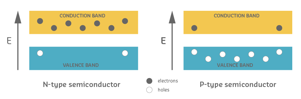
595.2 N-type and P-type Semiconductors

⏱️ ~20 min | ⭐⭐ Intermediate | 📋 P06.C05.U03

595.2.1 N-type (Negative)

Doping: Add elements with extra electrons (e.g., Phosphorus)

Result: Excess of free electrons (negative charge carriers)

Silicon atom: 4 valence electrons
Phosphorus dopant: 5 valence electrons → 1 extra electron!

Properties: - Majority carriers: Electrons (-) - Minority carriers: Holes (+) - Better conductivity than pure silicon

595.2.2 P-type (Positive)

Doping: Add elements with fewer electrons (e.g., Boron)

Result: Deficit of electrons creates “holes” (positive charge carriers)

Silicon atom: 4 valence electrons
Boron dopant: 3 valence electrons → 1 missing electron (hole)!

Properties: - Majority carriers: Holes (+) - Minority carriers: Electrons (-) - Holes act as positive charge carriers

Energy band diagram comparing N-type and P-type semiconductors showing conduction and valence bands with electrons (filled circles) as majority carriers in N-type concentrated in the conduction band, and holes (empty circles) as majority carriers in P-type concentrated in the valence band, with energy level E on vertical axis
Figure 595.3: N-type vs P-type semiconductor energy band diagram showing electron and hole distributions

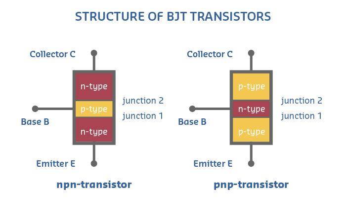
595.2.3 Transistor Types Overview

Understanding the different transistor families helps you select the right component for IoT applications:

%%{init: {'theme': 'base', 'themeVariables': { 'primaryColor': '#2C3E50', 'primaryTextColor': '#fff', 'primaryBorderColor': '#1A252F', 'lineColor': '#2C3E50', 'secondaryColor': '#16A085', 'tertiaryColor': '#E67E22', 'noteTextColor': '#2C3E50', 'noteBkgColor': '#ECF0F1', 'textColor': '#2C3E50', 'fontSize': '16px'}}}%%
graph TD
    ROOT["Transistors<br/>3-Layer Semiconductors"]

    ROOT --> BJT["BJT<br/>Bipolar Junction<br/>Transistor"]
    ROOT --> FET["FET<br/>Field Effect<br/>Transistor"]

    BJT --> NPN["NPN<br/>Current-controlled<br/>β = 50-300"]
    BJT --> PNP["PNP<br/>Current-controlled<br/>β = 50-300"]

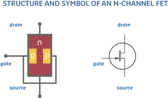
    FET --> JFET["JFET<br/>Junction FET<br/>Always-on"]
    FET --> MOSFET["MOSFET<br/>Metal-Oxide FET<br/>Voltage-controlled"]

    MOSFET --> NMOS["N-Channel<br/>Low-side switch<br/>Rds(on) < 100mΩ"]
    MOSFET --> PMOS["P-Channel<br/>High-side switch<br/>Rds(on) > 100mΩ"]

    NPN --> NPNAPP["Applications:<br/>Low-side switching<br/>Signal amplification<br/>Darlington pairs"]

    PNP --> PNPAPP["Applications:<br/>High-side switching<br/>Complementary pairs<br/>Current sources"]

    NMOS --> NMOSAPP["Applications:<br/>Motor drivers<br/>Power switching<br/>90% of IoT usage"]

    PMOS --> PMOSAPP["Applications:<br/>Load switching<br/>Reverse polarity protection<br/>Battery disconnect"]

    style ROOT fill:#2C3E50,stroke:#1A252F,color:#fff
    style BJT fill:#E67E22,stroke:#D35400,color:#fff
    style FET fill:#16A085,stroke:#138D75,color:#fff
    style NPN fill:#ECF0F1,stroke:#E67E22,color:#2C3E50
    style PNP fill:#ECF0F1,stroke:#E67E22,color:#2C3E50
    style JFET fill:#ECF0F1,stroke:#16A085,color:#2C3E50
    style MOSFET fill:#ECF0F1,stroke:#16A085,color:#2C3E50
    style NMOS fill:#ECF0F1,stroke:#16A085,color:#2C3E50
    style PMOS fill:#ECF0F1,stroke:#16A085,color:#2C3E50
    style NPNAPP fill:#FEF5E7,stroke:#E67E22,color:#2C3E50
    style PNPAPP fill:#FEF5E7,stroke:#E67E22,color:#2C3E50
    style NMOSAPP fill:#E8F6F3,stroke:#16A085,color:#2C3E50
    style PMOSAPP fill:#E8F6F3,stroke:#16A085,color:#2C3E50

Figure 595.4: Transistor Types Taxonomy: BJT vs FET Architectures and Applications

{fig-alt=“Electronics diagram illustrating”Transistors 3-Layer Semiconductors”, “BJT Bipolar Junction Transistor”, “FET Field Effect Transistor” showing semiconductor components, transistor circuits, diode operation, signal amplification, or switching circuits used in sensor and actuator interfacing for IoT systems.”}

Transistor types taxonomy showing two main families: BJT (Bipolar Junction Transistors) are current-controlled devices with NPN and PNP types offering current gain β=50-300, used for signal amplification and switching; FET (Field Effect Transistors) are voltage-controlled with JFET (always-on devices) and MOSFET (metal-oxide semiconductor) types, where N-channel MOSFETs dominate IoT applications (90% usage) for motor drivers and power switching with low on-resistance Rds(on)<100mΩ, while P-channel MOSFETs handle high-side switching and battery disconnect circuits.

Figure 595.5
Structure diagram of BJT transistors showing NPN transistor with N-type collector, P-type base, and N-type emitter layers forming two PN junctions, and PNP transistor with P-type collector, N-type base, and P-type emitter layers, with collector C, base B, and emitter E terminals labeled
Figure 595.6: Internal structure of NPN and PNP bipolar junction transistors showing semiconductor layer arrangement

BJT transistor modeled as two back-to-back diodes showing NPN configuration as two PN junctions with base-emitter and base-collector diodes, and PNP configuration with reversed diode orientations, alongside standard transistor schematic symbols for NPN and PNP types

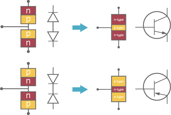
BJT transistor diode model showing NPN and PNP as two back-to-back PN junctions with schematic symbols

Artistic illustration of BJT transistor diode model showing NPN configuration as two back-to-back PN junctions with base-emitter forward diode and base-collector reverse diode, current flow paths, and corresponding schematic symbol with collector, base, and emitter terminals
(a) The BJT can be understood as two PN junctions sharing a common middle layer (base). In an NPN transistor, a small base current allows a much larger collector-emitter current to flow, providing current amplification essential for sensor signal conditioning and motor driver circuits.
Geometric diagram of MOSFET internal structure showing gate oxide layer, N-type source and drain regions, P-type body substrate, inversion channel formation under gate, and electron flow path when gate voltage exceeds threshold
(b) MOSFETs control drain-source current through gate voltage without significant gate current, making them ideal for microcontroller-driven switching. The insulated gate oxide provides high input impedance, allowing direct connection to GPIO pins for logic-level MOSFETs.
Artistic circuit diagram showing N-channel MOSFET used as low-side switch with gate connected to microcontroller GPIO through optional resistor, drain connected to load positive, source connected to ground, and flyback diode across inductive load
(c) This common switching circuit demonstrates N-channel MOSFET low-side switching, where the load connects between power supply and drain, with source grounded. The microcontroller GPIO controls gate voltage, turning the MOSFET on or off to switch high-current loads like motors and LEDs.
Figure 595.7
Structure and schematic symbol of N-channel FET showing N-type channel between drain and source terminals with P-type gate regions on either side controlling current flow, and the standard JFET schematic symbol with gate, drain, and source terminals labeled
Figure 595.8: Internal structure and schematic symbol of N-channel field effect transistor (FET)
NoteCross-Hub Connections

Explore More Electronics Resources:

  • Simulations Hub - Try interactive circuit simulators (TinkerCAD, Falstad) to build transistor switches and test diode circuits without physical components
  • Videos Hub - Watch visual explanations of semiconductor physics, PN junction behavior, and transistor operation at the atomic level
  • Quizzes Hub - Test your understanding of BJT vs MOSFET selection, power dissipation calculations, and circuit design decisions
  • Knowledge Gaps Hub - Clarify common confusions about gate drive voltage, current vs voltage control, and thermal management

Why This Matters: Electronics fundamentals connect to nearly every IoT topic. Understanding transistors enables you to design sensor interfaces (signal conditioning), control actuators (motor drivers), optimize power consumption (load switching), and troubleshoot hardware issues (thermal problems, shoot-through).

WarningCommon Misconception: “All MOSFETs Work with 3.3V/5V GPIO”

The Misconception: Many beginners assume any MOSFET can be driven directly from microcontroller GPIO pins (3.3V or 5V), leading to circuits that “sort of work” but run hot, waste power, and fail prematurely.

The Reality with Real Numbers: Standard MOSFETs require Vgs = 10-12V to fully turn ON and achieve their datasheet specifications. When driven with insufficient gate voltage, they operate in the linear region with dramatically higher on-resistance.

Real-World Impact (IRF540N Example): - Datasheet spec: Rds(on) = 44mΩ @ Vgs=10V - With 5V gate drive: Rds(on) = 200mΩ (4.5× higher!) - Switching 2A load: - Expected power: (2A)² × 0.044Ω = 0.18W (cool) - Actual power: (2A)² × 0.2Ω = 0.8W (hot!) - TO-220 package without heatsink: 1W max → MOSFET runs at 80°C → premature failure

Measured in Real Projects: A student designed a smart fan controller using IRF540N driven from 5V Arduino. Initial testing worked fine for 10 minutes, but after 30 minutes the MOSFET reached 95°C and the fan speed dropped 40% due to voltage drop across the partially-on MOSFET. After switching to IRLZ44N (logic-level), temperature dropped to 35°C and fan ran at full speed.

The Solution: Always check the Vgs specification in datasheets: - Logic-level MOSFETs: Vgs(th) < 2.5V, fully on at 4.5-5V (look for “L” in part number: IRLZ44N) - Standard MOSFETs: Vgs(th) = 2-4V, but require 10V for rated Rds(on)

Cost of This Mistake: - Wasted heat: 0.8W - 0.18W = 0.62W continuous loss - Battery life: For a 2A load running 50% duty cycle, that’s 7.4Wh/day wasted → 1000mAh battery dies 3× faster - Component damage: Thermal stress reduces MOSFET lifetime from 100,000 hours to <10,000 hours - Debugging time: Students typically spend 2-4 hours troubleshooting “hot MOSFET” before discovering gate voltage issue

Key Takeaway: When selecting MOSFETs for microcontroller projects, ALWAYS verify Rds(on) at YOUR gate voltage (not the datasheet headline spec). Add 50% safety margin for thermal calculations. Logic-level MOSFETs cost the same ($0.50) but save hours of debugging and prevent field failures.

595.3 Knowledge Check

Test your understanding with these questions.

Question 6: You’re reverse-engineering a commercial IoT smart plug. The teardown reveals the main switching device is a triac, not a MOSFET. The product switches 120V AC mains at 15A. Why use a triac?

💡 Explanation: Triacs are specialized bidirectional AC switches perfect for controlling mains AC power. Why not MOSFETs for AC: (1) MOSFETs are unidirectional (body diode conducts in reverse), requiring full H-bridge (4 MOSFETs) to switch AC, (2) High-voltage MOSFETs (>500V for 120V AC) have high Rds(on) causing losses, (3) Gate drive complexity: need isolated power supplies for high-side MOSFETs. Triac advantages: Single device handles both half-cycles, BTA16-600 (16A, 600V) easily handles 15A at 120V, simple low-power gate trigger (~10mA) via optocoupler for isolation. Cost: BTA16-600 triac = $0.50 vs MOSFET bridge = $5-10. Typical circuit: ESP32 → MOC3021 optocoupler → triac → AC load (2500V isolation).

Question 6: Why is a flyback diode necessary when controlling a relay with a transistor?

💡 Explanation: Inductive loads (relays, motors, solenoids) store energy in magnetic fields. When switched OFF, this stored energy creates a voltage spike that can reach hundreds of volts, destroying the transistor. The flyback (freewheeling) diode provides a path for this current to circulate safely. Physics: V = -L × (dI/dt). When current through an inductor changes rapidly, it induces a large opposing voltage. Without a flyback diode, this voltage can be 10-100× the supply voltage, exceeding the transistor’s breakdown voltage and causing permanent damage. The flyback diode (typically 1N4007 or 1N4148) is connected in parallel with the inductive load, reverse-biased during normal operation. When the transistor turns OFF, the inductor’s voltage reverses, forward-biasing the diode and providing a safe current path. Essential for any IoT project controlling relays, solenoids, or DC motors.

Question 1: You’re designing an ESP32-based soil moisture sensor that must run on a coin cell battery for 2 years. The sensor needs to switch a 12V solenoid valve (100mA) to water plants. Which transistor type should you use?

💡 Explanation: N-channel MOSFET is the best choice for battery-powered IoT devices. BJTs require continuous base current to stay ON (1-5mA for 100mA load with β=100), consuming precious battery power. MOSFETs are voltage-controlled with essentially zero steady-state gate current. For a soil sensor that activates the valve 1× per day for 10 seconds, a BJT would waste 1mA × 24 hours = 24mAh/day just keeping the switch on, while a MOSFET draws virtually nothing. N-channel MOSFETs offer better performance than P-channel (lower Rds(on), higher current capability). Use low-side switching with the ESP32’s 3.3V GPIO directly driving the gate through a 100Ω resistor. Don’t forget a 1N4007 flyback diode across the solenoid!

Question 8: You’re testing a new batch of 2N2222 transistors. Datasheet specifies β=100 typical. Your measurements show β ranging from 75 to 250 across 20 samples. Your circuit design assumes β=100 exactly. What will happen?

💡 Explanation: β variation is normal and critical for robust design. Transistor β (current gain) varies widely: (1) Manufacturing tolerance: 2N2222 spec is β=75-300 (4× range!), (2) Temperature: β decreases ~50% from 25°C to 100°C, (3) Aging: β degrades over device lifetime. Design implications: If you calculate I_base = I_collector / β using “typical” β=100, transistors with actual β=75 won’t saturate fully (V_CE > 0.2V, causing heating). Transistors with β=250 oversaturate (wasting base current). Robust design practice: Use saturation factor 1.5-2.0: I_base = (1.5 to 2.0) × I_collector / β_min. For I_C=100mA with β_min=75, use I_base = 2.0 × 100mA / 75 = 2.67mA (not 1mA). This ensures saturation across all units, temperatures, and aging. Why MOSFETs are better: Gate threshold voltage variation is much smaller (Vgs(th) = 2-4V typ vs 1-4V range), and voltage-controlled behavior is less sensitive to parameter variation.

Question 3: You’re interfacing a 5V Arduino with a 3.3V ESP32 module. The Arduino’s GPIO outputs 5V HIGH, exceeding the ESP32’s 3.6V maximum. Which level-shifting circuit is MOST reliable for bidirectional communication?

💡 Explanation: MOSFET-based bidirectional level shifter is the gold standard for I²C, SPI, and UART interfacing. Circuit: BSS138 N-channel MOSFET with source to ground, gate to 3.3V side with 10kΩ pull-up, drain to 5V side with 10kΩ pull-up. Why alternatives fail: (A) Voltage divider only works unidirectionally and has high impedance causing slow rise times and noise susceptibility. (B) Diodes don’t provide bidirectional translation and forward voltage varies with temperature. (C) Series resistor provides NO voltage translation - 5V still reaches ESP32 input, damaging it over time. The BSS138 solution handles 50kHz-400kHz I²C perfectly, costs $0.10, and is used in commercial level-shifter modules.

Question 4: Your IoT weather station uses a 12V relay to control a heating element. When the relay turns OFF, you observe 300V voltage spikes destroying the transistor. You add a 1N4007 flyback diode but spikes persist at 50V. What’s wrong?

💡 Explanation: The flyback diode is installed backwards! Correct orientation: Cathode (stripe) connects to +12V, anode to ground. When relay is ON, diode is reverse-biased and doesn’t conduct. When relay turns OFF, the inductor’s collapsing magnetic field generates reverse voltage (relay- becomes more positive than relay+), forward-biasing the diode and providing a safe current path. Physics: V = -L × (dI/dt). Relay coil (~100mH) switching 100mA in 1µs generates -10,000V! The flyback diode clamps this to ~0.7V above supply. With backwards diode, the 300V spike forward-biases the transistor’s base-collector junction, degrading it. Critical rule: Flyback diode stripe (cathode) always points toward positive supply!

Question 9: Your IoT device uses a photodiode sensor that generates 100µA when illuminated. You need to amplify this to drive a 10mA LED indicator. Which transistor circuit configuration is most appropriate?

💡 Explanation: BJT common-emitter amplifier provides perfect solution here. With β=100, input current I_base = 100µA produces I_collector = β × I_base = 100 × 100µA = 10mA - exactly what you need! Circuit: Photodiode (anode to +5V, cathode via 10kΩ to base) → BJT base → emitter to ground, collector to LED + resistor to +5V. When illuminated, photodiode generates 100µA reverse current, pulling base to 4.3V (0.7V drop), turning BJT ON, driving 10mA through LED. Why alternatives don’t work: (B) MOSFETs need voltage drive, not current; photodiode’s 100µA through even 100kΩ produces only 10mV, insufficient for gate threshold. (C) Darlington provides excessive gain (β²=10,000), would saturate immediately with any light. (D) Op-amp adds unnecessary complexity and power consumption for simple switching application. This demonstrates BJT’s strength: Current amplification for weak current sources (photodiodes, thermistors, microphones) where MOSFETs’ voltage-control is less suitable.

Question 12: You connect an LED directly between an ESP32 GPIO pin (3.3V output) and ground. With no current-limiting resistor, what happens and why?

💡 Explanation: Both GPIO and LED are at risk of damage due to excessive current. LED behavior: LEDs are diodes with ~2V forward voltage (red) to ~3.3V (blue/white). Once forward voltage is exceeded, current increases exponentially with small voltage changes. With 3.3V GPIO and red LED (Vf=2V): V_led = 2V (clamped by diode), leaving 1.3V across LED’s internal resistance (~25Ω). Current = 1.3V / 25Ω = 52mA - exceeding both ESP32’s 40mA max GPIO current and LED’s typical 20mA rating. What actually happens: (1) Excessive current heats LED junction, (2) Increased temperature lowers Vf, increasing current further (thermal runaway), (3) LED brightness increases briefly then: (a) LED fails (junction overheats, >125°C), or (b) ESP32 GPIO driver burns out (internal MOSFET overheats), or (c) Both limp along with degraded performance. Correct design: Always use current-limiting resistor: R = (Vcc - Vf) / I_desired = (3.3V - 2V) / 20mA = 65Ω (use 68Ω or 100Ω standard value). This limits current to safe 20mA, protecting both GPIO and LED, ensuring 50,000+ hour lifetime.

Question 2: You’re debugging a reverse polarity protection circuit for a solar-powered IoT sensor. The 1N5819 Schottky diode (Vf=0.3V) connects between the solar panel and battery charger IC. During field testing, the sensor works when the panel is correctly connected but shows no charging when the panel wires are accidentally reversed. What role does the diode play?

💡 Explanation: The diode provides reverse polarity protection through unidirectional conduction. Forward bias (correct polarity): Panel+ connects to anode (A), panel- to cathode (K) via charger. Diode conducts with 0.3V drop. 18V panel → 17.7V to charger ✓. Reverse bias (incorrect polarity): Panel- to anode, panel+ to cathode. Depletion region expands, blocking current. Charger IC protected from negative voltage. Why Schottky: Lower Vf (0.3V vs 0.7V silicon) means less power loss: 1A charge current × 0.3V = 0.3W vs 0.7W with standard diode. In solar applications, every watt counts. Circuit: Solar Panel+ → 1N5819 Anode → Cathode → Battery Charger+ → Battery → Ground → Solar Panel-. Alternative: P-channel MOSFET with ideal diode controller (0.05V drop, but adds cost and complexity). For budget IoT sensors, Schottky diode is the standard choice.

Question 5: You’re testing a voltage regulator circuit using a 1N4007 diode for input protection. With 24V input applied correctly, you measure 23.3V on the output side of the diode. When the power supply is accidentally reversed, the output reads 0V and the circuit remains undamaged. What physical change occurs inside the diode during reverse bias?

💡 Explanation: During reverse bias, the depletion region dramatically expands, transforming the junction into an effective insulator. Physics: Forward bias (correct polarity 24V): Depletion region shrinks to ~1µm. Electrons flow across narrow barrier. 0.7V drop → 23.3V output ✓. Reverse bias (incorrect -24V): External voltage pushes P-side holes toward P-terminal, N-side electrons toward N-terminal. Depletion region widens to 100-500µm. Acts as dielectric insulator. Reverse leakage current <1µA (negligible). Output = 0V ✓. Circuit protected. Why other options fail: (A) Reverse bias doesn’t heat junction significantly (leakage power <0.001W). (C) Depletion region EXPANDS, not collapses. (D) 1N4007 breakdown voltage is 1000V; 24V reverse bias is well below this threshold. Breakdown would occur at >1000V: Avalanche effect creates electron-hole pairs, sudden conductivity increase, potential damage. But at 24V, diode safely blocks. Real measurement: Multimeter across reversed 1N4007 shows >10MΩ resistance. This expanded depletion region is why diodes work as switches, rectifiers, and protection devices in IoT power supplies.

Question 7: You’re designing a 12V solenoid valve controller for an irrigation system. The ESP32 (3.3V GPIO, 12mA max) must switch the solenoid (12V, 500mA). You use an N-channel MOSFET (IRLZ44N). Scope measurements show the MOSFET never fully turns ON (Vds = 2V instead of <0.2V). Which terminal connection is likely incorrect?

💡 Explanation: The MOSFET source must be grounded for low-side switching to work correctly. What’s happening: High Vds (2V) indicates MOSFET is operating in linear region (partially ON), not saturation. This suggests gate-source voltage (Vgs) is insufficient. Correct low-side switching circuit: +12V → Solenoid → Drain (D) → MOSFET channel → Source (S) → Ground. GPIO (3.3V) → Gate (G). Vgs = Vgate - Vsource = 3.3V - 0V = 3.3V → MOSFET fully ON → Vds < 0.2V ✓. Likely mistake (high-side attempt): +12V → Source (S) → MOSFET → Drain (D) → Solenoid → Ground. GPIO (3.3V) → Gate (G). Vgs = Vgate - Vsource = 3.3V - 12V = -8.7V → P-channel needed for high-side, N-channel won’t turn ON! Result: MOSFET never saturates, Vds remains high. Why this matters: Gate voltage is referenced to SOURCE, not ground. For N-channel low-side: source = ground (Vgs > 0 turns ON). For N-channel high-side: source = Vcc (need Vgate > Vcc, requires charge pump). Solution verification: Vgs > Vgs(th) (typically 2-4V for logic-level MOSFETs). IRLZ44N: Vgs(th) = 1-2V, Vgs = 3.3V is sufficient if source is grounded.

Question 10: You’re designing a USB-powered IoT device that must operate on battery when USB is disconnected. The schematic shows a 1N5817 Schottky diode from USB (5V) and a 1N4007 silicon diode from battery (3.7V Li-ion). Both diodes feed into the 3.3V regulator input. Measured voltages: USB connected = 4.7V at regulator, battery only = 3.0V at regulator. Why use two different diode types?

💡 Explanation: Forward voltage drop varies by diode type, and the choice directly impacts power budget and functionality. Measurement analysis: USB path: 5V input - 0.3V (Schottky) = 4.7V ✓ measured. Battery path: 3.7V - 0.7V (silicon) = 3.0V ✓ measured. Why this design works: 3.3V LDO regulator needs ≥3.5V input (200mV dropout typical). USB path: 4.7V input → 3.3V output + 200mV dropout + margin ✓ Works! Battery path: 3.0V input → 3.3V output? NO! Underpowered → brownout. Solution: Must use Schottky on BOTH paths, OR use boost converter for battery. Diode type comparison: Schottky (1N5817): Vf = 0.3V @ 1A. Metal-semiconductor junction. Fast switching (<1ns). Used in: USB power switching, solar panels, DC-DC converters. Cost: $0.15. Silicon (1N4007): Vf = 0.7V @ 1A. PN junction. Slower switching (2µs). Used in: General rectification, low-frequency AC/DC. Cost: $0.05. Why the mixed design is WRONG: With 3.7V battery - 0.7V drop = 3.0V. LDO needs 3.5V minimum. Device won’t run on battery! Fixed design: Use 1N5817 on BOTH paths. USB: 5V - 0.3V = 4.7V ✓. Battery: 3.7V - 0.3V = 3.4V (marginal but works). Better fix: Schottky ideal diode controllers (LTC4412) with 0.01V drop for maximum efficiency.

Question 5: You’re designing a battery-powered door lock with an H-bridge motor driver (4 MOSFETs). The 12V motor draws 2A. You select IRF530N MOSFETs (Rds(on) = 160mΩ) rated for 14A. During testing, MOSFETs get extremely hot (>100°C). What’s wrong?

💡 Explanation: The problem is excessive conduction losses + insufficient gate voltage. Power per MOSFET = I² × Rds(on) = (2A)² × 0.160Ω = 0.64W. In H-bridge, 2 MOSFETs conduct simultaneously, so total loss = 1.28W. Real problem: IRF530N requires Vgs=10V for Rds(on)=160mΩ. If driving from 3.3V/5V microcontroller, Rds(on) increases to ~500mΩ, causing 2W per MOSFET (4W total). Solution: Use logic-level MOSFETs: IRLZ44N (Rds(on)=19mΩ at Vgs=5V) → 0.076W per MOSFET (8× reduction!). Battery life increases 8× due to eliminated wasted heat. Key lesson: Always check MOSFET Rds(on) at YOUR gate voltage!

Question 7: Your solar-powered outdoor sensor uses a P-channel MOSFET for power switching. It works perfectly in summer (50°C) but fails to boot in winter (-20°C). Voltage measurements show gate-source voltage drops from 10V to 5V. What causes this?

💡 Explanation: The problem is electrolytic capacitor failure at low temperatures. Electrolytic capacitors have critical weakness: ESR increases dramatically at low temps. At 25°C, 100µF electrolytic has ESR=0.1Ω. At -20°C, ESR reaches 10Ω (100× increase!). High ESR creates voltage divider effect in gate drive circuits, especially in charge pump or bootstrap circuits. Solutions for harsh environments: (1) Use ceramic capacitors (MLCC X7R/X5R) rated -55°C to +125°C with stable ESR, (2) Tantalum capacitors (better low-temp performance), (3) Industrial/automotive-grade electrolytics (-40°C to +105°C), (4) Add heater circuit to keep electronics above 0°C. Temperature coefficient awareness: Always check datasheets across FULL operating temperature range. For solar IoT sensors in harsh climates, wide-temperature component selection is as critical as power optimization.

Question 10: You’re debugging an H-bridge motor controller. Motor runs forward (A-high, B-low) and reverse (A-low, B-high) correctly. But during direction changes, you hear a loud “pop” and see 5A current spikes, occasionally blowing fuses. What’s wrong?

💡 Explanation: Shoot-through (cross-conduction) occurs when both high-side and low-side MOSFETs conduct simultaneously, creating a short circuit from Vcc to ground. During direction changes (A-high→A-low or B-high→B-low), if software doesn’t implement dead-time, both MOSFETs are briefly ON: (1) Previous state: Q1-ON, Q2-OFF (forward), (2) Transition: Q1 turns OFF, Q2 turns ON, (3) Problem: Q1 takes ~100ns to fully turn OFF due to gate capacitance, but Q2 turns ON in ~20ns, (4) For ~80ns, BOTH conduct: Vcc → Q1 → Q2 → ground, (5) With 12V supply and 0.02Ω total resistance: I = 12V / 0.02Ω = 600A (limited by parasitic inductance to “only” 5A). Solution: Implement dead-time delay (1-5µs) where BOTH MOSFETs are OFF during transitions. In code: digitalWrite(A, LOW); delayMicroseconds(2); digitalWrite(B, HIGH). Commercial H-bridge drivers (L298N, DRV8871, TB6612) include automatic dead-time generation. Detection: Shoot-through produces characteristic current spikes visible on oscilloscope, loud “clicking” from motor/relay, excessive heat in MOSFETs, and potential destruction of switching devices.

Question 11: You’re designing a LoRaWAN sensor node that must operate for 5 years on AA batteries. The microcontroller spends 99.9% of time in deep sleep (1µA), waking every 10 minutes to transmit (50mA for 1 second). Which power switching strategy extends battery life most?

💡 Explanation: P-channel MOSFET for high-side switching is optimal for ultra-low-power battery applications. Power budget analysis: Sleep mode: 1µA × 10 minutes = 0.6µAh per cycle. Wake mode: 50mA × 1s = 13.9µAh per cycle. Per cycle total: 14.5µAh. Per day (144 cycles): 2.09mAh/day. 5-year requirement: 2.09mAh × 365 × 5 = 3,814mAh. AA batteries provide ~2,500mAh, so need optimized design. Why P-MOSFET wins: (1) Near-zero leakage (<1µA) when OFF - negligible impact on 5-year lifetime, (2) High-side switching: disconnect +Vcc to sensors, ensuring true zero power, (3) No gate current (voltage-controlled), (4) Fast switching (~µs). Why alternatives fail: (A) Sensors consume 100µA quiescent current → 876mAh/year → batteries dead in 3 years. (B) BJT requires base current (~1µA continuous pull-down) and can’t easily do high-side switching. (D) Relay coil draws 20-50mA to operate, wasting 13.9µAh every wake cycle (doubling total consumption), plus mechanical wear limits lifetime to <1 million cycles (failed after 2 years at 144 cycles/day). Recommended MOSFETs: Si2333DS (P-channel, 0.1µA leakage, Rds(on)=150mΩ @ Vgs=-4.5V, SOT-23 package).

595.4 What’s Next?

Continue to Transistor Selection Guide to learn how to choose the right transistor for your IoT projects.