793 UART and RS-232 Serial Communication
793.1 Learning Objectives
By the end of this section, you will be able to:
- Understand RS-232 Protocol: Explain the history, voltage levels, and signal characteristics of RS-232
- Configure UART Parameters: Set up baud rate, data bits, parity, and stop bits correctly
- Wire Serial Connections: Connect TX, RX, and GND between devices properly
- Debug Serial Issues: Troubleshoot common problems like baud rate mismatch and voltage level incompatibility
- Write Serial Code: Implement UART communication on Arduino/ESP32
793.2 Prerequisites
Before diving into this chapter, you should be familiar with:
- Wired Communication Fundamentals: Understanding of synchronous vs asynchronous, point-to-point topology
- Binary and Digital Logic: Understanding binary numbers and voltage levels (HIGH/LOW)
793.3 RS-232: Serial Communication Overview
RS-232 (Recommended Standard 232) is one of the oldest communication protocols, introduced in the 1960s to connect computers with modems.
Modern usage:
- GPS modules
- Serial debugging/console
- Industrial equipment
- Legacy systems
793.3.1 Characteristics
| Feature | Value |
|---|---|
| Wires | 3 minimum (TX, RX, GND), up to 9 for full implementation |
| Topology | Point-to-point |
| Sync/Async | Asynchronous |
| Duplex | Full-duplex (separate TX/RX wires) |
| Speed | 300 bps - 115,200 bps (typical) |
| Distance | Up to 15 meters |
| Voltage | +/-3V to +/-25V (typically +/-12V) |
793.4 Voltage Levels
RS-232 uses inverted voltage logic:
| Logic Level | Voltage Range | Binary Value |
|---|---|---|
| Logic 1 (Mark) | -3V to -25V | 1 |
| Logic 0 (Space) | +3V to +25V | 0 |
Important: This is opposite of TTL logic (0V = 0, +5V = 1)!
Most modern devices use TTL UART, requiring level shifter (MAX232) for true RS-232.
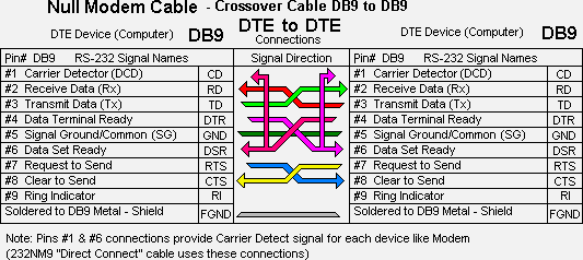
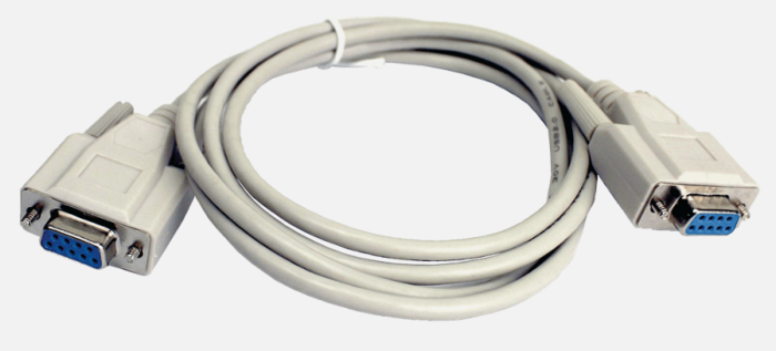
793.5 RS-232 Connectors
DB9 Connector Pinout:
  5  4  3  2  1
   9  8  7  6

Pin 2: RX (Receive Data)
Pin 3: TX (Transmit Data)
Pin 5: GND (Ground)
Common signals:
| Pin | Signal | Direction | Purpose |
|---|---|---|---|
| 1 | DCD | Input | Data Carrier Detect |
| 2 | RX | Input | Receive Data |
| 3 | TX | Output | Transmit Data |
| 4 | DTR | Output | Data Terminal Ready |
| 5 | GND | - | Signal Ground |
| 6 | DSR | Input | Data Set Ready |
| 7 | RTS | Output | Request To Send |
| 8 | CTS | Input | Clear To Send |
| 9 | RI | Input | Ring Indicator |
Minimum connection: TX, RX, GND (3 wires)
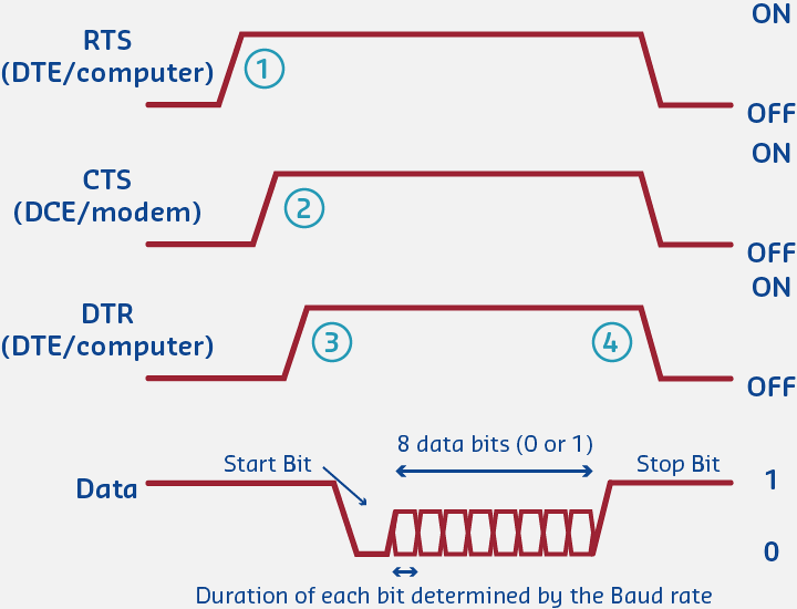
793.6 Data Frame Structure
Start  Data Bits (5-9)      Parity  Stop
 Bit   D0 D1 D2 D3 D4 D5 D6 D7  Bit   Bit(s)
  |    <- Transmitted LSB first ->  |     |
 [0] [1][0][1][1][0][0][1][0]   [0]   [1]

Idle: High (Mark = 1)
Frame components:
- Start bit: 0 (space) - signals beginning of byte
- Data bits: 5-9 bits (usually 8), LSB first
- Parity bit: Optional error checking (even, odd, or none)
- Stop bit(s): 1 or 2 bits (mark = 1) - signals end of byte
Common configurations:
- 8N1: 8 data bits, No parity, 1 stop bit (most common)
- 8E1: 8 data bits, Even parity, 1 stop bit
- 7E1: 7 data bits, Even parity, 1 stop bit (legacy)
793.7 Baud Rate
Baud rate = Speed of communication in bits per second
Common baud rates:
- 9600 bps (common for low-speed sensors)
- 115200 bps (common for debugging, GPS modules)
Both devices must use the SAME baud rate!
793.8 Arduino/ESP32 Example
// UART Serial Communication Example

void setup() {
  // Initialize Serial (USB UART)
  Serial.begin(115200);

  // Initialize Serial2 (Hardware UART on ESP32)
  // RX = GPIO 16, TX = GPIO 17
  Serial2.begin(9600, SERIAL_8N1, 16, 17);

  Serial.println("UART Communication Ready");
}

void loop() {
  // Send data to Serial2
  Serial2.println("Hello from ESP32!");

  // Check if data available from Serial2
  if (Serial2.available()) {
    String received = Serial2.readStringUntil('\n');
    Serial.print("Received: ");
    Serial.println(received);
  }

  delay(1000);
}
Wiring:
ESP32 TX (GPIO 17) -> Device RX
ESP32 RX (GPIO 16) -> Device TX
ESP32 GND          -> Device GND
Common use cases:
- GPS module communication
- Bluetooth module (HC-05/HC-06)
- Serial debugging
- Industrial sensor protocols (Modbus RTU)
Choosing Baud Rate:
- GPS modules: 9600 bps (NMEA standard)
- Debug console: 115200 bps (fast enough, widely compatible)
- Bluetooth modules: 38400 bps (HC-05/HC-06 default)
- Industrial sensors: 19200 bps (Modbus RTU common)
Common Errors:
- Garbled data: Baud rate mismatch (check both TX and RX)
- Works at 9600, fails at 115200: Crystal accuracy issue (use +/-0.5% or better)
- Intermittent errors: Voltage level mismatch (3.3V to 5V needs level shifter)
Optimization:
- Use 8N1 for maximum efficiency (80% vs 72% for 8E1)
- Higher baud rates = lower latency but need better crystal accuracy
- Cable length limits speed: <15m @ 115200 bps, longer cables need lower rates
793.9 Knowledge Check: UART Clock Accuracy
Scenario: A UART connection works correctly at 9600 baud but fails completely at 115200 baud with garbled data. Both devices use 8N1 configuration.
Think about:
- Why would higher baud rates fail when lower baud rates work?
- What is the relationship between clock accuracy and bit timing?
Key Insight: UART is asynchronous (no clock signal), so TX and RX must independently time each bit using their internal clocks.
The Math:
- At 9600 baud (104 us/bit), 2% clock mismatch = 2 us error accumulates to 20 us over 10 bits (start + 8 data + stop) = still within tolerance
- At 115200 baud (8.68 us/bit), 2% error = 0.17 us/bit -> 1.7 us total, exceeding the +/-5% UART tolerance, causing the receiver to sample at wrong times (bit slippage)
Solution: Use precision crystals (<+/-0.5%) or internal RC oscillators with calibration. This is why UART has standardized baud rates (9600, 115200, etc.) - to match common crystal frequencies (16 MHz, 8 MHz).
Scenario: An ESP32 communicates with an Arduino via UART at 115200 baud. The ESP32 runs at 3.3V logic, Arduino at 5V. Direct connection works sometimes but has intermittent errors.
Think about:
- What happens when a 3.3V signal is sent to a 5V input?
- What happens when a 5V signal is sent to a 3.3V input?
Key Insight: The problem is voltage level incompatibility.
- ESP32 TX outputs 3.3V HIGH, but Arduino (5V ATmega328P) requires >=3.5V (typically 0.7 x VCC) to reliably register as HIGH
- At 3.3V, the input is in the undefined region (2V-3.5V), causing intermittent errors
Solution:
- Use bi-directional level shifter (TXS0108E) for safe conversion
- Voltage divider (2k + 1k ohm) on Arduino TX -> ESP32 RX to drop 5V to 3.3V
Direction matters: ESP32->Arduino might work without protection, but Arduino->ESP32 can damage the ESP32’s 3.3V-only input. Never directly connect 5V TX to 3.3V RX without protection.
793.10 Quiz: UART and RS-232
793.11 Summary
This chapter covered UART and RS-232 serial communication:
- RS-232 is a legacy point-to-point protocol using inverted voltage levels (+/-3V to +/-25V)
- UART is the modern TTL-level implementation (0V/3.3V or 0V/5V)
- Data frames consist of start bit, data bits (usually 8), optional parity, and stop bit(s)
- 8N1 (8 data bits, No parity, 1 stop bit) is the most common configuration
- Baud rate must match between sender and receiver
- Common issues include baud rate mismatch, clock accuracy at high speeds, and voltage level incompatibility
793.12 What’s Next
Continue learning about wired protocols:
- I2C Protocol: Two-wire bus for connecting multiple sensors and displays
- SPI Protocol: High-speed interface for SD cards and fast peripherals
- Wired Communication Overview: Return to the overview page