%%{init: {'theme': 'base', 'themeVariables': { 'primaryColor': '#2C3E50', 'primaryTextColor': '#fff', 'primaryBorderColor': '#16A085', 'lineColor': '#16A085', 'secondaryColor': '#E67E22'}}}%%
graph LR
    M["Master"]
    S1["Slave 1<br/>0x3C"]
    S2["Slave 2<br/>0x76"]
    VCC["VCC +3.3V"]
    R1["4.7k"]
    R2["4.7k"]

    VCC --> R1
    VCC --> R2
    R1 -.->|"Pull-up"| SDA
    R2 -.->|"Pull-up"| SCL

    M ---|"SDA (Data)"| SDA[" "]
    M ---|"SCL (Clock)"| SCL[" "]
    SDA --- S1
    SCL --- S1
    SDA --- S2
    SCL --- S2

    style M fill:#2C3E50,stroke:#16A085,color:#fff
    style S1 fill:#16A085,stroke:#16A085,color:#fff
    style S2 fill:#16A085,stroke:#16A085,color:#fff
    style VCC fill:#E67E22,stroke:#16A085,color:#fff
    style R1 fill:#7F8C8D,stroke:#16A085,color:#fff
    style R2 fill:#7F8C8D,stroke:#16A085,color:#fff
794 I2C: Inter-Integrated Circuit Protocol
794.1 Learning Objectives
By the end of this section, you will be able to:
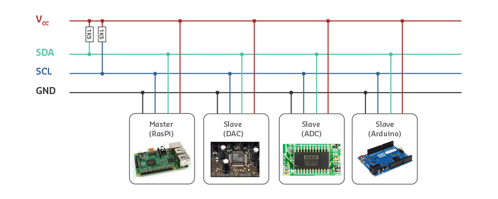
- Understand I2C Architecture: Explain the two-wire bus structure with SDA and SCL
- Configure Pull-Up Resistors: Select appropriate resistor values for reliable communication
- Address I2C Devices: Use 7-bit addressing to communicate with specific devices
- Read and Write Data: Implement I2C read and write transactions
- Debug I2C Issues: Troubleshoot address conflicts, missing pull-ups, and clock stretching
- Write I2C Code: Program Arduino/ESP32 to communicate with sensors and displays
794.2 Prerequisites
Before diving into this chapter, you should be familiar with:
- Wired Communication Fundamentals: Understanding of synchronous communication, multi-drop topology, master-slave architecture
- Digital Electronics: Understanding of open-drain outputs and pull-up resistors
794.3 I2C Overview
I2C (I2C, I-squared-C) is a popular multi-device communication bus developed by Philips (now NXP) in the 1980s.
Pronunciation: “I-squared-C” or “I-two-C”
Full name: Inter-Integrated Circuit
794.3.1 Characteristics
| Feature | Value |
|---|---|
| Wires | 2 only (SDA + SCL) |
| Topology | Multi-drop (bus) |
| Sync/Async | Synchronous (SCL = clock) |
| Duplex | Half-duplex (SDA is bidirectional) |
| Speed | 100 kHz (standard), 400 kHz (fast), 1 MHz (fast+), 3.4 MHz (high-speed) |
| Distance | <1 meter (same PCB or short cable) |
| Devices | Up to 112 (7-bit addressing) or 1024 (10-bit) |
| Master/Slave | Multi-master capable |
794.4 Why I2C is Popular
Advantages:
- Only 2 wires (minimal pin usage)
- Multiple devices on same bus
- Simple addressing (each device has unique address)
- Bidirectional (master can read/write to slaves)
- Well-supported by sensors, displays, EEPROMs
794.5 I2C Signals
SDA (Serial Data):
- Bidirectional data line
- Carries address and data
- Open-drain (requires pull-up resistor)
SCL (Serial Clock):
- Clock signal from master
- Slaves can hold it LOW (“clock stretching”) to slow master
- Open-drain (requires pull-up resistor)
794.6 Pull-Up Resistors
Critical requirement: Both SDA and SCL need pull-up resistors to VCC.
Typical values:
- 4.7 kohm - Most common
- 10 kohm - For slower speeds, longer cables
- 2.2 kohm - For faster speeds, more devices
Why needed? I2C uses open-drain outputs - can only pull LOW, not HIGH. Pull-up resistors provide the HIGH level.

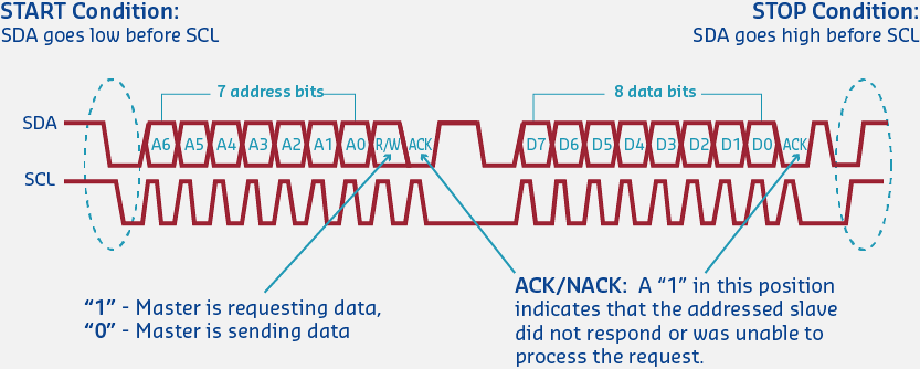
794.7 I2C Addressing
Each device on the bus needs a unique 7-bit address.
Address space:
- 7-bit addresses: 0x08 to 0x77 (112 addresses)
- Some addresses reserved (0x00-0x07, 0x78-0x7F)
Common I2C device addresses:
| Device | Address (Hex) | Address (Decimal) |
|---|---|---|
| OLED Display (SSD1306) | 0x3C or 0x3D | 60 or 61 |
| BME280 (Temp/Humidity) | 0x76 or 0x77 | 118 or 119 |
| MPU6050 (IMU) | 0x68 or 0x69 | 104 or 105 |
| RTC DS3231 | 0x68 | 104 |
| EEPROM 24C256 | 0x50 - 0x57 | 80 - 87 |
Finding device addresses:
// I2C Scanner
#include <Wire.h>

void setup() {
  Serial.begin(115200);
  Wire.begin();
  Serial.println("I2C Scanner");

  for (byte addr = 1; addr < 127; addr++) {
    Wire.beginTransmission(addr);
    if (Wire.endTransmission() == 0) {
      Serial.print("Device found at 0x");
      if (addr < 16) Serial.print("0");
      Serial.println(addr, HEX);
    }
  }
  Serial.println("Scan complete");
}

void loop() {}
794.8 I2C Communication Protocol

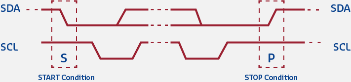
Start and Stop Conditions:
     SDA  ____        ________________        ____
              \_______/                \______/

     SCL  _________                ____________
                   \_______/\_____/

          <-START-> <-DATA-> <-STOP->
START: SDA goes HIGH->LOW while SCL is HIGH
STOP: SDA goes LOW->HIGH while SCL is HIGH
Data Transfer (1 byte + ACK):
Bit:  7   6   5   4   3   2   1   0  ACK
     ___     ___         ___     ___ ___
SDA:    \___/   \_______/   \___/      (Data bits + ACK)

     _   _   _   _   _   _   _   _   _
SCL: _|_|_|_|_|_|_|_|_|_|_|_|_|_|_|_|_ (Clock pulses)

     <--------- 8 Data Bits -------> <A>
                                      |
                                     ACK (0=success, 1=fail)
Data transfer rules:
- SDA can only change when SCL is LOW
- SDA is sampled when SCL is HIGH
- Data transmitted MSB first (most significant bit first)
794.9 I2C Write Transaction
%%{init: {'theme': 'base', 'themeVariables': { 'primaryColor': '#2C3E50', 'primaryTextColor': '#fff', 'primaryBorderColor': '#16A085', 'lineColor': '#16A085', 'secondaryColor': '#E67E22'}}}%%
sequenceDiagram
    participant M as Master
    participant S as Slave (0x68)

    M->>S: START
    M->>S: Address (0x68) + W (0)
    S->>M: ACK
    M->>S: Register Address (0x6B)
    S->>M: ACK
    M->>S: Data Byte (0x00)
    S->>M: ACK
    M->>S: STOP

    Note over M,S: Write Complete
Steps:
- Master sends START
- Master sends slave address + write bit (0)
- Slave acknowledges (ACK)
- Master sends register address
- Slave ACKs
- Master sends data byte
- Slave ACKs
- Master sends STOP
794.10 I2C Read Transaction
%%{init: {'theme': 'base', 'themeVariables': { 'primaryColor': '#2C3E50', 'primaryTextColor': '#fff', 'primaryBorderColor': '#16A085', 'lineColor': '#16A085', 'secondaryColor': '#E67E22'}}}%%
sequenceDiagram
    participant M as Master
    participant S as Slave (0x68)

    M->>S: START
    M->>S: Address (0x68) + W (0)
    S->>M: ACK
    M->>S: Register Address (0x3B)
    S->>M: ACK
    M->>S: RESTART
    M->>S: Address (0x68) + R (1)
    S->>M: ACK
    S->>M: Data Byte 1
    M->>S: ACK
    S->>M: Data Byte 2
    M->>S: NACK (finished)
    M->>S: STOP

    Note over M,S: Read Complete
794.11 Arduino/ESP32 I2C Example
#include <Wire.h>

// I2C device address
#define MPU6050_ADDR 0x68

void setup() {
  Serial.begin(115200);
  Wire.begin();  // Initialize I2C

  // Wake up MPU6050 (write 0 to PWR_MGMT_1 register)
  Wire.beginTransmission(MPU6050_ADDR);
  Wire.write(0x6B);  // Register address
  Wire.write(0);     // Wake up
  Wire.endTransmission(true);

  Serial.println("MPU6050 Initialized");
}

void loop() {
  // Read accelerometer X-axis (registers 0x3B-0x3C)
  Wire.beginTransmission(MPU6050_ADDR);
  Wire.write(0x3B);  // Starting register
  Wire.endTransmission(false);  // Repeated start

  Wire.requestFrom(MPU6050_ADDR, 2, true);  // Request 2 bytes

  if (Wire.available() >= 2) {
    int16_t accelX = Wire.read() << 8 | Wire.read();

    Serial.print("Accel X: ");
    Serial.println(accelX);
  }

  delay(500);
}
Wiring (ESP32):
ESP32 GPIO 21 (SDA) -> Sensor SDA
ESP32 GPIO 22 (SCL) -> Sensor SCL
ESP32 3.3V          -> Sensor VCC
ESP32 GND           -> Sensor GND

(Add 4.7k pull-up resistors on SDA and SCL if not on sensor board)
794.12 Clock Stretching
Problem: Slave needs more time to process data.
Solution: Slave holds SCL LOW to pause communication.
Master releases SCL (expects HIGH)
Slave holds SCL LOW (clock stretching)
Master waits...
Slave releases SCL (ready to continue)
Communication resumes
Use case: Slow sensors (temperature readings take time), EEPROM write operations.
TipPractical Tips
Avoiding Address Conflicts:
- Check device datasheets before buying
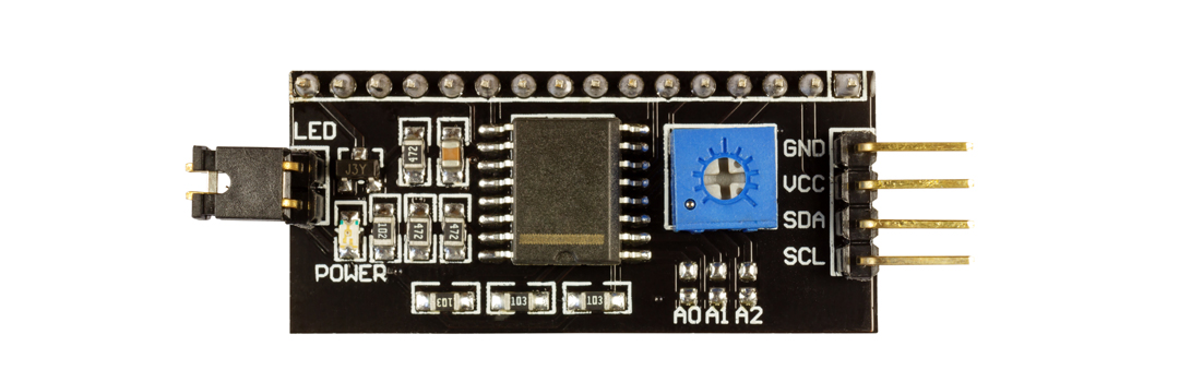
- Many sensors have address select pins (A0, AD0) to change address
- Use I2C scanner sketch to verify addresses
- Plan device selection to avoid conflicts
Common Conflicts:
- 0x68: MPU6050, DS1307/DS3231 RTC -> Use MPU6050 AD0 pin for 0x69
- 0x76/0x77: BMP280, BME280, BME680 -> Use SDO pin
- 0x27/0x3F: LCD backpack modules -> Check board
Pull-up Resistors:
- 4.7k: Most common (400 kHz)
- 2.2k: Long cables or many devices
- 10k: Short cables, few devices
794.13 Hands-On Lab: I2C Scanner
Objective: Find all I2C devices connected to your ESP32/Arduino.
#include <Wire.h>

void setup() {
  Serial.begin(115200);
  Wire.begin();

  Serial.println("\nI2C Scanner");
  Serial.println("Scanning for devices...\n");

  byte count = 0;

  for (byte i = 8; i < 120; i++) {
    Wire.beginTransmission(i);
    if (Wire.endTransmission() == 0) {
      Serial.print("Found device at address: 0x");
      if (i < 16) Serial.print("0");
      Serial.print(i, HEX);
      Serial.print(" (");
      Serial.print(i);
      Serial.println(")");
      count++;
    }
  }

  Serial.print("\nTotal devices found: ");
  Serial.println(count);
}

void loop() {}
Expected output:
I2C Scanner
Scanning for devices...

Found device at address: 0x3C (60)
Found device at address: 0x76 (118)

Total devices found: 2
794.14 Hands-On Lab: BME280 Temperature Sensor
Objective: Read temperature from BME280 sensor via I2C.
#include <Wire.h>
#include <Adafruit_BME280.h>

Adafruit_BME280 bme;  // I2C

void setup() {
  Serial.begin(115200);

  if (!bme.begin(0x76)) {  // I2C address
    Serial.println("BME280 sensor not found!");
    while (1);  // Halt
  }

  Serial.println("BME280 Ready");
}

void loop() {
  float temperature = bme.readTemperature();
  float humidity = bme.readHumidity();
  float pressure = bme.readPressure() / 100.0F;

  Serial.print("Temp: ");
  Serial.print(temperature);
  Serial.print(" C, Humidity: ");
  Serial.print(humidity);
  Serial.print(" %, Pressure: ");
  Serial.print(pressure);
  Serial.println(" hPa");

  delay(2000);
}
794.15 Knowledge Check: I2C Multi-Master Arbitration
TipUnderstanding Check: I2C Multi-Master Arbitration
Scenario: You’re designing a robotics platform with two microcontrollers (ESP32 and Arduino) that both need to control a shared OLED display (I2C address 0x3C) and BME280 sensor (0x76). Both MCUs operate as I2C masters on the same bus with 4.7k pull-ups.
Think about:
- What happens if both masters try to send a START condition simultaneously?
- Why doesn’t this cause electrical damage to the devices?
Key Insight: I2C uses wired-AND arbitration through open-drain outputs. When multiple masters transmit simultaneously, any device pulling SDA LOW wins (LOW overrides HIGH). During arbitration, masters compare transmitted bits to actual bus state:
- Master transmits 1 (releases line HIGH)
- Bus reads 0 (another master pulled LOW)
- First master detects mismatch -> backs off gracefully
- No electrical conflict because open-drain outputs never drive HIGH (only pull LOW or float)
This elegant mechanism prevents bus damage. Push-pull outputs (like SPI) would short VCC to GND if two devices drive opposite levels, potentially destroying the chips. The trade-off: RC charging through pull-up resistors limits rise time, restricting I2C to ~400 kHz vs SPI’s 80+ MHz.
Verify Your Understanding:
- Calculate arbitration delay: With 400 pF bus capacitance and 4.7k pull-ups, rise time = 2.2 x 4700 ohm x 400pF = 4.1 us. This limits maximum clock frequency to ~200 kHz for reliable multi-master operation.
- Why faster rise times require smaller pull-ups: At 100 kHz (standard mode), 10k resistors work. At 400 kHz (fast mode), 2.2k needed for adequate rise time.
794.16 Quiz: I2C Protocol

794.17 Summary
This chapter covered I2C (Inter-Integrated Circuit) protocol:
- Two-wire bus (SDA for data, SCL for clock) supports multiple devices
- Open-drain outputs with pull-up resistors (typically 4.7k) enable multi-master operation
- 7-bit addressing allows up to 112 devices on a single bus
- Synchronous protocol with master-controlled clock and optional clock stretching
- Half-duplex communication with START, STOP, and ACK/NACK conditions
- Common devices: Temperature sensors (BME280), displays (SSD1306), IMUs (MPU6050), RTCs (DS3231)
794.18 What’s Next
Continue learning about wired protocols:
- SPI Protocol: High-speed full-duplex interface for SD cards and fast peripherals
- UART and RS-232: Serial point-to-point communication
- Wired Communication Overview: Return to the overview page