%%{init: {'theme': 'base', 'themeVariables': { 'primaryColor': '#2C3E50', 'primaryTextColor': '#fff', 'primaryBorderColor': '#16A085', 'lineColor': '#16A085', 'fontSize': '12px'}}}%%
graph LR
subgraph ESP32["ESP32 DevKit V1"]
G2[GPIO 2]
G4[GPIO 4]
G5[GPIO 5]
G18[GPIO 18]
G19[GPIO 19]
G15[GPIO 15]
G16[GPIO 16]
G17[GPIO 17]
G21[GPIO 21]
GND[GND]
end
subgraph LEDs["Status LEDs"]
GL[Green LED<br/>Boot Success]
RL[Red LED<br/>Boot Failure]
YL[Yellow LED<br/>Verifying]
BL[Blue LED<br/>Key Ops]
WL[White LED<br/>Rollback]
end
subgraph Buttons["Control Buttons"]
B1[Button 1<br/>Normal Boot]
B2[Button 2<br/>Tamper Attack]
B3[Button 3<br/>Rollback Attack]
B4[Button 4<br/>Reset]
end
G2 --> GL
G4 --> RL
G5 --> YL
G18 --> BL
G19 --> WL
G15 --> B1
G16 --> B2
G17 --> B3
G21 --> B4
B1 --> GND
B2 --> GND
B3 --> GND
B4 --> GND
style ESP32 fill:#2C3E50,stroke:#16A085,color:#fff
style LEDs fill:#f8f9fa,stroke:#16A085
style Buttons fill:#f8f9fa,stroke:#E67E22
1471 Firmware Security and Secure Updates
1471.1 Learning Objectives
By the end of this chapter, you will be able to:
- Design Secure Boot Chains: Implement hardware root of trust with verified bootloader, kernel, and application stages
- Implement Code Signing: Use cryptographic signatures to verify firmware authenticity before installation
- Deploy Anti-Rollback Protection: Prevent downgrade attacks using OTP fuse-based version counters
- Build Resilient OTA Systems: Design over-the-air update mechanisms with automatic rollback on failure
- Apply Defense in Depth: Combine encryption, signing, and verification for comprehensive firmware protection
TipFor Beginners: Firmware Security
What is Firmware Security? Firmware is the permanent software programmed into IoT devices—the code that runs when devices boot up. Firmware security ensures that only authentic, unmodified code executes on devices. This includes secure boot (verifying code before running), code signing (cryptographically proving authenticity), and secure updates (safely delivering new firmware over-the-air).
Why does it matter? Attackers who can install malicious firmware gain complete control over devices. They can steal data, manipulate sensors, join botnets, or even cause physical damage. Secure firmware prevents these attacks by ensuring devices only run code from trusted sources.
Key terms: | Term | Definition | |——|————| | Secure Boot | Verification chain ensuring only signed firmware executes, starting from hardware root of trust | | Code Signing | Cryptographically signing firmware with private key so devices can verify authenticity with public key | | OTA Update | Over-The-Air firmware update delivered via network without physical access | | Anti-Rollback | Prevention of downgrade attacks using version counters in OTP (One-Time Programmable) memory | | Root of Trust | Immutable hardware component (Boot ROM) that cannot be modified and starts the verification chain |
1471.2 Prerequisites
Before diving into this chapter, you should be familiar with:
- Encryption Principles: Understanding of digital signatures, hashing, and key management
- Authentication and Credentials: Certificate chains and identity verification
- Software Vulnerabilities: Attack vectors that firmware security prevents
1471.3 Secure Boot Chain Design
NoteAcademic Resource: Code-Signing Process
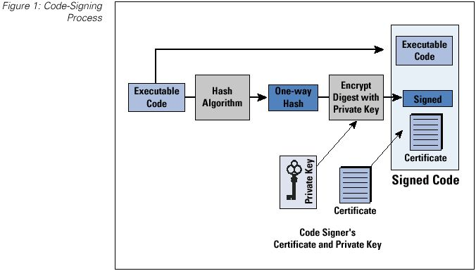
Source: University of Edinburgh IoT Security Course - This diagram shows the complete code-signing workflow used to secure IoT firmware updates, ensuring only authenticated and unmodified code is installed on devices.
1471.4 Worked Example: Implementing Secure Boot Chain for Smart Meter
Scenario: A utility company deploys 100,000 smart electricity meters across a metropolitan area. After discovering that attackers could flash malicious firmware to manipulate energy readings (causing billing fraud and grid instability), the company must implement a secure boot chain to ensure only authenticated firmware runs on deployed meters.
Given: - 100,000 smart meters deployed in field (cannot be physically recalled) - Current state: Firmware updates via unencrypted HTTP, no signature verification - Meters have ARM Cortex-M4 MCU with 256KB flash, 64KB RAM - Hardware constraint: No dedicated HSM, but MCU has hardware AES and SHA-256 acceleration - Attack vector: Attacker with physical access can connect JTAG and flash arbitrary firmware - Requirement: Prevent unauthorized firmware from executing, even with physical access
Steps:
Design the boot chain hierarchy:
SECURE BOOT CHAIN (Root of Trust to Application):

+------------------+
| Boot ROM (8KB)   | <-- Immutable, burned into silicon at factory
| - Contains:      |     - Cannot be modified by software or JTAG
|   Public key hash|     - First code to execute after power-on
|   SHA-256 verify |
+--------+---------+
         |
         | Verifies signature of:
         v
+------------------+
| Bootloader (16KB)| <-- Stored in protected flash region
| - Contains:      |     - Can be updated (signed updates only)
|   Manufacturer   |
|   public key     |
|   Update logic   |
+--------+---------+
         |
         | Verifies signature of:
         v
+------------------+
| Application FW   | <-- Main meter firmware (200KB)
| - Meter logic    |     - Regular updates for features/security
| - Comms stack    |
| - Crypto libs    |
+------------------+
Implement firmware signing at build time:
BUILD PIPELINE (at manufacturer):

Source Code --> Compiler --> firmware.bin (unsigned)
                                  |
                                  v
+--------------------------------------------------+
| SIGNING PROCESS (HSM-protected, air-gapped)      |
|                                                  |
| 1. Calculate SHA-256 hash of firmware.bin       |
|    hash = SHA256(firmware.bin)                  |
|    = "a3f2b8c1d4e5..."                         |
|                                                  |
| 2. Sign hash with Ed25519 private key (in HSM)  |
|    signature = Ed25519_Sign(private_key, hash)  |
|    = "7b8a9c0d1e2f..." (64 bytes)              |
|                                                  |
| 3. Create signed firmware package               |
|    firmware_signed.bin = {                      |
|      magic: "SMFW"                              |
|      version: 2.3.1                             |
|      timestamp: 2026-01-11T10:30:00Z            |
|      firmware_size: 204,800                     |
|      signature: "7b8a9c0d1e2f..."              |
|      firmware_data: [binary]                    |
|    }                                            |
+--------------------------------------------------+
Implement anti-rollback protection:
ANTI-ROLLBACK MECHANISM:

Problem: Attacker flashes old firmware with known vulnerabilities

Solution: Monotonic counter in OTP (one-time programmable) memory

OTP Fuse Bank (can only be incremented, never decremented):
+---+---+---+---+---+---+---+---+
| 1 | 1 | 1 | 1 | 1 | 0 | 0 | 0 |  = Version 5
+---+---+---+---+---+---+---+---+

Firmware header contains: minimum_version = 5

Boot verification:
1. Read OTP counter value: current_version = 5
2. Read firmware minimum_version from header: 5
3. If firmware.min_version < current_version: REJECT (rollback attempt)
4. If firmware.version > current_version: Burn additional fuse bits
5. Proceed with signature verification

Result: Once version 5 boots successfully, versions 1-4 can NEVER boot again
Handle secure recovery for bricked devices: | Failure Scenario | Recovery Action | Security Consideration | |——————|—————–|————————| | Signature verification fails | Enter recovery mode, wait for signed recovery image | Recovery image also requires valid signature | | OTP counter mismatch | Reject boot, require factory service | Prevents rollback even in recovery | | Flash corruption | Boot to recovery partition | Recovery partition is read-only, signed | | Update interrupted | Dual-bank: Boot from previous partition | A/B partitioning ensures always-bootable |
Result: - Chain of trust from hardware root (Boot ROM) to application firmware - Every boot verifies firmware signature before execution - Physical access (JTAG) cannot bypass signature verification (Boot ROM is immutable) - Anti-rollback prevents downgrade attacks to vulnerable versions - Dual-bank update ensures meters remain operational even if update fails
Key Insight: Secure boot is only as strong as its root of trust. The Boot ROM must be immutable (burned into silicon) and contain the verification logic and public key hash. Everything above the Boot ROM can be updated, but only if signed by the trusted key.
1471.5 Tradeoffs in Secure Boot Design
WarningTradeoff: Full Secure Boot vs Verified Boot
Option A: Full secure boot with hardware root of trust (Boot ROM verification, TPM/secure enclave, fused keys) Option B: Verified boot with software-only signature checking (bootloader verifies firmware signature without hardware backing) Decision Factors: Choose full secure boot for high-security applications (medical devices, industrial controllers, vehicles, payment terminals) where physical attacks are a concern and compliance requires hardware-backed security. Choose verified boot for cost-sensitive consumer IoT where software verification provides sufficient protection against remote attacks. Full secure boot adds $2-10 per device in hardware costs (secure element, TPM) but prevents key extraction via side-channel attacks and provides tamper evidence. Verified boot can be bypassed by attackers with physical access who can modify the bootloader itself.
WarningTradeoff: Aggressive Anti-Rollback vs Rollback Flexibility
Option A: Strict anti-rollback policy using OTP fuses that permanently block all previous firmware versions Option B: Flexible rollback allowing reversion to previous N versions with time-limited validity windows Decision Factors: Choose strict anti-rollback for security-critical devices (pacemakers, vehicle ECUs, industrial safety systems) where running vulnerable firmware poses unacceptable risk. Choose flexible rollback for consumer devices and development environments where a bad update might brick devices and user experience matters more than preventing sophisticated downgrade attacks. Strict anti-rollback cannot be undone (OTP fuses are permanent), so a single bad firmware release can brick entire device fleets. Flexible rollback reduces bricking risk but allows attackers to exploit known vulnerabilities by downgrading firmware. Consider hybrid approaches: strict anti-rollback for security patches, flexible rollback for feature updates.
1471.6 Worked Example: Implementing Automatic Rollback for Smart Lock
Scenario: A smart lock manufacturer deploys 80,000 Bluetooth-enabled door locks in residential buildings. After a firmware update (v3.2.0) introduced a bug causing 2.3% of locks to fail Bluetooth pairing after reboot, customers were locked out of their homes. The company must implement automatic rollback to prevent future incidents.
Given: - Fleet size: 80,000 smart locks (ESP32-based, 4MB flash) - Firmware size: 1.2 MB per partition - Flash layout: Bootloader (64KB) + Partition A (1.5MB) + Partition B (1.5MB) + NVS (64KB) - Boot failure rate threshold: 0.5% (400 devices) - Average boot time: 3.2 seconds - Watchdog timeout: 30 seconds - Health check duration: 10 seconds post-boot
Steps:
Design boot counter and health check mechanism:
- Boot counter stored in NVS (non-volatile storage)
- Counter increments on every boot attempt
- Counter resets to 0 only after successful health check
- Maximum boot attempts before rollback: 3
Define health check criteria:
- Bluetooth stack initialization: PASS/FAIL (critical)
- Motor driver response: PASS/FAIL (critical)
- NFC reader initialization: PASS/FAIL (non-critical)
- Wi-Fi association (if configured): PASS/FAIL (non-critical)
- Health check pass: All critical checks pass within 10 seconds
Calculate failure detection time:
- Boot attempt 1: 3.2s boot + 10s health check = 13.2s (fail)
- Boot attempt 2: 3.2s boot + 10s health check = 13.2s (fail)
- Boot attempt 3: 3.2s boot + 10s health check = 13.2s (fail, trigger rollback)
- Rollback boot: 3.2s boot + 10s health check = 13.2s (pass)
- Maximum time to recovery: 52.8 seconds
Implement rollback state machine:
State transitions:
BOOT_NEW -> (health_pass) -> COMMIT_NEW
BOOT_NEW -> (health_fail && attempts < 3) -> RETRY_NEW
RETRY_NEW -> (health_pass) -> COMMIT_NEW
RETRY_NEW -> (health_fail && attempts >= 3) -> ROLLBACK
ROLLBACK -> (switch to partition A) -> BOOT_OLD
BOOT_OLD -> (health_pass) -> SAFE_MODE
SAFE_MODE -> (report to cloud) -> AWAIT_FIX
Calculate fleet-wide rollback impact:
- v3.2.0 failure rate: 2.3% = 1,840 devices
- With automatic rollback: 1,840 devices recover in <60 seconds
- Without rollback: 1,840 customers locked out (support tickets, locksmith calls)
- Support cost avoided: 1,840 x $150 average incident cost = $276,000
Result: The automatic rollback mechanism detects Bluetooth pairing failures within 3 boot attempts (52.8 seconds worst case) and reverts to the previous known-good firmware. The 2.3% of affected devices (1,840 locks) automatically recover without customer intervention.
Key Insight: Automatic rollback is about time to recovery, not just failure detection. A 3-attempt limit with 10-second health checks provides enough retry margin for transient failures while ensuring genuine firmware bugs trigger rollback within one minute.
1471.7 Worked Example: Signature Verification Chain for Medical Device
Scenario: A medical device manufacturer produces 12,000 insulin pumps that receive firmware updates via Bluetooth from a companion smartphone app. FDA regulations (21 CFR Part 11, IEC 62443) require cryptographic verification of all software updates.
Given: - Fleet size: 12,000 insulin pumps (ARM Cortex-M4, 256KB flash, 64KB RAM) - Firmware update size: 180 KB - Bluetooth transfer rate: 125 Kbps (BLE 4.2) - CPU clock: 64 MHz - Cryptographic library: mbedTLS (optimized for embedded) - Regulatory: FDA Class II, IEC 62443 SL2 - Threat model: Malicious app, compromised smartphone, supply chain attack
Steps:
Design three-level certificate hierarchy:
Root CA (HSM-protected, offline)
  +-- Intermediate CA (Code Signing)
       +-- Firmware Signing Key (per-product)

Key algorithms:
- Root CA: Ed25519 (256-bit, fast verification)
- Intermediate: Ed25519
- Firmware key: Ed25519

Certificate lifetimes:
- Root: 20 years (never rotated)
- Intermediate: 5 years (rotated with firmware)
- Firmware: 2 years (per-version)
Calculate signature verification time:
- Ed25519 verification on Cortex-M4 @ 64MHz: ~12 ms
- Three signatures to verify: Root, Intermediate, Firmware
- Hash calculation (SHA-256, 180KB): ~45 ms
- Total verification time: 3 x 12ms + 45ms = 81 ms
Design update package structure:
SIGNED_PACKAGE (196 KB total):
+------------------------------------------+
| Header (256 bytes)                       |
|   - Magic: 0x494E5355 ("INSU")           |
|   - Version: 4.2.1                        |
|   - Target HW: PM-300                     |
|   - Min version: 4.0.0 (anti-rollback)   |
|   - Firmware size: 180,224 bytes          |
|   - SHA-256 hash: [32 bytes]              |
+------------------------------------------+
| Certificate chain (2 KB)                 |
|   - Intermediate cert: 512 bytes          |
|   - Firmware cert: 512 bytes              |
|   - Signatures: 64 + 64 bytes             |
+------------------------------------------+
| Firmware image (180 KB)                  |
|   - Encrypted with AES-256-GCM            |
|   - IV: [12 bytes]                        |
|   - Auth tag: [16 bytes]                  |
+------------------------------------------+
| Package signature (64 bytes)             |
+------------------------------------------+
Implement verification sequence:
- Step 1: Verify package signature against firmware cert (12 ms)
- Step 2: Verify firmware cert against intermediate cert (12 ms)
- Step 3: Verify intermediate cert against root CA (embedded) (12 ms)
- Step 4: Calculate SHA-256 hash of firmware image (45 ms)
- Step 5: Compare hash with signed header value (0.1 ms)
- Step 6: Check version >= min_version (anti-rollback) (0.1 ms)
- Step 7: Decrypt firmware with device-specific key (95 ms)
- Total verification: 176 ms (before writing to flash)
Calculate security coverage:
- Attack blocked: Unsigned firmware (signature check fails)
- Attack blocked: Old firmware replay (anti-rollback check)
- Attack blocked: Firmware for different product (target HW check)
- Attack blocked: Tampered firmware (hash mismatch)
- Attack blocked: Stolen signing key (cert expiry + revocation)
- Remaining risk: Compromised HSM (mitigated by HSM security)
Result: The insulin pump verifies firmware authenticity in 176 ms using a three-level certificate chain with Ed25519 signatures. This verification runs entirely on-device before any flash writes occur, ensuring that malicious firmware cannot execute.
Key Insight: Medical device firmware security is about defense in depth with regulatory compliance. The 176 ms verification overhead is negligible compared to the 11.5-second BLE transfer time for a 180 KB update. The critical design choice is using Ed25519 over RSA—at equivalent security levels, Ed25519 verification is 10x faster on resource-constrained MCUs (12 ms vs 120 ms for RSA-2048).
1471.8 Worked Example: Secure OTA Update System for Connected Vehicles
Scenario: An automotive OEM operates a fleet of 50,000 connected vehicles with telematics control units (TCUs) that receive over-the-air firmware updates. The OEM must design a robust, secure OTA update system that ensures integrity, prevents attacks, and guarantees vehicle safety even if updates fail.
Given: - 50,000 vehicles with ARM-based TCUs (1GB flash, 512MB RAM) - Cellular connectivity (4G LTE) with average 10 Mbps bandwidth - Update sizes: 50MB (minor patches) to 500MB (major releases) - Safety requirement: Vehicle must remain drivable even if update fails - Regulatory: UN R155 (cybersecurity), UN R156 (software updates) - Threat model: Nation-state attackers, criminal hackers, insider threats
Key Design Elements:
- Signed Update Package Structure:
- Outer envelope signed by Release Management key
- Manifest with target vehicles, minimum version, install conditions
- Per-component encryption with device-specific keys
- Staged Rollout Strategy:
- Phase 1: Internal testing (100 employee vehicles, 7 days)
- Phase 2: Early adopter (1,000 opt-in customers, 7 days)
- Phase 3: Regional rollout (10,000 vehicles, 14 days)
- Phase 4: Full fleet (remaining 39,000, rolling 10,000/week)
- Automatic pause if rollback rate >0.1% or safety event detected
- Vehicle-Side Update Process:
- Download: Background while driving, resume on interruption
- Verify: Check signatures, version anti-rollback, hash integrity
- Stage: Decrypt and write to inactive partition
- User Consent: Display changelog, schedule installation
- Install: Only when parked, battery >50%, switch boot partition
- Validate: Run self-test, commit or auto-rollback
- A/B Partition Scheme for Atomic Updates:
- Partition A: Currently active system
- Partition B: Staging area for new firmware
- Boot Config Block: Tracks active partition, boot count, status
- Auto-rollback to previous partition if boot fails 3x
Result: - Updates download in background while vehicle is in use - Installation only occurs when vehicle is safely parked - Atomic A/B updates mean the vehicle is ALWAYS bootable - Automatic rollback if new firmware fails to boot 3 times - Staged rollout catches issues before fleet-wide deployment
Key Insight: Vehicle OTA updates have a critical safety dimension. Key principles: (1) Never modify the running system—always stage to inactive partition; (2) Never leave the vehicle unbootable—A/B partitions guarantee this; (3) Automatic rollback is mandatory; (4) Staged rollout is not optional.
1471.9 Visual Reference Gallery
NoteVisual: Secure OTA Update Process

Secure OTA updates ensure firmware integrity through cryptographic signatures, preventing attackers from installing malicious firmware even with network access to devices.
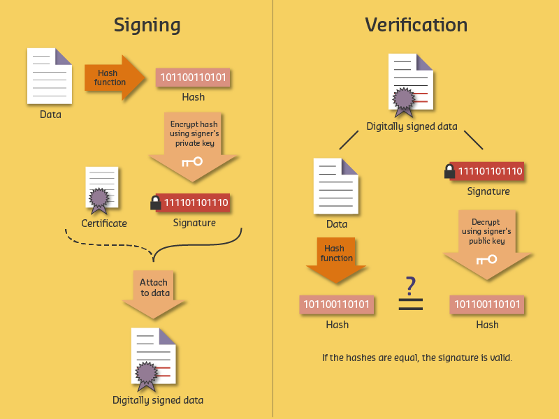
NoteVisual: Code Signing Process

Code signing establishes trust in software authenticity, enabling devices to verify that firmware originates from legitimate sources and has not been modified since signing.
1471.10 Secure Boot Lab: ESP32 Firmware Security Simulation
This hands-on lab provides an interactive simulation of secure boot concepts using an ESP32 microcontroller in the Wokwi simulator. You will explore boot verification, firmware integrity checking, rollback protection, and secure key storage through practical code examples.
NoteWhat You Will Learn
In this lab, you will gain practical experience with:
- Boot Verification Process: Understand how devices verify firmware authenticity before execution
- Firmware Integrity Checking: Implement SHA-256 hash verification to detect tampering
- Rollback Protection: Learn how anti-rollback counters prevent downgrade attacks
- Secure Key Storage: Explore secure storage simulation for cryptographic keys
- Boot State Indicators: Visualize boot states through LED indicators and serial output
- Attack Simulation: See what happens when firmware is tampered with
Prerequisites: Basic Arduino/C++ syntax, understanding of secure boot concepts from this chapter
Estimated Time: 45-60 minutes
1471.10.1 Lab Components
| Component | Purpose | Wokwi Part |
|---|---|---|
| ESP32 DevKit V1 | Main microcontroller simulating secure boot | board-esp32-devkit-c-v4 |
| Green LED | Indicates successful boot/verification | led |
| Red LED | Indicates boot failure/tampering detected | led |
| Yellow LED | Indicates verification in progress | led |
| Blue LED | Indicates secure key operations | led |
| White LED | Indicates rollback protection active | led |
| Push Button 1 | Trigger normal boot sequence | button |
| Push Button 2 | Simulate firmware tampering attack | button |
| Push Button 3 | Simulate rollback attack | button |
| Push Button 4 | Reset boot state | button |
| Resistors (5x 220 ohm) | Current limiting for LEDs | resistor |
1471.10.2 Interactive Wokwi Simulator
Use the embedded simulator below to build and test your secure boot simulation. Wire the circuit as shown, paste the code, and click “Start Simulation”.
TipSimulator Tips
- Wire first: Connect all components before pasting code
- Paste code: Copy the complete code into the editor
- Run: Click the green “Play” button to compile and run
- Serial Monitor: View detailed boot process output in the Serial Monitor panel
- Buttons: Use the on-screen buttons to simulate different boot scenarios
- Save: Create a free Wokwi account to save your projects
1471.10.3 Circuit Connections
Wire the circuit in Wokwi before entering the code:
ESP32 Pin Connections:
----------------------
GPIO 2  --> Green LED (+)  --> 220 ohm Resistor --> GND  (Boot Success)
GPIO 4  --> Red LED (+)    --> 220 ohm Resistor --> GND  (Boot Failure)
GPIO 5  --> Yellow LED (+) --> 220 ohm Resistor --> GND  (Verification)
GPIO 18 --> Blue LED (+)   --> 220 ohm Resistor --> GND  (Key Operations)
GPIO 19 --> White LED (+)  --> 220 ohm Resistor --> GND  (Rollback Protection)
GPIO 15 --> Button 1       --> GND  (Normal Boot)
GPIO 16 --> Button 2       --> GND  (Tamper Attack)
GPIO 17 --> Button 3       --> GND  (Rollback Attack)
GPIO 21 --> Button 4 --> GND (Reset State)1471.10.4 Step-by-Step Lab Instructions
Follow these steps to complete the secure boot lab:
NoteStep 1: Build the Circuit
- Open the Wokwi simulator above
- Add components from the parts panel:
- 1x ESP32 DevKit V1
- 5x LEDs (green, red, yellow, blue, white)
- 5x 220 ohm resistors
- 4x push buttons
- Wire according to the circuit diagram:
- Connect LEDs through resistors to GPIO 2, 4, 5, 18, 19
- Connect buttons to GPIO 15, 16, 17, 21 (other pin to GND)
- Verify all connections before proceeding
NoteStep 2: Execute Normal Boot Sequence
- Press Button 1 (GPIO 15) to trigger a normal boot
- Observe in the Serial Monitor:
- Power-on and ROM initialization
- Bootloader hash computation and verification
- Kernel hash computation and verification
- Application hash and rollback check
- Watch the Yellow LED blink during each verification stage
- When boot completes successfully:
- Green LED turns on (boot success)
- White LED turns on (rollback protection active)
- Note how the anti-rollback counter increments
NoteStep 3: Simulate Firmware Tampering Attack
- Press Button 2 (GPIO 16) to simulate tampering
- The simulation injects “malicious code” into the firmware
- Watch the Serial Monitor show:
- Modified firmware data strings
- Hash computation of tampered data
- HASH MISMATCH detection
- Detailed explanation of why boot was halted
- The Red LED blinks and stays on (boot failure)
- Device refuses to execute untrusted code!
NoteStep 4: Simulate Rollback Attack
- Press Button 4 (GPIO 21) to reset the state first
- Execute a normal boot (Button 1) to update the anti-rollback counter
- Press Button 3 (GPIO 17) to simulate a rollback attack
- The simulation attempts to install “version 1.0.0” (old firmware)
- Observe:
- Rollback protection check FAILS
- Current version (1.0.0) < Minimum required version
- Attack blocked before firmware can execute
- Red LED indicates the attack was prevented
1471.10.5 Expected Outcomes
After completing this lab, you should be able to:
| Outcome | Verification |
|---|---|
| Understand the chain of trust concept | Can explain how ROM verifies bootloader, bootloader verifies kernel, etc. |
| Explain hash-based integrity checking | Can describe how SHA-256 detects any modification to firmware |
| Describe rollback protection | Can explain why anti-rollback counters prevent downgrade attacks |
| Identify secure boot failure modes | Can list at least 3 ways secure boot can fail and what each means |
| Understand boot attempt limiting | Can explain why devices limit boot attempts and enter recovery mode |
| Visualize the secure boot process | Can draw a diagram showing verification flow from ROM to application |
TipKey Security Principles Demonstrated
This lab illustrates these essential secure boot principles:
- Immutable Root of Trust: The ROM code and embedded public key cannot be modified
- Chain of Trust: Each stage verifies the next before transferring control
- Fail-Secure Design: Any verification failure halts the boot process
- Anti-Rollback Protection: Prevents attackers from exploiting old vulnerabilities
- Cryptographic Verification: SHA-256 hashes and digital signatures ensure authenticity
- Defense in Depth: Multiple verification layers protect against different attack vectors
Real-world application: ESP32 devices in production use similar mechanisms with hardware-backed eFuse storage, making keys truly immutable. This simulation helps you understand the concepts before working with production-level security.
1471.10.6 Further Exploration
To learn more about secure boot in production systems:
1471.11 Knowledge Check
Question 1: A secure boot chain has three stages: Boot ROM, Bootloader, and Application. The Boot ROM is stored in read-only silicon memory. An attacker with physical access wants to install malicious firmware. What is the FIRST thing they must bypass?
The Boot ROM is the first code to execute and the foundation of the entire chain of trust. Since it’s burned into silicon (read-only), it cannot be modified by software or JTAG. The attacker must bypass this first verification to install malicious code. If the Boot ROM is properly implemented, the attacker cannot proceed without the manufacturer’s private signing key.
Question 2: An IoT device uses OTP (One-Time Programmable) fuses for anti-rollback protection. The current version is 5. An attacker tries to flash firmware version 3 with a known vulnerability. What happens?
OTP fuses can only be incremented, never decremented or reset. When version 5 was installed, the OTP counter was set to 5. Any firmware with version < 5 will be rejected during boot verification. This prevents downgrade attacks where attackers try to install old firmware with known vulnerabilities. The attacker would need to find a vulnerability in version 5+ or compromise the signing key.
Question 3: A smart lock manufacturer implements automatic rollback after 3 failed boot attempts. A firmware update has a bug causing 2.3% of devices to fail. With 80,000 devices deployed, what is the expected maximum time to recovery for affected devices?
With automatic rollback: Boot attempt 1 (13.2s) + Boot attempt 2 (13.2s) + Boot attempt 3 (13.2s triggers rollback) + Rollback boot (13.2s) = 52.8 seconds maximum. The 2.3% of affected devices (1,840 locks) automatically recover without customer intervention. Without this mechanism, customers would be locked out requiring locksmith calls.
1471.12 Summary
This chapter covered firmware security and secure updates:
Secure Boot Chain: - Hardware root of trust (Boot ROM) is immutable foundation - Each stage verifies the next: ROM -> Bootloader -> Kernel -> Application - Cryptographic signatures (Ed25519/RSA) ensure authenticity
Code Signing: - Sign firmware with private key in HSM - Device verifies with embedded public key before execution - Certificate chains allow key rotation without changing root
Anti-Rollback Protection: - OTP fuses store minimum allowed firmware version - Prevents downgrade attacks to vulnerable versions - Cannot be reset—design firmware release process carefully
OTA Update Best Practices: - A/B partition scheme for atomic updates - Automatic rollback on boot failure (3 attempts typical) - Staged rollout to catch issues before fleet-wide deployment - Health checks verify critical functionality post-update
1471.13 What’s Next
Having established comprehensive security and privacy foundations across six detailed chapters, you now transition to Human Factors and Interaction where you’ll explore user experience design principles tailored for IoT systems.
Continue to User Experience Design