839  Wi-Fi MAC Layer and Protocols

839.1 Learning Objectives

By the end of this chapter, you will be able to:

  • Understand CSMA/CA: Explain carrier sense multiple access and collision avoidance mechanisms
  • Analyze Frame Structure: Decode 802.11 MAC headers and understand frame types
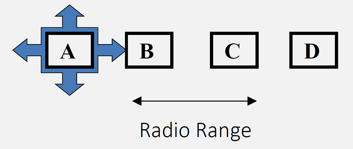
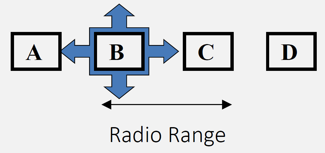
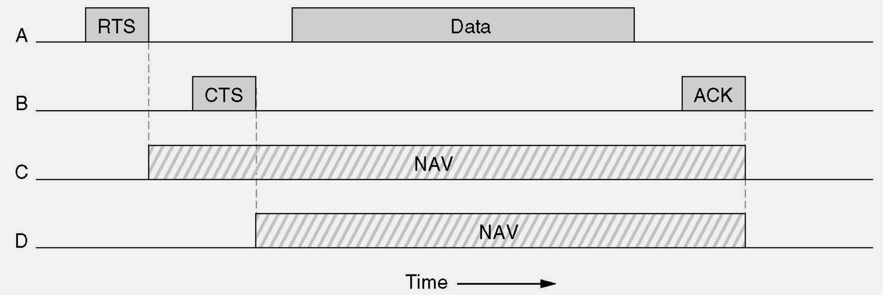
  • Solve Hidden Terminal: Apply RTS/CTS handshake to prevent collisions
  • Configure QoS: Implement traffic differentiation for IoT applications

839.2 Prerequisites

Before diving into this chapter, you should be familiar with:

  • Wi-Fi Architecture Modes: Understanding infrastructure mode, Wi-Fi Direct, and mesh networking provides context for MAC layer operation
  • Networking Basics: Knowledge of MAC layer concepts and wireless communication fundamentals
NoteKey Takeaway

In one sentence: Wi-Fi uses CSMA/CA (Carrier Sense Multiple Access with Collision Avoidance) to share the wireless medium, with RTS/CTS handshakes solving hidden terminal problems and QoS providing priority-based channel access.

Remember this rule: CSMA/CA listens before transmitting, RTS/CTS reserves the channel, and QoS ensures time-sensitive traffic (voice, video) gets priority over bulk data transfers.

Deep Dives: - Wi-Fi Architecture Modes - Infrastructure, Direct, Mesh - Wi-Fi Mesh Applications - Real-world deployments - Wi-Fi Security and Provisioning - WPA2/WPA3

Architecture Context: - Wireless Sensor Networks - WSN MAC protocols - Network Topologies - Understanding topology impact on MAC

Learning Resources: - Quizzes Hub - Test CSMA/CA knowledge - Videos Hub - MAC layer tutorials

839.3 MAC Layer and Channel Access (Summary)

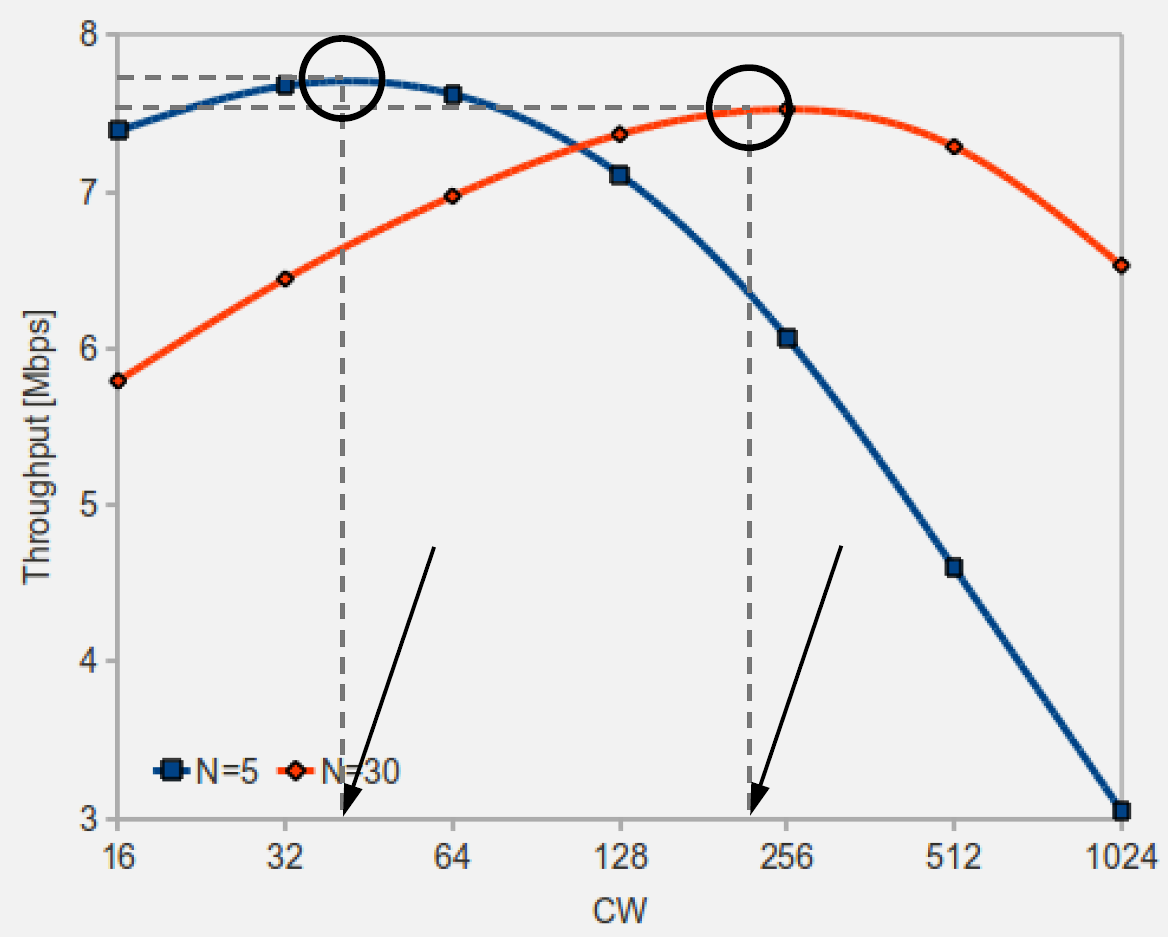
Wi-Fi uses CSMA/CA to share the medium. Hidden and exposed terminal problems can cause collisions or unnecessary backoff; RTS/CTS can mitigate hidden terminals. QoS and MAC performance depend on contention, interference, and client mix.

Wi-Fi Architecture Diagram 3

Wi-Fi Architecture Diagram 3
Figure 839.1: Wi-Fi CSMA/CA channel access with carrier sense and backoff
Flowchart showing 802.11 CSMA/CA channel access procedure with carrier sense, DIFS waiting, random backoff timer, frame transmission, and ACK receipt stages
Figure 839.2: IEEE 802.11 channel access mechanism using CSMA/CA for collision avoidance. The diagram shows a station sensing the channel carrier signal. If idle, the device waits for DIFS duration plus random backoff, then transmits the frame and waits for ACK acknowledgment. If busy, the station defers transmission and enters exponential backoff, preventing collisions through randomized retry timing.

Original textbook diagram showing IEEE 802.11 CSMA/CA channel access mechanism with carrier sense, DIFS, random backoff, and ACK procedures from CP IoT System Design Guide Chapter 4

Original 802.11 channel access diagram from CP IoT System Design Guide

Source: CP IoT System Design Guide, Chapter 4 - Networking

Network diagram showing hidden terminal problem with two stations A and B on opposite sides of access point, both transmitting simultaneously, causing collision at AP because A and B cannot hear each other
Figure 839.3: Hidden terminal problem where two stations cannot sense each other’s transmissions (due to distance, obstacles, or low SNR) but both can reach the same access point. If they transmit at the same time, their frames can collide at the AP, causing retransmissions and wasted airtime.
Network topology showing exposed terminal problem where Node B unnecessarily defers transmission because it senses Node A transmitting, even though B's transmission to Node C would not cause interference
Figure 839.4: Exposed terminal problem where a node unnecessarily defers transmission. Node B is within range of transmitting Node A and detects A’s transmission. B defers its own transmission to Node C even though B→C transmission would not interfere with A’s transmission to the AP. This reduces network efficiency as B unnecessarily waits when parallel transmissions are possible. Occurs when CSMA sensing is overly conservative.
Sequence diagram of RTS/CTS handshake showing four-step process: RTS request, CTS broadcast, NAV timer setting, and protected data transmission
Figure 839.5: RTS/CTS handshake mechanism for collision avoidance in Wi-Fi. The four-way handshake prevents hidden terminal collisions: (1) Sender transmits Request-To-Send with duration, (2) Receiver responds with Clear-To-Send heard by all nearby nodes, (3) Other nodes set NAV timer and defer transmission, (4) Sender transmits data frame safely. CTS broadcast alerts hidden terminals to wait, reducing collisions at the cost of additional overhead. Essential for mesh networks with multi-hop hidden terminals.
Performance graph showing 802.11 MAC throughput vs number of stations, with curves for saturation throughput, collision rate, and average delay as node count increases from 1 to 100
Figure 839.6: 802.11 MAC layer performance characteristics and metrics. The figure illustrates that as the number of contending stations increases (often modeled under saturation assumptions), collision probability and backoff overhead rise and effective throughput per station decreases. Exact curves depend on PHY rate, frame sizes, retry limits, and traffic patterns.

Original textbook graph showing 802.11 MAC layer performance characteristics including throughput vs station count, collision probability curves, and backoff delay metrics from CP IoT System Design Guide Chapter 4

Original 802.11 MAC performance diagram from CP IoT System Design Guide

Source: CP IoT System Design Guide, Chapter 4 - Networking

839.4 Wi-Fi Architecture for IoT

⏱️ ~20 min | ⭐⭐ Intermediate | 📋 P08.C33.U01

839.4.1 Infrastructure Mode (Most Common)

Wi-Fi Architecture Diagram 4

Wi-Fi Architecture Diagram 4
Figure 839.7: Wi-Fi infrastructure mode with access point connecting devices to Internet

This variant shows the same three Wi-Fi architectures from a spatial coverage perspective - emphasizing how each mode extends or limits coverage area.

Diagram: INFRA

Diagram: INFRA
Figure 839.8: Wi-Fi architectures compared by coverage area: Infrastructure (single room), Direct (two devices), Mesh (whole building)

Key Insight: Choose architecture based on coverage needs: Infrastructure for single room with good AP placement, Wi-Fi Direct for temporary device-to-device links, Mesh for large areas with multiple rooms or floors. Mesh eliminates dead zones through overlapping coverage.

Characteristics:

Detailed 802.11 frame structure diagram showing MAC header fields including frame control, duration, three address fields, sequence control, frame body payload section, and 4-byte FCS checksum
Figure 839.9: IEEE 802.11 frame structure showing MAC header, frame body, and FCS components. The frame consists of three main parts: (1) MAC Header with frame control, duration, addresses (source, destination, BSSID), and sequence control totaling 24-30 bytes, (2) Frame Body containing 0-2312 bytes of payload data with encryption if enabled, (3) Frame Check Sequence (FCS) providing 4-byte CRC32 checksum for error detection. Key header fields include frame type (management, control, data), fragmentation bits, retry flag, power management bit, and QoS priority fields.

Original textbook diagram showing IEEE 802.11 MAC frame structure with detailed header fields, frame body, and FCS components from CP IoT System Design Guide Chapter 4

Original 802.11 frame structure diagram from CP IoT System Design Guide

Source: CP IoT System Design Guide, Chapter 4 - Networking

  • Centralized access point (AP) or router
  • All devices connect to AP
  • AP provides DHCP, routing, internet access
  • Most common for home/office IoT

839.4.2 Wi-Fi Direct (Peer-to-Peer)

Diagram: PHONE

Diagram: PHONE
Figure 839.10: Wi-Fi Direct peer-to-peer connections with smartphone as group owner

Characteristics: - Direct device-to-device connection - No router required - One device acts as soft AP - Use cases: Camera to phone, phone to printer

839.4.3 Wi-Fi Mesh Networks

Diagram: GATEWAY

Diagram: GATEWAY
Figure 839.11: Wi-Fi mesh network with gateway and satellite nodes extending coverage

839.5 Videos

NoteWi-Fi and the Protocol Stack
Wi-Fi and the Protocol Stack
Lesson 4 — layering fundamentals that underpin 802.11 networking.
QoS traffic differentiation diagram showing four access categories (Voice, Video, Best Effort, Background) with different AIFS waiting periods and contention window ranges, illustrating priority-based channel access in 802.11e
Figure 839.12: Statistical traffic differentiation for QoS in Wi-Fi networks. The diagram shows how 802.11e QoS assigns different priority levels to traffic types using four Access Categories (AC): (1) AC_VO (Voice) highest priority with shortest wait times for VoIP calls, (2) AC_VI (Video) second priority for streaming video with bounded latency, (3) AC_BE (Best Effort) standard priority for web browsing and file transfer, (4) AC_BK (Background) lowest priority for bulk data transfers and backups. Each category uses different AIFS (Arbitration Inter-Frame Space) and contention window sizes—higher priority classes wait shorter AIFS before transmitting, increasing their probability of channel access.

Characteristics: - Multiple access points form a mesh - Self-healing, automatic routing - Extended coverage for large areas - Standards/implementations: IEEE 802.11s, vendor mesh systems, ESP32 frameworks (ESP-IDF ESP-Wi-Fi-MESH, Arduino painlessMesh)

839.6 Summary

This chapter covered Wi-Fi MAC layer and protocol fundamentals:

  • CSMA/CA Channel Access: Carrier Sense Multiple Access with Collision Avoidance prevents simultaneous transmissions through listen-before-talk, but hidden terminals cause collisions without RTS/CTS
  • RTS/CTS Handshake: Request To Send / Clear To Send mitigates hidden terminal collisions by reserving airtime (other nodes defer), improving reliability at the cost of additional overhead
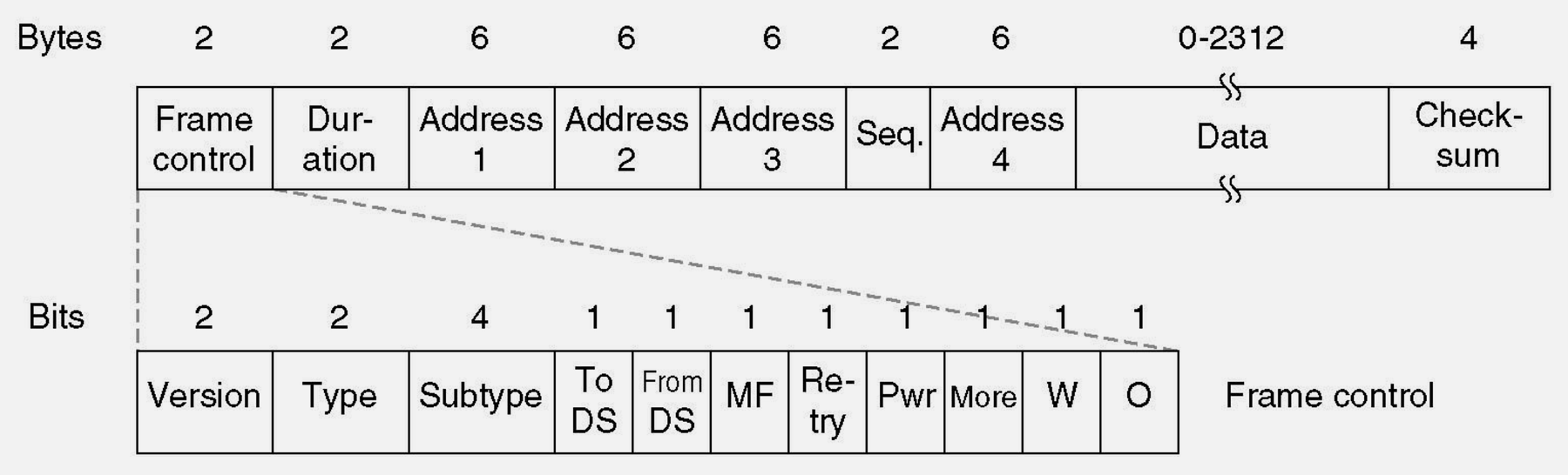
  • 802.11 Frame Structure: MAC header contains frame control, addresses, sequence control; frame body carries payload; FCS provides error detection
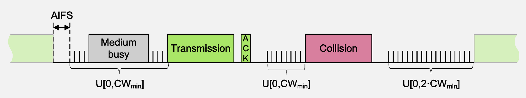
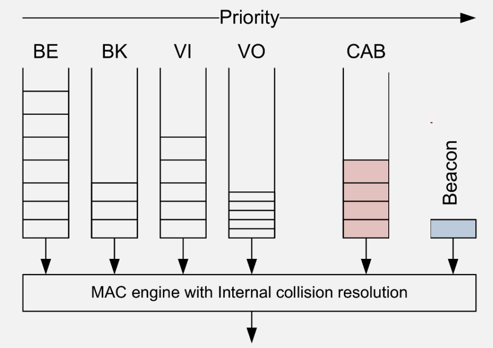
  • QoS Traffic Differentiation: 802.11e provides four access categories (Voice, Video, Best Effort, Background) with different AIFS and contention windows for priority-based channel access
  • Hidden vs Exposed Terminals: Hidden terminals cause collisions (need RTS/CTS); exposed terminals cause unnecessary backoff (reduce efficiency)

839.7 What’s Next

The next chapter explores Wi-Fi Mesh Applications, covering real-world mesh deployments, ESP32 mesh examples, IoT applications, and common pitfalls in mesh network design.