%%{init: {'theme':'base', 'themeVariables': {'primaryColor':'#2C3E50','primaryTextColor':'#fff','primaryBorderColor':'#16A085','lineColor':'#16A085','secondaryColor':'#E67E22','tertiaryColor':'#ECF0F1','fontSize':'13px'}}}%%
sequenceDiagram
participant MCU as ESP32/Arduino<br/>Master
participant SDA as SDA Line<br/>Data
participant SCL as SCL Line<br/>Clock
participant Sensor as I2C Sensor<br/>Slave (0x76)
Note over MCU,Sensor: I2C Read Transaction (BMP280 Temperature)
MCU->>SDA: START condition
MCU->>SCL: Generate clock pulses
MCU->>SDA: Device address (0x76) + WRITE
Sensor->>SDA: ACK
MCU->>SDA: Register address (0xFA)
Sensor->>SDA: ACK
MCU->>SDA: REPEATED START
MCU->>SDA: Device address (0x76) + READ
Sensor->>SDA: ACK
Sensor->>SDA: Data byte 1 (MSB)
MCU->>SDA: ACK
Sensor->>SDA: Data byte 2 (LSB)
MCU->>SDA: NACK
MCU->>SDA: STOP condition
Note over MCU,Sensor: Multiple sensors on same bus<br/>BMP280 (0x76), MPU6050 (0x68), BH1750 (0x23)
530 Light and Proximity Sensor Labs
530.1 Learning Objectives
By the end of this chapter, you will be able to:
- Interface light sensors: Configure BH1750 digital lux meter and LDR analog sensors
- Build proximity detection: Use PIR motion sensors and HC-SR04 ultrasonic distance sensors
- Understand touch sensing: Learn capacitive and skin-inspired tactile sensor technologies
- Master I2C communication: Scan buses, address multiple sensors, and debug communication issues
- Apply circuit fundamentals: Use voltage dividers, RC filters, and transistor switching in sensor circuits
530.2 Prerequisites
Required Knowledge:
- Motion & Environmental Sensors - I2C basics
- Electronics Basics - Circuit fundamentals
- Sensor Circuits - Signal conditioning
Hardware Requirements:
- ESP32 development board
- BH1750 light sensor or LDR (photoresistor)
- PIR motion sensor (HC-SR501)
- HC-SR04 ultrasonic distance sensor
- Resistors (10kOhm for voltage divider, 4.7kOhm for I2C)
- Breadboard and jumper wires
530.3 Light Sensors
530.3.1 BH1750 (Digital Light Intensity)
The BH1750 is a digital ambient light sensor with spectral response close to the human eye, making it ideal for automatic brightness adjustment.
Specifications:
- Range: 1-65535 lux
- Interface: I2C
- Resolution: 1 lux
- Spectral response close to human eye
- Power: 120uA active, 0.01uA power down
ESP32 Implementation:
#include <Wire.h>
#include <BH1750.h>

BH1750 lightMeter;

void setup() {
  Serial.begin(115200);
  Wire.begin();

  if (lightMeter.begin(BH1750::CONTINUOUS_HIGH_RES_MODE)) {
    Serial.println("BH1750 initialized");
  } else {
    Serial.println("Error initializing BH1750");
  }
}

void loop() {
  float lux = lightMeter.readLightLevel();

  Serial.print("Light: ");
  Serial.print(lux);
  Serial.print(" lux");

  // Classify light levels
  String classification;
  if (lux < 1) {
    classification = "Darkness";
  } else if (lux < 50) {
    classification = "Very dim (moonlight)";
  } else if (lux < 200) {
    classification = "Dim (hallway)";
  } else if (lux < 400) {
    classification = "Normal (office)";
  } else if (lux < 1000) {
    classification = "Bright (retail)";
  } else if (lux < 10000) {
    classification = "Very bright (overcast day)";
  } else {
    classification = "Extremely bright (direct sun)";
  }

  Serial.print(" - ");
  Serial.println(classification);

  delay(1000);
}
TipLearning Points: Light Sensing
Lux Reference Values:
| Condition | Lux Level |
|---|---|
| Full moon | 0.1-1 |
| Street lighting | 10-50 |
| Home lighting | 150-300 |
| Office | 300-500 |
| Overcast sky | 1,000-2,000 |
| Full daylight | 10,000-25,000 |
| Direct sunlight | 100,000+ |
Real-World Applications: - Smart street lights: Dim when natural light is sufficient - Display backlighting: Adjust screen brightness based on ambient light - Greenhouse automation: Supplement natural light with artificial lighting - Energy efficiency: Reduce power when full brightness isn’t needed
530.4 Proximity & Presence Sensors
530.4.1 PIR Motion Sensor (HC-SR501)
PIR (Passive Infrared) sensors detect motion by measuring changes in infrared radiation from warm bodies (humans, animals).
Specifications:
- Detection Range: 3-7 meters (adjustable)
- Detection Angle: 110 degree cone
- Output: Digital HIGH when motion detected
- Delay Time: 0.3 to 200 seconds (adjustable)
- Power: 5V, 65mA
- Trigger Modes: Single trigger or repeatable trigger
ESP32 Implementation:
#define PIR_PIN 13  // GPIO13 for PIR sensor

bool motionDetected = false;
unsigned long lastMotionTime = 0;

void setup() {
  Serial.begin(115200);
  pinMode(PIR_PIN, INPUT);

  Serial.println("PIR Motion Sensor Test");
  Serial.println("Warming up sensor (60 seconds)...");
  delay(60000);  // PIR needs 60s warm-up time
  Serial.println("Ready!");
}

void loop() {
  int pirState = digitalRead(PIR_PIN);

  if (pirState == HIGH) {
    if (!motionDetected) {
      motionDetected = true;
      lastMotionTime = millis();

      Serial.println("MOTION DETECTED!");
      Serial.print("Time: ");
      Serial.println(millis() / 1000);

      // Trigger action (turn on light, send alert, etc.)
      digitalWrite(LED_BUILTIN, HIGH);
    }
  } else {
    if (motionDetected) {
      unsigned long motionDuration = (millis() - lastMotionTime) / 1000;
      Serial.print("Motion ended. Duration: ");
      Serial.print(motionDuration);
      Serial.println(" seconds");

      motionDetected = false;
      digitalWrite(LED_BUILTIN, LOW);
    }
  }

  delay(100);
}
TipLearning Points: PIR Sensors
Key Characteristics: - PIR sensors need a 30-60 second warm-up period after power-on - Output is digital (HIGH/LOW), making interfacing very simple - The sensor stays HIGH as long as motion is detected - Adjustable potentiometers control sensitivity and hold time
Real-World Applications: - Smart lighting: Turn on lights when someone enters a room - Security systems: Send alerts when motion detected while away - Energy saving: Power down devices when no one is present - Occupancy counting: Track room usage patterns
530.4.2 Ultrasonic Distance Sensor (HC-SR04)
Ultrasonic sensors measure distance by timing the echo return of a 40kHz sound pulse.
Specifications:
- Range: 2cm to 400cm
- Accuracy: +/-3mm
- Measuring angle: 15 degrees
- Trigger pulse: 10us
- Power: 5V, 15mA
ESP32 Implementation:
#define TRIG_PIN 5
#define ECHO_PIN 18

void setup() {
  Serial.begin(115200);
  pinMode(TRIG_PIN, OUTPUT);
  pinMode(ECHO_PIN, INPUT);
}

void loop() {
  long distance = measureDistance();

  Serial.print("Distance: ");
  Serial.print(distance);
  Serial.println(" cm");

  // Object detection
  if (distance > 0 && distance < 50) {
    Serial.println("Object detected nearby!");
  }

  delay(100);
}

long measureDistance() {
  // Send 10us pulse
  digitalWrite(TRIG_PIN, LOW);
  delayMicroseconds(2);
  digitalWrite(TRIG_PIN, HIGH);
  delayMicroseconds(10);
  digitalWrite(TRIG_PIN, LOW);

  // Measure echo pulse duration
  long duration = pulseIn(ECHO_PIN, HIGH, 30000);  // 30ms timeout

  // Calculate distance (speed of sound = 343 m/s)
  // distance = (duration * 0.0343) / 2
  long distance = duration * 0.034 / 2;

  return distance;
}
TipLearning Points: Ultrasonic Sensors
Key Concepts: - Time-of-Flight: distance = (time * speed_of_sound) / 2 - Speed of Sound: 343 m/s at 20C (0.0343 cm/us) - Temperature Compensation: Speed varies ~0.6 m/s per degree C - Blind zone: Cannot measure objects closer than 2cm
Real-World Applications: - Parking sensors: Alert drivers to obstacles - Robotics: Obstacle avoidance and navigation - Liquid level sensing: Measure tank fill levels - People counting: Detect presence at doorways
Temperature Compensation Formula:
float speed_of_sound = 331.3 + (0.606 * temp_celsius); // m/s
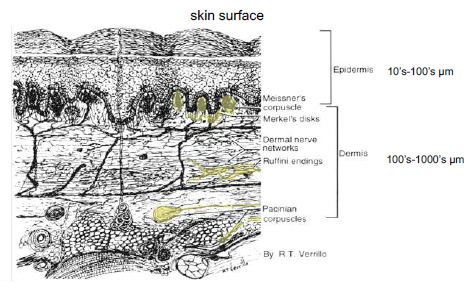
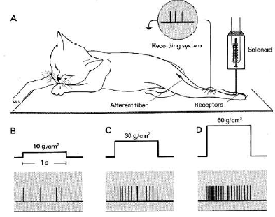
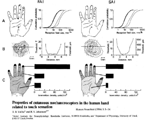
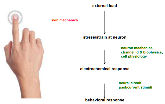
float distance_cm = (pulse_duration_us * speed_of_sound) / 20000;530.5 Touch and Skin Sensing
530.6 I2C Sensors and Bus Management
I2C Bus Scanner:
#include <Wire.h>

#define I2C_SDA 21
#define I2C_SCL 22

void setup() {
  Serial.begin(115200);
  Wire.begin(I2C_SDA, I2C_SCL);

  // Scan I2C bus
  scanI2C();
}

void scanI2C() {
  Serial.println("Scanning I2C bus...");
  int devices = 0;

  for(byte address = 1; address < 127; address++) {
    Wire.beginTransmission(address);
    byte error = Wire.endTransmission();

    if (error == 0) {
      Serial.print("I2C device found at 0x");
      if (address < 16) Serial.print("0");
      Serial.println(address, HEX);
      devices++;
    }
  }

  Serial.print("Found ");
  Serial.print(devices);
  Serial.println(" devices");
}

void loop() {
  // Empty loop
}
530.7 Circuit Fundamentals for Sensors
530.7.1 Voltage Divider with LDR
For analog light sensors (LDR/photoresistor), use a voltage divider circuit:
VCC (3.3V) ----[LDR]----+----[10kOhm]---- GND
                        |
                      ADC Pin
How it works: - LDR resistance decreases with more light (200 Ohm bright, 10k Ohm dark) - Voltage at midpoint varies with light level - ADC reads this varying voltage
530.7.2 RC Low-Pass Filter
Filter high-frequency noise from sensor readings:
Sensor Output ----[10kOhm]----+---- ADC Pin
                              |
                         [100nF]
                              |
                             GND
Cutoff Frequency: f_c = 1 / (2 * PI * R * C) = 159 Hz
TipLearning Points: Circuit Fundamentals
Voltage Divider Formula:
V_out = V_in * (R2 / (R1 + R2))RC Filter Time Constant:
tau = R * C
5*tau = time to reach steady state
Why Use Pull-up Resistors for I2C: I2C uses open-drain outputs that can only pull LOW. Pull-up resistors (4.7k Ohm typical) pull the line HIGH when no device is transmitting.
530.8 Interactive Simulator: Sensor-Controlled Servo
Try it yourself! See how sensors control actuators for automated systems.
What This Simulates: An LDR light sensor controlling a servo motor to automatically adjust window blinds based on sunlight.
How to Use: 1. Click Start Simulation 2. Click on the LDR sensor to adjust light levels 3. Watch the servo motor rotate as light changes 4. Observe the Serial Monitor showing light levels and servo angles
530.9 Knowledge Check
Question 1: Why are pull-up resistors required for I2C communication?
Explanation: I2C devices use open-drain outputs. They can pull the line LOW but cannot drive it HIGH. Pull-up resistors (typically 4.7k Ohm) are needed to pull the line HIGH when no device is transmitting.
Question 2: Your smart parking system uses ultrasonic sensors (HC-SR04). In summer (35C), the sensor reports cars 10cm closer than reality. In winter (0C), cars appear 10cm farther. What’s wrong?
Explanation: Speed of sound varies with temperature: v = 331.3 + (0.606 * T) m/s. At 0C: 331.3 m/s. At 35C: 352.5 m/s (+6.4%). Without temperature compensation, distance calculations will be incorrect. Solution: Add a temperature sensor and compensate in software.
Question 3: You’re choosing between a thermistor (NTC, analog output) and DS18B20 (digital, 1-Wire) for an outdoor weather station. The ESP32 is in a weatherproof box, sensor is 10m away on exposed pole. Which is better and why?
Explanation: Digital sensors are far superior for long-distance deployment due to noise immunity. Over 10m cable, analog signals pick up EMI, suffer voltage drops, and ground potential differences. Digital 1-Wire sends binary data that’s either correctly received or rejected via CRC.
530.10 Summary
This chapter covered light and proximity sensor implementation:
- BH1750 provides calibrated lux measurements with spectral response matching human vision
- PIR sensors detect motion via infrared radiation changes with simple digital output
- Ultrasonic HC-SR04 measures distance using time-of-flight with temperature compensation needed
- I2C bus scanning identifies connected sensors and verifies communication
- Voltage dividers convert variable resistance (LDR) to measurable voltage
- RC filters reduce high-frequency noise from analog sensor readings
530.11 What’s Next?
Continue to best practices and hands-on labs for complete sensor implementation guidance.
530.12 See Also
- Temperature Sensor Labs - Temperature sensing fundamentals
- Motion & Environmental Sensors - IMU and barometric sensing
- Sensor Calibration Lab - Hands-on calibration techniques