%% fig-alt: "Generic IoT device block diagram showing six major subsystems: Wireless Transceiver (antenna, RF front-end), Energy Management (battery, solar panel, power regulation showing 1000mAh battery with 11.4µA sleep current), Accelerators and Microcontroller (CPU, hardware accelerators), Memory (RAM, Flash), Mixed-Signal Interfaces (ADC, DAC, GPIO), and Sensors/Actuators (physical world interface). All blocks interconnected via internal buses."
%%{init: {'theme':'base', 'themeVariables': {'primaryColor':'#2C3E50','primaryTextColor':'#fff','primaryBorderColor':'#16A085','lineColor':'#16A085','secondaryColor':'#E67E22','tertiaryColor':'#ECF0F1','fontSize':'14px'}}}%%
flowchart TB
subgraph device["IoT Device Architecture"]
ANT["📡 Wireless<br/>Transceiver"]
MCU["🧠 Accelerators &<br/>Microcontroller"]
MEM["💾 Memory<br/>(RAM + Flash)"]
PWR["🔋 Energy<br/>Management"]
MIX["⚡ Mixed-Signal<br/>Interfaces"]
SENS["📊 Sensors &<br/>Actuators"]
end
subgraph power["Power Sources"]
BAT["🔋 Battery<br/>1000mAh"]
SOL["☀️ Solar<br/>Panel"]
end
ANT <--> MCU
MCU <--> MEM
MCU <--> MIX
MIX <--> SENS
PWR --> ANT
PWR --> MCU
PWR --> MEM
PWR --> MIX
BAT --> PWR
SOL --> PWR
style ANT fill:#E67E22,stroke:#2C3E50,color:#fff
style MCU fill:#2C3E50,stroke:#16A085,color:#fff
style MEM fill:#7F8C8D,stroke:#2C3E50,color:#fff
style PWR fill:#16A085,stroke:#2C3E50,color:#fff
style MIX fill:#E67E22,stroke:#2C3E50,color:#fff
style SENS fill:#16A085,stroke:#2C3E50,color:#fff
style BAT fill:#16A085,stroke:#2C3E50,color:#fff
style SOL fill:#E67E22,stroke:#2C3E50,color:#fff
594 Conductors, Insulators, and Semiconductors
594.1 Conductors, Insulators, and Semiconductors
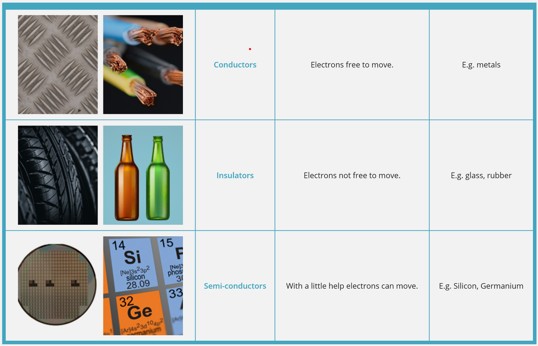
Materials behave differently when it comes to conducting electricity:
594.1.1 Electronic Components Taxonomy
Before diving into materials, let’s understand how electronic components are classified in IoT systems:

TipPassive Components: R, C, L Engineering Reference
The three passive components—resistors, capacitors, and inductors—behave differently in circuits. Understanding their properties is essential for IoT design.
| Property | Resistor (R) | Capacitor (C) | Inductor (L) |
|---|---|---|---|
| Circuit Symbol | ⏛ (zigzag) | ⏥ (parallel plates) | ⏚ (coil) |
| I-V Relationship | V = R·I | I = C·dV/dt | V = L·dI/dt |
| Unit | Ohm (Ω) | Farad (F) = C/V | Henry (H) = V·s/A |
| Impedance Z | Z = R | Z = 1/(j2πfC) | Z = j2πfL |
| Power Loss | P = I²R = V²/R | 0 (ideal) | 0 (ideal) |
| Energy Storage | 0 (dissipates heat) | W = ½CV² | W = ½LI² |
| Frequency Response | Constant | Passes high freq, blocks DC | Passes DC, blocks high freq |
Why This Matters for IoT:
| Component | IoT Application | Example |
|---|---|---|
| Resistor | Current limiting, voltage dividers, pull-ups | LED current limiting (220Ω), sensor pull-up (4.7kΩ) |
| Capacitor | Power filtering, decoupling, timing | 100nF decoupling on MCU VCC, 1000µF bulk capacitor |
| Inductor | EMI filtering, DC-DC conversion, antennas | Switching regulator, PCB antenna matching |
Key Formulas for IoT Design:
- RC Time Constant: τ = R × C (seconds)
- Used for: Button debouncing, ADC sample timing
- Example: 10kΩ × 100nF = 1ms
- LC Resonant Frequency: f = 1/(2π√(LC))
- Used for: RF tuning, antenna matching
- Example: 1µH × 10pF → 50MHz
- Capacitor Energy: W = ½CV²
- Used for: Backup power calculations
- Example: 1000µF × 3.3V² = 5.4mJ (powers MCU for ~50ms during brownout)
NoteComponent Quick Reference
594.1.2 Schematic Symbol to Real Component Guide
Learning to read schematics requires mapping symbols to physical components:
| Component | Symbol Description | Physical Appearance | Key Specs to Know |
|---|---|---|---|
| Resistor | Zigzag line or rectangle | Cylinder with color bands | Ohms (Ω), Power rating (W) |
| Capacitor | Two parallel lines | Cylinder or disc | Capacitance (µF), Voltage rating |
| LED | Triangle with arrow + light rays | Clear/colored dome | Forward voltage (Vf), Max current |
| Transistor | Circle with 3 leads (NPN/PNP) | TO-92 or SMD package | hFE (gain), Vce max |
| Diode | Triangle pointing to line | Glass cylinder with stripe | Forward voltage, Max current |
| Inductor | Coiled line | Wire-wound cylinder | Inductance (µH/mH) |
Reading color codes (resistors): - Black=0, Brown=1, Red=2, Orange=3, Yellow=4 - Green=5, Blue=6, Violet=7, Gray=8, White=9 - Gold=5% tolerance, Silver=10%
Example: Brown-Black-Red = 10 × 10² = 1000Ω = 1kΩ
594.1.3 IoT Component Visual Dictionary

A comprehensive reference guide for selecting and using electronic components in IoT projects. This section provides practical specifications and real-world use cases.
594.1.3.1 Essential Passive Components
| Component | Symbol | Function | IoT Use Case | Typical Values |
|---|---|---|---|---|
| Resistor | ─/\/\/─ |
Limits current flow | LED current limiting | 220Ω-10kΩ |
| Capacitor | ─ǁ─ |
Stores electrical charge | Power supply smoothing | 100nF-1000µF |
| Inductor | ─∿∿∿─ |
Stores magnetic energy | Switching regulators, EMI filtering | 10µH-100mH |
| Diode | ─▷│─ |
One-way current flow | Reverse polarity protection | 1N4001, 1N4148 |
| LED | ─▷│─ (light) |
Light output | Status indicators, displays | Red: 1.8-2.2V, Blue: 3.0-3.4V |
Passive Component Selection Rules:
- Resistors: Always check power rating (P = I² × R). Common: 1/8W, 1/4W, 1/2W
- Capacitors: Voltage rating must be ≥ 2× operating voltage for reliability
- Inductors: Saturation current must exceed maximum expected current
- Diodes: Forward voltage (Vf) affects efficiency; Schottky diodes have lower Vf (0.3V vs 0.7V)
- LEDs: Always use current-limiting resistor. Formula: R = (Vsupply - Vf) / Iled
594.1.3.2 Essential Active Components
| Component | Function | IoT Use Case | Popular Parts | Key Specs |
|---|---|---|---|---|
| Transistor (NPN) | Switch/amplify small signals | Driving motors, relays | 2N2222, BC547 | Ic=800mA, hFE=100-300 |
| Transistor (PNP) | High-side switching | Load switching | 2N2907, BC557 | Ic=600mA, hFE=100-300 |
| MOSFET (N-channel) | High-current power switching | Motors, LED strips, solenoids | IRF540, AO3400 | Id=10-30A, RDS(on)=0.01-0.1Ω |
| MOSFET (P-channel) | High-side load control | Reverse polarity protection | IRF9540, AO3401 | Id=10-20A, higher RDS(on) |
| Op-Amp | Signal conditioning | Sensor amplification, filtering | LM358, MCP6002 | Rail-to-rail, low offset |
| Voltage Regulator (Linear) | Stable DC voltage | 3.3V/5V from battery | AMS1117, LM7805 | Dropout: 1-1.5V, efficiency 50-60% |
| Voltage Regulator (Switching) | Efficient power conversion | Battery-powered IoT nodes | TPS62130, LM2596 | Efficiency: 85-95%, lower quiescent current |
Active Component Selection Rules:
- BJT vs MOSFET: Use BJT for <1A, MOSFET for >1A (lower switching losses)
- Logic-Level MOSFETs: Required for 3.3V/5V GPIO control (Vgs(th) < 2.5V)
- Op-Amp Power: Choose rail-to-rail for single-supply IoT applications


- Linear vs Switching Regulator: Linear for low noise (<100mA), Switching for efficiency (>100mA)
594.1.3.3 Common IoT Circuit Patterns
These circuit patterns solve 90% of IoT interface challenges:
| Circuit Pattern | Purpose | When to Use | Formula/Notes |
|---|---|---|---|
| Voltage Divider | Scale voltage down | Sensor output > ADC range, 5V→3.3V level shift | Vout = Vin × (R2 / (R1 + R2)) |
| Pull-up Resistor | Ensure defined logic HIGH | I2C, open-drain outputs, buttons | 4.7kΩ-10kΩ typical, lower for faster switching |
| Pull-down Resistor | Ensure defined logic LOW | GPIO floating inputs, reset pins | 10kΩ-100kΩ typical |
| Decoupling Capacitor | Reduce power supply noise | Every IC power pin | 100nF ceramic + 10µF electrolytic |
| Level Shifter | Bidirectional 3.3V ↔︎ 5V | I2C, SPI, UART voltage mismatch | Use BSS138 MOSFET or TXS0108E IC |
| Current Limiting (LED) | Prevent LED burnout | All LED circuits | R = (Vsupply - Vf) / Iled |
| Flyback Diode | Suppress inductive kickback | Motors, relays, solenoids | 1N4001-1N4007 across coil |
| RC Low-Pass Filter | Remove high-frequency noise | Analog sensor inputs | fc = 1 / (2π × R × C) |
594.1.3.4 Quick IoT Component Selection Guide
For Beginners - Start Here:
| Goal | Component Combo | Example Circuit |
|---|---|---|
| Status indicator | LED + Resistor | GPIO → 220Ω resistor → LED → GND |
| Speed control | Transistor + Motor | GPIO → 1kΩ → NPN base, Motor between Vcc and collector |
| Stable power | Capacitor + Regulator | Battery → AMS1117-3.3 → 10µF cap → ESP32 |
| Sensor interface | Voltage divider | 5V sensor → 10kΩ → ADC pin → 10kΩ → GND |
| High-current load | MOSFET + Gate resistor | GPIO → 100Ω → MOSFET gate, Load between Vcc and drain |
594.1.3.5 Component Rating Guidelines
Critical Safety Rules - Prevent Component Damage:
| Parameter | Selection Rule | Example | Why It Matters |
|---|---|---|---|
| Voltage Rating | Choose ≥ 2× expected voltage | 12V supply → use 25V+ capacitor | Voltage spikes can exceed nominal |
| Current Rating | Choose ≥ 1.5× expected current | 1A motor → use 1.5A+ transistor | Prevent overheating and failure |
| Power Rating (Watts) | Must exceed P = I² × R or P = V × I | 5V, 20mA LED → R=150Ω → P=0.1W → use 1/4W (0.25W) resistor | Insufficient rating → burnout |
| Temperature Rating | Match environment | Outdoor sensor: -40°C to +85°C rated components | Consumer-grade (0-70°C) fails in harsh conditions |
| Package Size | Consider PCB design | 0402, 0805 (SMD) or through-hole | Smaller = harder to hand-solder |
Real-World Temperature Derating:
- Commercial: 0°C to 70°C (indoor IoT devices)
- Industrial: -40°C to 85°C (outdoor sensors, automotive)
- Military: -55°C to 125°C (extreme environments)
Common Mistakes to Avoid:
- ❌ “Any resistor will work” → ✓ Calculate exact value and power rating
- ❌ Using 5V sensor with 3.3V ADC directly → ✓ Add voltage divider or level shifter
- ❌ Connecting motor directly to GPIO → ✓ Use transistor/MOSFET switch
- ❌ Forgetting flyback diode on relay → ✓ Always add 1N4007 across coil
- ❌ No decoupling capacitor on MCU → ✓ Add 100nF at each Vcc pin
594.1.3.6 Quick Component Calculations
LED Current Limiting:
Given: ESP32 GPIO (3.3V), Red LED (Vf=2.0V), desired current 10mA
R = (Vsupply - Vf) / I = (3.3 - 2.0) / 0.010 = 130Ω → use 150Ω (standard value)
Power: P = I² × R = (0.01)² × 150 = 0.015W → use 1/8W resistor
Voltage Divider for 5V→3.3V:
Given: 5V sensor output, 3.3V max ADC input
Vout = Vin × (R2 / (R1 + R2))
3.3 = 5 × (R2 / (R1 + R2))
Choose R2 = 10kΩ, then R1 = 5.15kΩ → use 5.1kΩ (standard value)
Verify: 5 × (10k / (5.1k + 10k)) = 3.31V ✓
Decoupling Capacitor Value:
Rule of thumb: C = I × t / ΔV
For MCU drawing 100mA with 10ns switching, allow 0.1V droop:
C = 0.1 × 10×10⁻⁹ / 0.1 = 10nF → use 100nF for safety margin
Component Selection Summary Table:
| Scenario | Recommended Components | Key Specs | Notes |
|---|---|---|---|
| Low-current indicator (<20mA) | Standard LED + resistor | 220Ω-1kΩ, 1/8W | Simple and reliable |
| Medium current load (100mA-1A) | NPN transistor (2N2222) | Ic=800mA, hFE>100 | Add base resistor |
| High current load (>1A) | Logic-level N-MOSFET | RDS(on)<0.1Ω, Vgs(th)<2.5V | IRF540, IRLZ44N |
| Inductive load (motor, relay) | MOSFET + flyback diode | 1N4007 diode | Prevents voltage spikes |
| 3.3V from battery (low noise) | Linear LDO regulator | AMS1117-3.3, 1A max | Simple, low noise |
| 3.3V from battery (efficient) | Buck converter | TPS62130, 85-95% efficient | Longer battery life |
| Sensor signal amplification | Rail-to-rail op-amp | LM358, MCP6002 | Single supply compatible |
| 5V↔︎3.3V bidirectional | Logic level shifter IC | TXS0108E, BSS138 | I2C, SPI safe conversion |
Pro Tips for Component Selection:
- Start with reference designs: Most sensor/module datasheets include recommended circuits
- Use standard values: Resistors (E12 series: 10, 12, 15, 18, 22, 27, 33, 39, 47, 56, 68, 82)
- Buy assortment kits: Get common values (resistors, capacitors, transistors) for prototyping
- Check package availability: Through-hole for breadboarding, SMD for final PCB
- Read the datasheet: Absolute maximum ratings, recommended operating conditions, typical circuits
TipGeneric IoT Device Architecture
Every IoT device follows a similar block architecture, regardless of whether it’s a simple sensor node or complex gateway:
Subsystem Functions:
| Subsystem | Function | Power Consumption | Example Components |
|---|---|---|---|
| Wireless Transceiver | RF communication | 10-100mA (TX), 5-20mA (RX) | ESP32 Wi-Fi, SX1276 LoRa, nRF52 BLE |
| Microcontroller | Program execution, logic | 1-50mA (active), 1-50µA (sleep) | ARM Cortex-M0/M4, ESP32, ATmega |
| Memory | Code and data storage | Included in MCU | Flash (program), SRAM (data) |
| Energy Management | Voltage regulation, charging | 1-10µA overhead | LDO, DC-DC converter, PMIC |
| Mixed-Signal | ADC, DAC, comparators | 10-100µA per channel | Built into MCU or external ICs |
| Sensors/Actuators | Physical world interface | 1µA - 100mA (varies widely) | BME280, DHT22, motors, LEDs |
Real Numbers - Ultra-Low-Power Design:
With a 1000mAh battery and 11.4µA average sleep current: - Battery Life = 1000mAh / 0.0114mA = 87,719 hours = 10 years
This is achievable when: - Sleep mode 99.9% of time - Wake briefly (100ms) every 15 minutes - Transmit data once per hour
594.1.4 Material Classification
%%{init: {'theme': 'base', 'themeVariables': { 'primaryColor': '#2C3E50', 'primaryTextColor': '#fff', 'primaryBorderColor': '#1A252F', 'lineColor': '#2C3E50', 'secondaryColor': '#16A085', 'tertiaryColor': '#E67E22', 'noteTextColor': '#2C3E50', 'noteBkgColor': '#ECF0F1', 'textColor': '#2C3E50', 'fontSize': '16px'}}}%%
graph LR
    subgraph COND["Conductors"]
        C1["Free Electrons<br/>Low Resistance<br/>~10⁻⁸ Ω·m"]
        C2["Copper, Gold<br/>Aluminum"]
    end

    subgraph SEMI["Semiconductors"]
        S1["Controllable<br/>Medium Resistance<br/>Variable"]
        S2["Silicon, Germanium<br/>Gallium Arsenide"]
    end

    subgraph INSU["Insulators"]
        I1["Bound Electrons<br/>High Resistance<br/>~10¹⁵ Ω·m"]
        I2["Rubber, Glass<br/>Plastic"]
    end

    COND -.Increasing Resistance.-> SEMI
    SEMI -.Increasing Resistance.-> INSU

    style COND fill:#16A085,stroke:#138D75,color:#fff
    style SEMI fill:#E67E22,stroke:#D35400,color:#fff
    style INSU fill:#7F8C8D,stroke:#5D6D7E,color:#fff
    style C1 fill:#ECF0F1,stroke:#16A085,color:#2C3E50
    style C2 fill:#ECF0F1,stroke:#16A085,color:#2C3E50
    style S1 fill:#ECF0F1,stroke:#E67E22,color:#2C3E50
    style S2 fill:#ECF0F1,stroke:#E67E22,color:#2C3E50
    style I1 fill:#ECF0F1,stroke:#7F8C8D,color:#2C3E50
    style I2 fill:#ECF0F1,stroke:#7F8C8D,color:#2C3E50
%%{init: {'theme': 'base', 'themeVariables': { 'primaryColor': '#2C3E50', 'primaryTextColor': '#fff', 'primaryBorderColor': '#16A085', 'lineColor': '#16A085', 'secondaryColor': '#E67E22', 'tertiaryColor': '#ECF0F1', 'fontSize': '11px'}}}%%
flowchart TB
    subgraph device["IoT SENSOR NODE"]
        subgraph conductors["CONDUCTORS (Carry current)"]
            C1["PCB Copper Traces<br/>Connect components"]
            C2["Wire Leads<br/>External connections"]
            C3["Solder Joints<br/>Component mounting"]
        end

        subgraph semiconductors["SEMICONDUCTORS (Control current)"]
            S1["ESP32 Chip<br/>Millions of transistors"]
            S2["Sensor IC<br/>Signal processing"]
            S3["Voltage Regulator<br/>Power control"]
        end

        subgraph insulators["INSULATORS (Block current)"]
            I1["PCB Substrate (FR4)<br/>Isolates traces"]
            I2["Plastic Enclosure<br/>Safety barrier"]
            I3["Conformal Coating<br/>Moisture protection"]
        end
    end

    conductors --> semiconductors
    semiconductors --> insulators

    style conductors fill:#E8F5E9,stroke:#16A085
    style semiconductors fill:#FFF3E0,stroke:#E67E22
    style insulators fill:#E3F2FD,stroke:#2C3E50
{fig-alt=“Electronics diagram illustrating”Conductors”, “Free Electrons Low Resistance ~10⁻⁸ Ω·m”, “Copper, Gold Aluminum” showing semiconductor components, transistor circuits, diode operation, signal amplification, or switching circuits used in sensor and actuator interfacing for IoT systems.”}
| Type | Electron Mobility | Resistance | Examples | IoT Use |
|---|---|---|---|---|
| Conductor | Free to move | Very low (~10-8 Ω·m) | Copper, gold, aluminum | Wires, PCB traces, contacts |
| Insulator | Cannot move | Very high (~1015 Ω·m) | Rubber, glass, plastic | Cable insulation, PCB substrate |
| Semiconductor | Conditionally mobile | Medium (variable) | Silicon, germanium | Transistors, diodes, ICs |
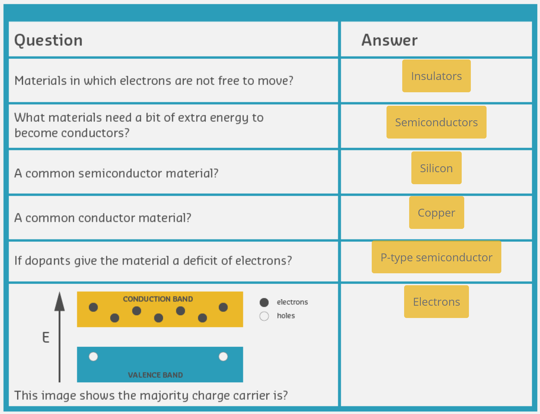
594.1.5 The Semiconductor Advantage
Key Property: Semiconductors can be switched between conducting and insulating states by applying external energy (voltage or current).
This controllability makes ALL modern electronics possible.
594.2 What’s Next?
Continue to Semiconductors and Doping to learn about N-type and P-type semiconductors, diodes, and PN junctions.