592 Electricity Fundamentals: Reference and Resources
592.1 Quiz 5: Comprehensive Review
Question 2: A solar-powered air quality monitor (ESP32 + sensors) runs continuously on 5V from a buck converter. Current measurements show 100mA average draw. The 10W solar panel provides 18V @ 555mA peak. With MPPT charging and 3000mAh battery, the system dies after 15 hours of darkness. What is the device’s actual power consumption, and does it match the battery capacity?
- 0.5W device (matches 15hr runtime: 3000mAh ÷ 100mA = 30hrs theoretical, 50% battery usable gives 15hrs)
- 50W device (severe overconsumption; battery dead in 18 minutes)
- 5W device (10× overconsumption; battery dead in 1.5 hours)
- 0.05W device (ultra-low power; battery should last 150 hours)
💡 Explanation: Power calculation: P = V × I = 5V × 0.1A = 0.5W (500mW). Battery runtime analysis: 3000mAh Li-ion @ 3.7V nominal = 11.1Wh total energy. Usable capacity: Li-ion 100% → 20% discharge = 80% usable = 8.88Wh. Device: 0.5W × 15hrs = 7.5Wh consumed ✓ Matches! Why 15 hours, not 30 hours?: (1) Buck converter efficiency: 85% typical → 0.5W / 0.85 = 0.59W drawn from battery. (2) Battery voltage sag: 3.7V nominal, but drops to 3.3V at 20% SOC → buck converter cuts off. (3) Actual runtime: 3000mAh × (3.7V avg) × 0.8 usable / 0.5W ≈ 17.8hrs. Close to 15hrs measured. Solar charging verification: 10W panel @ 5hrs sunlight/day = 50Wh generated. Device 24hrs × 0.5W = 12Wh consumed. Net surplus: 38Wh/day → Battery fully charges in 11.1Wh / 38Wh = 0.3 days (7 hours) of sun. Why system still fails: Cloudy days (2W panel output) generate 2W × 5hrs = 10Wh < 12Wh consumed → Battery slowly drains over multi-day clouds. Solution: (1) Increase panel to 20W, (2) Reduce duty cycle (sleep mode: 10mA average → 4.8× longer runtime), (3) Larger battery (6000mAh for 2-day autonomy). Key lesson: Power (Watts) = voltage × current determines both instantaneous load and daily energy budget (Watt-hours).
Question 5: A smart lighting controller drives four LED strips in parallel for redundancy. Each strip has a built-in 1kΩ current-limiting resistor. During testing, one strip fails open (disconnected), but brightness barely changes. Measuring the remaining three strips’ combined resistance shows 333Ω. If all four strips were working, what would the total resistance be, and how does this explain the minimal brightness change?
- 2kΩ (resistances add in parallel like series)
- 1kΩ (parallel resistors maintain individual resistance)
- 500Ω (parallel: R_total = R/n; four 1kΩ resistors = 250Ω, losing one → 333Ω, only 25% brightness drop)
- 250Ω (correct for four strips; one failing causes 75% brightness loss)
💡 Explanation: Parallel resistor formula: For n identical resistors in parallel, R_total = R / n. With 4 working strips: R_total = 1kΩ / 4 = 250Ω. Current: I = 12V / 250Ω = 48mA total (12mA per strip). With 3 working strips (measured): R_total = 1kΩ / 3 = 333Ω. Current: I = 12V / 333Ω = 36mA total (12mA per strip). Brightness change: 36mA / 48mA = 75% of original brightness = 25% reduction. Barely noticeable to human eye (logarithmic perception). Why parallel for redundancy: One strip fails → System continues operating at reduced capacity. In series, one strip fails → Entire system goes dark. Verification with formula: 1/R_total = 1/R1 + 1/R2 + 1/R3 + 1/R4 = 4/1kΩ = 0.004 S → R_total = 250Ω. Lose one: 1/R_total = 3/1kΩ = 0.003 S → R_total = 333Ω ✓. Power consumption change: P_4strips = V²/R = (12V)² / 250Ω = 0.576W. P_3strips = 144V² / 333Ω = 0.432W. Power drops 25% (proportional to current). Design trade-offs: Parallel: Redundant but higher total current. Series: Low current but no redundancy. Practical IoT application: Emergency lighting, critical sensors, safety systems all use parallel redundancy. Current capacity check: 48mA total < 500mA power supply rating ✓ Safe.
Question 6: A voltage divider uses 1kΩ (R1) and 3kΩ (R2) resistors to divide a 12V input. What is the output voltage across R2?
- 3V
- 4V
- 9V
- 12V
💡 Explanation: V_out = V_in × (R2 / (R1 + R2)) = 12V × (3kΩ / (1kΩ + 3kΩ)) = 12V × (3/4) = 9V. Voltage dividers are fundamental in IoT for level shifting (5V to 3.3V conversion), sensor signal conditioning, and battery voltage monitoring. The output voltage is proportional to the resistor ratio.
Question 7: An IoT sensor draws 2mA continuously from a 1000mAh battery. How long will the battery last?
- 50 hours
- 200 hours
- 500 hours
- 2000 hours
💡 Explanation: Battery Life = Battery Capacity / Current Draw = 1000mAh / 2mA = 500 hours ≈ 21 days. This calculation is critical for IoT deployment planning. In practice, account for battery inefficiency (use 80% of rated capacity), temperature effects, and voltage drop under load. Sleep modes can extend battery life 100-1000× by reducing average current draw.
Question 8: A 220Ω resistor carries 50mA (0.05A) current. How much power does it dissipate?
- 0.055W
- 0.55W
- 5.5W
- 11W
💡 Explanation: P = I² × R = (0.05A)² × 220Ω = 0.0025 × 220 = 0.55W. This resistor needs at least a 1W power rating (with 2× safety margin for reliability). Common resistor power ratings are 1/8W, 1/4W, 1/2W, 1W, and 2W. Undersized resistors overheat, change value, and can fail, causing circuit malfunction.
Question 9: In conventional current flow notation used in circuit analysis, current flows:
- From negative to positive
- From positive to negative
- In both directions simultaneously
- Only in AC circuits
💡 Explanation: By convention, current flows from positive (+) to negative (-), even though electrons physically flow from negative to positive. This historical convention (established before electron discovery) is used in all circuit analysis, design, and engineering documentation. Understanding this convention is essential for reading schematics and analyzing circuit behavior.
592.2 Visual Reference Gallery
Explore alternative visual representations of electrical fundamentals. These AI-generated figures provide different perspectives on circuits, components, and power concepts.

AI-generated modern visualization of the fundamental Ohm’s Law relationship used in all circuit analysis.

AI-generated geometric visualization explaining the physical basis of electrical current in conductors.
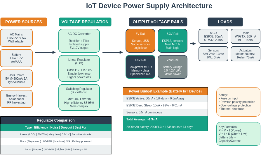
DrawIO template showing the complete power supply architecture for battery-powered IoT devices.
Decision context: When designing a power supply for an IoT device that will operate remotely or in hard-to-reach locations.
| Factor | Battery | Energy Harvesting |
|---|---|---|
| Power | Predictable, consistent output regardless of environment | Variable output depending on light, vibration, or thermal conditions |
| Cost | Lower initial cost ($1-$20 for typical IoT batteries) | Higher initial cost ($20-$100 for solar panels, harvesters, and PMICs) |
| Reliability | Finite lifespan; requires periodic replacement | Potentially infinite lifespan if properly sized for worst-case conditions |
| Maintenance | Scheduled battery replacements (months to years) | Minimal once deployed; monitor harvesting efficiency |
| Size | Scales linearly with capacity needs | Fixed harvester size; requires supercapacitor/battery buffer |
| Environmental | Disposal concerns; temperature sensitivity (-20C to 60C) | Green solution; some harvesters work in extreme temperatures |
Choose Battery when:
- Deployment is accessible for maintenance (monthly/yearly visits feasible)
- Power demand is high or unpredictable (actuators, high-bandwidth radios)
- Environmental conditions are unfavorable for harvesting (indoor, no vibration, stable temps)
- Project budget is limited and upfront cost must be minimized
Choose Energy Harvesting when:
- Device is deployed in inaccessible locations (bridges, wildlife, deep ocean)
- Ultra-long lifetime is required (10+ years maintenance-free)
- Environmental energy is abundant and consistent (outdoor solar, industrial vibration)
- Total cost of ownership matters more than initial cost (thousands of devices at scale)
Default recommendation: Battery power unless the deployment location is inaccessible OR you are deploying at scale (1000+ devices) where battery replacement costs exceed harvesting infrastructure investment.
592.3 Common Pitfalls
The mistake: Connecting multiple circuit boards or sensors using separate ground paths that create loops, introducing 50/60Hz mains interference and unexplained voltage fluctuations into sensitive analog measurements.
Symptoms: - ADC readings show periodic 50Hz or 60Hz oscillations (depending on mains frequency) - Sensor values fluctuate even with stable physical conditions - Noise increases when motors, relays, or AC equipment operates nearby - Connecting an oscilloscope probe changes the measurement (adds another ground path)
Why it happens: Ground loops form when current flows through unintended ground paths. If sensor ground and MCU ground connect at two different points, the resistance between those points creates a small voltage difference (ground noise). AC equipment induces currents in this loop through magnetic coupling, appearing as 50/60Hz interference.
The fix: Use a star ground topology–connect all ground wires to a single point near the power supply or MCU. For distributed systems, use differential signaling (twisted pairs) or isolated sensors. Add ferrite beads on ground wires to block high-frequency noise.
Prevention: Always plan your ground layout before wiring. Draw your ground connections–if you can trace a loop, break it. For sensitive analog circuits, keep analog ground (AGND) and digital ground (DGND) separate, joining only at the power supply.
The mistake: Powering sensitive analog sensors directly from a switching power supply or USB port without filtering, introducing high-frequency noise that corrupts ADC measurements.
Symptoms: - ADC readings jump by 10-50 LSBs even with stable sensor input - Noise frequency matches switching regulator frequency (typically 500kHz-2MHz) - 12-bit ADC behaves like 8-bit (effective resolution loss of 4 bits) - Problem worse when Wi-Fi or BLE radio is transmitting (current spikes)
Why it happens: Switch-mode power supplies (including USB) generate ripple at their switching frequency. This ripple couples into the ADC reference and analog inputs. A 10mV ripple on a 3.3V supply with 12-bit ADC (0.8mV/LSB) causes 12 LSB noise. Radio transmit bursts draw 200-400mA spikes, causing supply voltage dips.
The fix: Add a dedicated LDO regulator (like AMS1117-3.3 or MCP1700) for analog sensor power, with 10uF input and 10uF output capacitors. Place a 100nF ceramic capacitor directly at each sensor’s power pins. Use separate power rails for digital (noisy) and analog (quiet) sections.
Prevention: Include analog power filtering in your initial design. Budget for an LDO even when your digital supply voltage matches sensor requirements–the filtering is worth the small efficiency loss. For battery systems, the LDO dropout of 200-300mV is acceptable for the noise improvement gained.
592.4 Summary
This chapter covered the electrical fundamentals essential for IoT systems:
- Fundamental Concepts: Electricity is the flow of electrons between atoms, with current (I) measuring charge flow in amperes, voltage (V) representing electrical pressure in volts, and resistance (R) opposing current flow in ohms
- Ohm’s Law: The relationship V = I × R is fundamental to all circuit analysis, enabling calculation of any electrical parameter when two are known
- Power and Energy: Power (P = V × I) measured in watts determines energy consumption rate, critical for battery life calculations in IoT devices
- Circuit Configurations: Series circuits share the same current with voltages adding up (V_total = V1 + V2), while parallel circuits share the same voltage with currents adding up (I_total = I1 + I2)
- Resistors: Fixed resistors limit current and divide voltage (color codes indicate values), while variable resistors (potentiometers, thermistors, photoresistors) enable sensor applications
- Capacitors and Inductors: Capacitors store energy in electric fields (used for filtering and timing), while inductors store energy in magnetic fields (used in power supplies and filtering)
- Battery Calculations: Battery life = capacity (mAh) / current draw (mA), essential for determining IoT device deployment duration and sleep mode requirements
Fundamentals: - Electronics - Semiconductors, transistors, and diodes - Analog-Digital Electronics - ADC/DAC conversion
Sensing: - Sensor Fundamentals - Sensor types and power requirements - Sensor Circuits - Circuit design for sensors - Sensor Interfacing - Signal conditioning
Actuation: - Actuators - Motors, relays, and control circuits
Design: - Energy Management - Power budgeting - Context-Aware Energy - Battery optimization - Prototyping Hardware - Arduino, ESP32, Raspberry Pi
Architecture: - Wireless Sensor Networks - Network power considerations - Edge Computing - Distributed power systems
Products:
Learning: - Simulations Hub - Circuit simulators - Sensor Labs - Hands-on electrical labs
592.5 Visual Reference Library
This section contains AI-generated phantom figures designed to illustrate key concepts covered in this chapter. These figures provide visual reference material for understanding sensing and actuation systems.
Note: These are AI-generated educational illustrations meant to complement the technical content.
592.5.1 Ohm’s Law and Relationships


592.5.2 Light-Dependent Resistors

592.5.3 Power and Energy


592.6 What’s Next?
Now that you understand electrical fundamentals (voltage, current, resistance, power), you’re ready to explore electronics—the world of semiconductors, diodes, and transistors that form the building blocks of active circuits and microcontrollers.
Interactive Learning: - TinkerCAD Circuits - Free circuit simulator - PhET Circuit Simulation - Interactive physics simulations
Video Tutorials: - SparkFun: Voltage, Current, Resistance - ElectroBOOM: Electricity Explained
Reference: - All About Circuits - Comprehensive electronics textbook
Electronics Foundation: - Electronics - Electronic components - Analog-Digital Electronics - ADC/DAC
Sensing: - Sensor Circuits - Circuit design - Sensor Fundamentals - Sensor types
Power & Energy: - Energy Aware Considerations - Power budgeting - Context-Aware Energy - Power management
Prototyping: - Prototyping Hardware - Hardware platforms
Products:
Labs: - Sensor Labs - Hands-on practice