%% fig-alt: "Ohm's Wheel circular diagram showing all formulas relating Voltage (V), Current (I), Resistance (R), and Power (P) with 12 different calculation methods"
%%{init: {'theme': 'base', 'themeVariables': {'primaryColor': '#2C3E50', 'primaryTextColor': '#fff', 'primaryBorderColor': '#16A085', 'lineColor': '#E67E22', 'secondaryColor': '#16A085', 'tertiaryColor': '#f4f4f4', 'fontSize': '14px'}}}%%
graph TB
    Center["Ohm's Wheel<br/>Cover unknown<br/>to find formula"]

    Center --> V["V (Volts)"]
    Center --> I["I (Amps)"]
    Center --> R["R (Ohms)"]
    Center --> P["P (Watts)"]

    V --> V1["V = I × R"]
    V --> V2["V = P / I"]
    V --> V3["V = √(P × R)"]

    I --> I1["I = V / R"]
    I --> I2["I = P / V"]
    I --> I3["I = √(P / R)"]

    R --> R1["R = V / I"]
    R --> R2["R = V² / P"]
    R --> R3["R = P / I²"]

    P --> P1["P = V × I"]
    P --> P2["P = V² / R"]
    P --> P3["P = I² × R"]

    style Center fill:#16A085,stroke:#2C3E50,stroke-width:3px,color:#fff
    style V fill:#E67E22,stroke:#2C3E50,stroke-width:2px,color:#fff
    style I fill:#E67E22,stroke:#2C3E50,stroke-width:2px,color:#fff
    style R fill:#E67E22,stroke:#2C3E50,stroke-width:2px,color:#fff
    style P fill:#E67E22,stroke:#2C3E50,stroke-width:2px,color:#fff
    style V1 fill:#f4f4f4,stroke:#2C3E50,stroke-width:1px
    style V2 fill:#f4f4f4,stroke:#2C3E50,stroke-width:1px
    style V3 fill:#f4f4f4,stroke:#2C3E50,stroke-width:1px
    style I1 fill:#f4f4f4,stroke:#2C3E50,stroke-width:1px
    style I2 fill:#f4f4f4,stroke:#2C3E50,stroke-width:1px
    style I3 fill:#f4f4f4,stroke:#2C3E50,stroke-width:1px
    style R1 fill:#f4f4f4,stroke:#2C3E50,stroke-width:1px
    style R2 fill:#f4f4f4,stroke:#2C3E50,stroke-width:1px
    style R3 fill:#f4f4f4,stroke:#2C3E50,stroke-width:1px
    style P1 fill:#f4f4f4,stroke:#2C3E50,stroke-width:1px
    style P2 fill:#f4f4f4,stroke:#2C3E50,stroke-width:1px
    style P3 fill:#f4f4f4,stroke:#2C3E50,stroke-width:1px
590 Electricity Fundamentals: Ohm’s Law
Ohm’s Law describes the fundamental relationship between voltage, current, and resistance.
590.0.1 The Basic Equation
\[I = \frac{V}{R}\]
NoteOriginal Source Figure: Ohm’s Wheel (Alternative View)
Source: CP IoT System Design Guide, Chapter 3 - Sensing and Actuation
TipAI-Generated Figure: Ohm’s Wheel (Artistic Rendering)

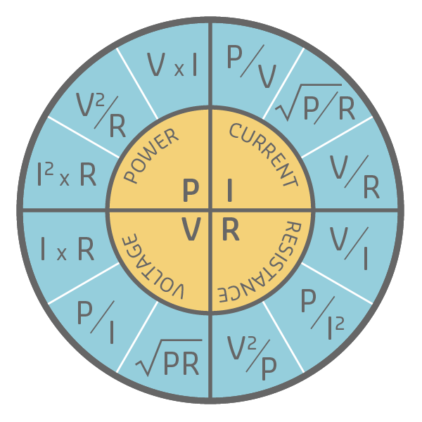
Ohm’s Wheel: Cover any variable to find multiple calculation formulas using known quantities.
Where: - I = Current (Amperes) - V = Voltage (Volts) - R = Resistance (Ohms)
Interpretation: - ⬆️ Voltage increases → ⬆️ Current increases (direct proportion) - ⬆️ Resistance increases → ⬇️ Current decreases (inverse proportion)
590.0.2 Derived Equations
From Ohm’s Law, we can derive:
\[V = I \times R\]
\[R = \frac{V}{I}\]
590.0.3 Ohm’s Wheel
The Ohm’s Wheel is a visual tool showing all relationships between V, I, R, and P (power):
{fig-alt=“Electrical circuit diagram showing”Ohm’s Wheel Cover unknown to find formula”, “V (Volts)”, “I (Amps)” including voltage, current, resistance relationships, component connections, and signal flow for understanding sensor power requirements and circuit fundamentals in IoT applications.”}
590.0.4 🧪 Interactive Lab: Ohm’s Law Circuit Demonstration
🎯 Interactive Challenges:
Try these experiments to deepen your understanding:
- Current Measurement Challenge: Calculate the current through the LED using Ohm’s Law, then verify with the ammeter
💡 Hint
Formula: I = V / R. With 5V supply and 220Ω resistor: I = (5V - 2V LED drop) / 220Ω ≈ 13.6 mA. Check if the simulation matches! - Resistor Selection Challenge: The LED datasheet says maximum current is 20 mA. Calculate the minimum resistor value needed
💡 Hint
Rearrange Ohm’s Law: R = V / I = (5V - 2V) / 0.02A = 150Ω. So use at least 150Ω to protect the LED. - Brightness Control Challenge: Try different resistor values (100Ω, 330Ω, 1kΩ). What happens to LED brightness and why?
💡 Hint
Higher resistance = lower current = dimmer LED. Verify by calculating current for each resistor value using Ohm’s Law. - Voltage Drop Challenge: Measure the voltage across the resistor and across the LED. Do they sum to 5V? Why?
💡 Hint
This demonstrates Kirchhoff’s Voltage Law (KVL): In any closed loop, voltages must sum to zero. V_supply = V_resistor + V_LED.
📊 What’s happening: - The 5V power supply provides electrical pressure - The 220Ω resistor limits current flow (Ohm’s Law: I = V/R) - The LED converts electrical energy to light (typical forward voltage ~2V) - Without the resistor, excessive current would destroy the LED - This is the fundamental circuit pattern for all LED indicators in IoT devices
Real-World Applications: - Every status LED on IoT devices uses this exact circuit - Raspberry Pi GPIO pins can only supply 16 mA safely—Ohm’s Law helps you calculate the right resistor - Smart home light dimmers use variable resistance (or PWM) to control brightness
590.1 Electronic Components
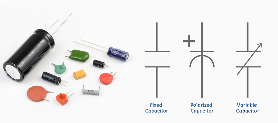
590.1.1 Capacitors
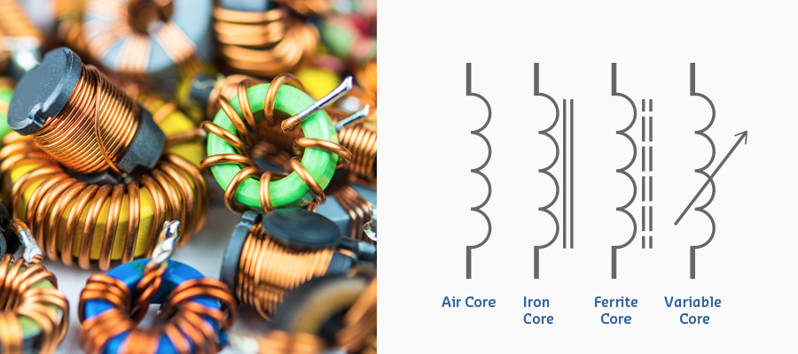
590.1.2 Inductors
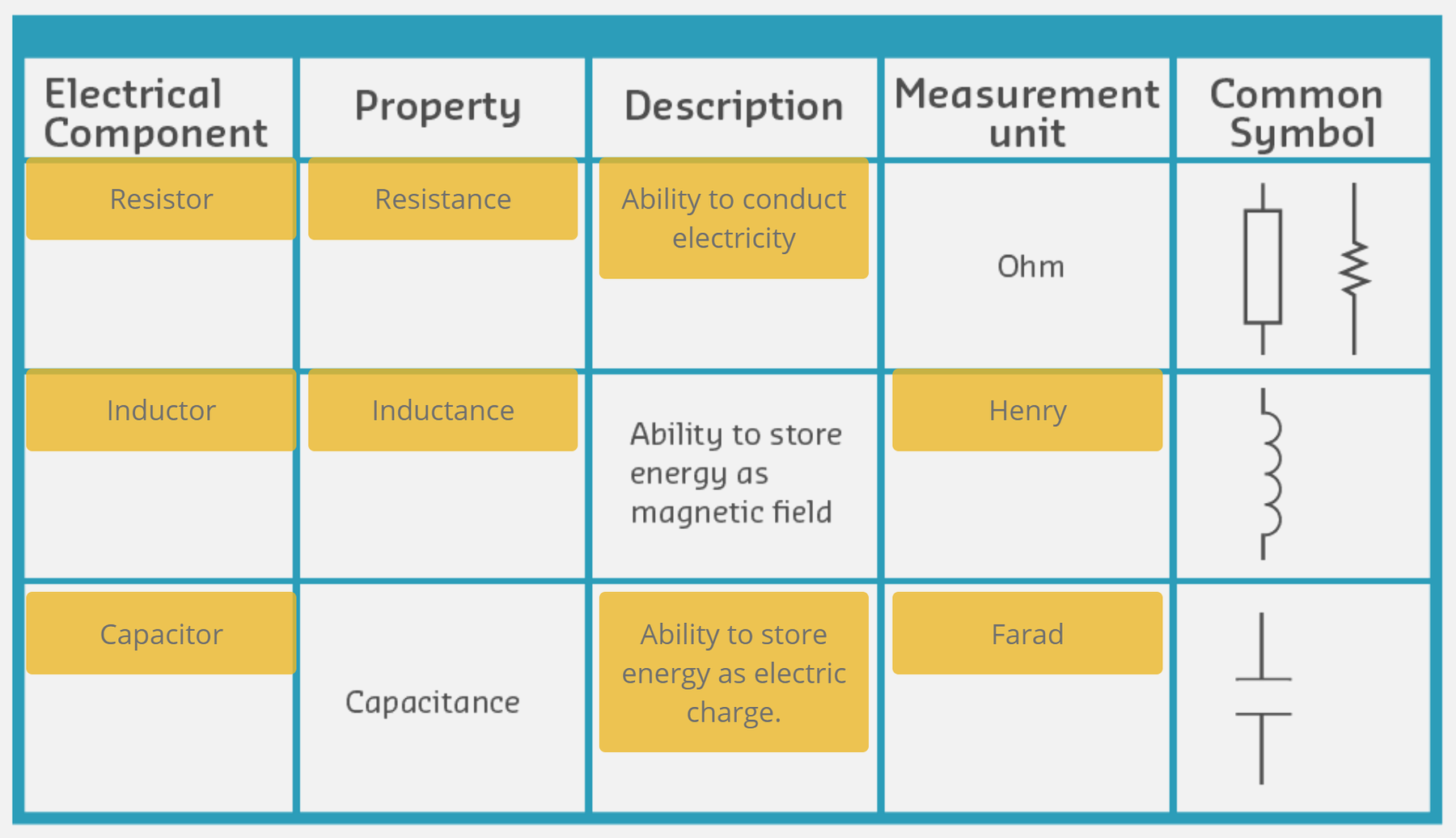
590.1.3 Component Comparison
590.2 Ohm’s Law: Complete Reference
The Ohm’s Wheel provides all 12 possible formulas for calculating voltage (V), current (I), resistance (R), and power (P) when any two values are known. This is the most comprehensive reference you’ll need for electrical calculations in IoT systems.
590.2.1 The Complete Formula Table
All 12 Formula Derivations:
| Known Values | Find V | Find I | Find R | Find P |
|---|---|---|---|---|
| V, I | - | - | V/I | V×I |
| V, R | - | V/R | - | V²/R |
| V, P | - | P/V | V²/P | - |
| I, R | I×R | - | - | I²×R |
| I, P | P/I | - | P/I² | - |
| R, P | √(P×R) | √(P/R) | - | - |
Tip📖 How to Use the Ohm’s Wheel
Step 1: Identify which two values you know (e.g., voltage and resistance)
Step 2: Locate the quadrant for the value you want to find (e.g., current)
Step 3: “Cover” the unknown value on the wheel—the remaining symbols show the formula
Example: To find current (I) when you know voltage (V) and resistance (R): - Cover I in the wheel - You see V/R - Formula: I = V/R
590.2.2 Worked Examples with Real IoT Applications
590.2.3 Quick Reference: Common IoT Component Calculations
Tip📊 Typical Values for IoT Devices
| Component | Typical Voltage | Typical Current | Power | Notes |
|---|---|---|---|---|
| ESP32 (Wi-Fi active) | 3.3V | 160-260 mA | 0.5-0.9W | Peaks at 500mA during TX |
| Arduino Uno | 5V | 50 mA (idle) | 0.25W | Excludes external peripherals |
| Raspberry Pi 4 | 5V | 600 mA (idle) - 1.2A (load) | 3-6W | Requires 3A rated supply |
| Status LED (red) | 2V (forward drop) | 10-20 mA | 0.02-0.04W | With current-limiting resistor |
| DHT22 (temp/humidity) | 3.3-5V | 1-2.5 mA | 0.003-0.0125W | During measurement |
| Servo motor (SG90) | 5V | 100-250 mA (idle) - 1A (stall) | 0.5-5W | Stall current can damage MCU pins |
| Relay module (5V) | 5V (coil) | 70-80 mA | 0.35-0.4W | Contact rating separate (10A/250VAC typical) |
| GSM module (SIM800) | 3.7-4.2V (LiPo) | 300 mA (idle) - 2A (TX burst) | 1.1-8.4W | Use dedicated power supply, not MCU |
Formula to remember: - LED resistor calculation: R = (V_supply - V_LED) / I_LED - Example: 5V supply, red LED (2V drop), 20mA → R = (5V - 2V) / 0.02A = 150Ω (use 220Ω for safety margin)
590.2.4 Understanding Check
Warning🎯 Application Problem: Smart Garden Irrigation Pump
You’re designing a solar-powered smart irrigation system for a community garden IoT project.
System Specifications: - Water pump: 12V DC, rated 40W - Solar panel: 18V (peak), 5A (peak) - Battery: 12V, 20Ah LiFePO4 - Charge controller: 12V, 10A PWM
Questions:
- What is the pump’s current draw at rated power?
- What is the pump motor’s resistance?
- How long can the pump run on a full battery before requiring recharge?
- The solar panel is under partial cloud cover, producing 12V at 3A. Can it run the pump AND charge the battery simultaneously?
- What fuse rating should protect the pump circuit?
💡 Solution & Analysis
1. Pump current draw:
From Ohm’s Wheel (P and V known, find I):
\[I = \frac{P}{V} = \frac{40W}{12V} = 3.33A\]
Answer: The pump draws 3.33A at rated power.
2. Pump motor resistance:
From Ohm’s Wheel (P and V known, find R):
\[R = \frac{V^2}{P} = \frac{(12V)^2}{40W} = \frac{144}{40} = 3.6Ω\]
Verification using I and V:
\[R = \frac{V}{I} = \frac{12V}{3.33A} = 3.6Ω\] ✓
Answer: Motor resistance is 3.6Ω.
3. Battery runtime:
Battery capacity: 20Ah at 12V
Runtime formula: \[t = \frac{\text{Battery Capacity (Ah)}}{\text{Current Draw (A)}} = \frac{20Ah}{3.33A} = 6.0 \text{ hours}\]
Practical adjustment: LiFePO4 batteries should not be discharged below 20% SoC for longevity.
Usable capacity: 20Ah × 0.8 = 16Ah
Practical runtime: \[t_{practical} = \frac{16Ah}{3.33A} = 4.8 \text{ hours}\]
Answer: 6 hours theoretical, 4.8 hours practical (with 20% reserve).
4. Simultaneous pump operation and charging?
Solar panel output: - Voltage: 12V (reduced from 18V peak due to clouds) - Current: 3A - Power: P = V × I = 12V × 3A = 36W
Pump requirement: - Power: 40W - Current: 3.33A
Analysis: - Solar provides: 36W - Pump requires: 40W - Deficit: 40W - 36W = 4W (must come from battery)
Answer: No, the solar panel cannot run the pump AND charge the battery. In fact, the battery must supplement the solar panel by 4W (0.33A) to keep the pump running.
Current flow: - Solar contribution: 3A - Battery supplement: 3.33A - 3A = 0.33A (discharging) - Net battery current: -0.33A (negative = discharging)
System behavior: The charge controller will draw 0.33A from the battery to make up the 4W shortfall.
5. Fuse rating for pump circuit:
Fuse selection criteria: 1. Protect against sustained overcurrent 2. Tolerate motor inrush (3-5× running current for 100-200ms)
Running current: 3.33A
Inrush current estimate: 3.33A × 4 = 13.3A (typical for DC motors)
Fuse sizing rule: 125% of continuous current (NEC guideline)
\[I_{fuse} = 3.33A \times 1.25 = 4.16A\]
Standard fuse ratings: 1A, 2A, 3A, 5A, 7A, 10A…
Selection: - 5A slow-blow fuse: Adequate for 3.33A continuous, tolerates 13.3A inrush ✓ Recommended - 7A slow-blow fuse: More margin, better for aging motors ✓ Alternative - 3A fuse: Too small, will blow on startup ✗
Answer: Use 5A slow-blow (T) fuse (minimum) or 7A slow-blow (recommended for safety margin).
System Design Recommendations:
- Solar panel sizing: For reliable operation without battery supplement:
- Required: 40W pump + 10W charging reserve = 50W minimum
- Recommended: 60-80W panel to handle efficiency losses (charge controller ~85% efficient)
- Battery protection:
- Add low-voltage disconnect (LVD) at 11V (or charge controller built-in LVD)
- Prevents over-discharge below 20% SoC
- Monitoring:
- INA219 sensor to measure solar panel voltage/current
- INA219 sensor to measure battery voltage/current
- ESP32 to log data and trigger alerts
- Energy optimization:
- Run pump only when solar produces >3.33A (sunlight sufficient)
- Schedule watering for peak sun hours (10 AM - 2 PM)
- Use soil moisture sensor to avoid unnecessary watering
590.2.5 IoT-Specific Applications and Calculations
590.2.6 Common Mistakes to Avoid
See Electricity Pitfalls for detailed coverage of common mistakes when working with electrical circuits.