%% fig-alt: "Water-electricity analogy diagram comparing water pressure to voltage, water flow to current, and pipe restriction to resistance"
%%{init: {'theme': 'base', 'themeVariables': {'primaryColor': '#2C3E50', 'primaryTextColor': '#fff', 'primaryBorderColor': '#16A085', 'lineColor': '#E67E22', 'secondaryColor': '#16A085', 'tertiaryColor': '#f4f4f4', 'clusterBkg': '#f9f9f9', 'clusterBorder': '#2C3E50', 'fontSize': '16px'}}}%%
graph LR
    subgraph Water["Water System"]
        A["Water Tank<br/>(Pressure)"] -->|Flow Rate| B["Narrow Pipe<br/>(Restriction)"]
        B --> C["Water Output"]
    end

    subgraph Electrical["Electrical System"]
        D["Battery<br/>(Voltage)"] -->|Current| E["Resistor<br/>(Resistance)"]
        E --> F["LED Output"]
    end

    style Water fill:#E3F2FD,stroke:#2C3E50,stroke-width:2px
    style Electrical fill:#E8F5E9,stroke:#2C3E50,stroke-width:2px
    style A fill:#16A085,stroke:#2C3E50,stroke-width:2px,color:#fff
    style D fill:#16A085,stroke:#2C3E50,stroke-width:2px,color:#fff
    style B fill:#E67E22,stroke:#2C3E50,stroke-width:2px,color:#fff
    style E fill:#E67E22,stroke:#2C3E50,stroke-width:2px,color:#fff
589 Electricity Fundamentals: Introduction
589.1 Learning Objectives
By the end of this section, you will be able to:
- Explain Electrical Basics: Understand current, voltage, and resistance
- Apply Ohm’s Law: Calculate voltage, current, resistance, and power
- Read Circuit Diagrams: Interpret schematic symbols and connections
- Understand Components: Differentiate between resistors, capacitors, and inductors
- Design Simple Circuits: Apply electrical principles to IoT hardware
589.2 Prerequisites
Before diving into this chapter, you should be familiar with:
- Basic Physics Concepts: Understanding atoms, electrons, and the concept of electric charge is helpful for grasping how electricity works at the fundamental level
- Basic Mathematics: Familiarity with algebra and working with equations (solving for variables) is essential for applying Ohm’s Law and power calculations
- IoT Reference Models: Basic awareness of IoT system architecture helps you understand where electrical principles apply in the hardware and device layer
589.3 For Kids: Electricity is Like Magic Water!
TipExplain Like I’m 5: What is Electricity?
Imagine tiny invisible water drops flowing through wires!
589.3.1 The Magic River Inside Wires
Electricity is like a river of teeny-tiny invisible drops called electrons. They flow through wires like water flows through pipes!
Here’s a fun way to understand it:
| Water World | Electricity World |
|---|---|
| Water in a tank | Batteries or power outlets |
| Water pipes | Wires |
| Water pump pushing hard | Voltage (how hard electrons push) |
| How much water flows | Current (how many electrons flow) |
| A narrow part of the pipe | Resistance (makes it harder to flow) |
589.3.2 A Story About Light Bulb Village
Once upon a time, there was a village called Light Bulb Village. The villagers needed energy to glow! There was a magical mountain called Battery Mountain that pushed tiny glowing particles called electrons down through wire rivers to the village.
When Battery Mountain pushed really hard (high voltage), lots of electrons flowed and the light bulbs glowed super bright! When it pushed gently (low voltage), fewer electrons flowed and the bulbs were dimmer.
Some wire rivers were wide and smooth - electrons loved flowing through those! But some were narrow and bumpy (high resistance) - electrons had a harder time getting through.
589.3.3 Try This at Home!
Make a “Circuit” With Your Friends: 1. Stand in a circle holding hands 2. One person is the “Battery” - they squeeze the hand of the person next to them 3. That person passes the squeeze to the next person 4. The squeeze goes around the circle and back to the battery!
That’s how electricity works! The squeeze is like voltage, and it flows all the way around (a circle = a circuit).
589.3.4 Why Do IoT Devices Need Electricity?
Every smart device needs electricity to: - Think (the brain chip needs power) - Talk (sending messages uses energy) - Feel (sensors need a tiny bit of power) - Remember (saving information takes power)
That’s why batteries are so important for sensors that aren’t plugged in!
589.3.5 Key Words for Kids
| Word | What It Means |
|---|---|
| Electricity | Invisible energy that flows through wires |
| Electron | A teeny-tiny particle that carries electricity |
| Battery | A container that stores electrical energy |
| Wire | A path for electricity to flow through |
| Circuit | A complete loop that electricity can flow around |
| Voltage | How hard electricity is pushed (like water pressure) |
589.3.6 Fun Fact!
Did you know? A single AA battery pushes electricity with 1.5 volts - just enough to make a small LED glow! But the outlet in your wall pushes with 120 volts (in the US) or 230 volts (in Europe) - that’s why we never touch outlets!
TipFor Kids: Meet the Sensor Squad! 🌟
Electricity is like a river of invisible energy that flows through wires to power everything!
589.3.7 The Sensor Squad Adventure: The Magical Power River
One sunny morning, Sammy the Sensor woke up feeling very weak. “I can’t sense anything today!” Sammy said sadly. Bella the Battery hurried over with her shiny silver jacket. “Don’t worry, Sammy! I’ll share my magical energy river with you!”
Bella explained how she stores tiny invisible workers called electrons inside her. “When I connect to the wire, the electrons flow like a river from me, through the wire, through you, and back to me in a big circle!” Max the Microcontroller drew a picture: “See? The electrons go around and around in a loop - that’s called a circuit! If the circle is broken anywhere, the river stops flowing.”
Lila the LED started glowing brightly. “The electrons flowing through me make me light up! But if too many come at once, I get too hot!” Bella nodded wisely. “That’s why we use resistors - they’re like narrow parts of the pipe that slow down the electron river so nobody gets hurt.” Thanks to Bella’s energy river, Sammy could sense temperature again, Lila could glow safely, and Max could think and make decisions. The Sensor Squad was powered up and ready for action!
589.3.8 Key Words for Kids
| Word | What It Means |
|---|---|
| Electricity | Invisible energy that flows through wires like water through pipes |
| Battery | A container that stores electrical energy until you need it |
| Circuit | A complete loop path for electricity to flow around |
| Voltage | How hard the electricity is being pushed (like water pressure) |
| Current | How much electricity is flowing (like how much water comes out) |
| Resistor | A part that slows down electricity so things don’t get too hot |
589.3.9 Try This at Home!
Build a Human Circuit!
- Gather 4-6 friends or family members
- Stand in a circle and hold hands
- One person is the “Battery” - they squeeze the hand of the person next to them
- Each person passes the squeeze to the next person around the circle
- The squeeze travels all the way around back to the battery!
What you learned: The squeeze is like voltage (the push), and it travels around the circuit (the circle of people). If anyone lets go of hands, the circuit is broken and the squeeze can’t travel anymore - just like electricity!
589.4 🌱 Getting Started (For Beginners)
589.4.1 Understanding Electricity: The Water Analogy
The easiest way to understand electricity is to think of it like water flowing through pipes:
NoteAlternative View: IoT Device Power Budget Decision Tree
This decision tree variant helps you calculate and manage power consumption for battery-powered IoT devices - a critical practical application of electrical concepts.
%%{init: {'theme': 'base', 'themeVariables': {'primaryColor': '#2C3E50', 'primaryTextColor': '#fff', 'primaryBorderColor': '#16A085', 'lineColor': '#16A085', 'secondaryColor': '#E67E22', 'tertiaryColor': '#ECF0F1', 'fontSize': '11px'}}}%%
flowchart TD
    START([Battery Capacity<br/>e.g., 1000mAh]) --> Q1{Sleep Current?}

    Q1 -->|"<10µA (good)"| SLEEP_LOW["Deep Sleep Mode<br/>Mostly sleeping"]
    Q1 -->|">100µA (bad)"| SLEEP_HIGH["Light Sleep<br/>Battery drains faster"]

    SLEEP_LOW --> Q2{Active Current?}
    SLEEP_HIGH --> Q2

    Q2 -->|"ESP32: ~80mA"| ACTIVE["Active Time<br/>per cycle"]
    Q2 -->|"Wi-Fi TX: ~200mA"| ACTIVE

    ACTIVE --> CALC["Calculate:<br/>Avg = Sleep×T_sleep + Active×T_active"]

    CALC --> LIFE["Battery Life =<br/>Capacity ÷ Avg Current"]

    LIFE --> EX1["Example: 1000mAh<br/>10µA sleep, 80mA×1s/hour<br/>≈ 3.5 years!"]
    LIFE --> EX2["Example: 1000mAh<br/>100µA sleep, 200mA×10s/min<br/>≈ 5 days"]

    style START fill:#16A085,stroke:#2C3E50,color:#fff
    style SLEEP_LOW fill:#16A085,stroke:#2C3E50,color:#fff
    style SLEEP_HIGH fill:#E67E22,stroke:#2C3E50,color:#fff
    style CALC fill:#2C3E50,stroke:#16A085,color:#fff
    style EX1 fill:#16A085,stroke:#2C3E50,color:#fff
    style EX2 fill:#E67E22,stroke:#2C3E50,color:#fff
%%{init: {'theme': 'base', 'themeVariables': {'primaryColor': '#2C3E50', 'primaryTextColor': '#fff', 'primaryBorderColor': '#16A085', 'lineColor': '#16A085', 'secondaryColor': '#E67E22', 'tertiaryColor': '#f4f4f4', 'fontSize': '12px'}}}%%
flowchart TB
    subgraph cause["CAUSE (Energy Source)"]
        V["VOLTAGE (V)<br/>Electrical Pressure<br/>Volts"]
    end

    subgraph resistance["OPPOSITION"]
        R["RESISTANCE (R)<br/>Restricts Flow<br/>Ohms (Ω)"]
    end

    subgraph effect["EFFECT (What Flows)"]
        I["CURRENT (I)<br/>Electron Flow<br/>Amps (A)"]
    end

    subgraph result["RESULT (Work Done)"]
        P["POWER (P)<br/>Energy Used<br/>Watts (W)"]
    end

    V -->|"pushes against"| R
    R -->|"limits"| I
    V -->|"V × I ="| P
    I -->|"I × R = V"| V

    style cause fill:#E8F5E9,stroke:#16A085
    style resistance fill:#FFF3E0,stroke:#E67E22
    style effect fill:#E3F2FD,stroke:#2C3E50
    style result fill:#FCE4EC,stroke:#9B59B6
{fig-alt=“Electrical circuit diagram showing”Water System”, “Water Tank (Pressure)”, “Narrow Pipe (Restriction)” including voltage, current, resistance relationships, component connections, and signal flow for understanding sensor power requirements and circuit fundamentals in IoT applications.”}
| Water Concept | Electrical Equivalent | Unit | What It Means |
|---|---|---|---|
| Water pressure | Voltage (V) | Volts | How hard electrons are “pushed” |
| Water flow rate | Current (I) | Amps | How many electrons flow per second |
| Pipe narrowness | Resistance (R) | Ohms | How much the flow is restricted |
589.4.2 The Three Key Relationships
1. Higher pressure → More flow (Higher voltage → More current)
Low Voltage (3.3V)     High Voltage (12V)
    ─ ─ ─ → →           ═══════════→ → →
    Dim LED              Bright LED
2. Narrower pipe → Less flow (Higher resistance → Less current)
Low Resistance (100Ω)    High Resistance (10kΩ)
    ══════════→ → →        ─ ─ ─ →
    Bright LED             Dim LED
3. Ohm’s Law: V = I × R (The fundamental equation!)
%% fig-alt: "Ohm's Law triangle showing the relationship between Voltage (V), Current (I), and Resistance (R) with formulas V=I×R, I=V/R, and R=V/I"
%%{init: {'theme': 'base', 'themeVariables': {'primaryColor': '#2C3E50', 'primaryTextColor': '#fff', 'primaryBorderColor': '#16A085', 'lineColor': '#E67E22', 'secondaryColor': '#16A085', 'tertiaryColor': '#f4f4f4', 'fontSize': '18px'}}}%%
graph TD
    V["V<br/>Voltage (Volts)"]
    I["I<br/>Current (Amps)"]
    R["R<br/>Resistance (Ohms)"]

    V -->|"V = I × R"| IR["I × R"]
    I -->|"I = V / R"| VR["V / R"]
    R -->|"R = V / I"| VI["V / I"]

    style V fill:#16A085,stroke:#2C3E50,stroke-width:3px,color:#fff
    style I fill:#E67E22,stroke:#2C3E50,stroke-width:3px,color:#fff
    style R fill:#2C3E50,stroke:#16A085,stroke-width:3px,color:#fff
    style IR fill:#f4f4f4,stroke:#2C3E50,stroke-width:2px
    style VR fill:#f4f4f4,stroke:#2C3E50,stroke-width:2px
    style VI fill:#f4f4f4,stroke:#2C3E50,stroke-width:2px
{fig-alt=“Electrical circuit diagram showing”V Voltage (Volts)“,”I Current (Amps)“,”R Resistance (Ohms)” including voltage, current, resistance relationships, component connections, and signal flow for understanding sensor power requirements and circuit fundamentals in IoT applications.”}
589.4.3 Real-World IoT Example: LED Circuit
You want to light an LED with an Arduino (5V output). LEDs typically need 2V and 20mA.
%% fig-alt: "LED circuit diagram showing 5V Arduino output, current-limiting resistor calculation, and LED with voltage drop, demonstrating practical application of Ohm's Law"
%%{init: {'theme': 'base', 'themeVariables': {'primaryColor': '#2C3E50', 'primaryTextColor': '#fff', 'primaryBorderColor': '#16A085', 'lineColor': '#E67E22', 'secondaryColor': '#16A085', 'tertiaryColor': '#f4f4f4', 'fontSize': '16px'}}}%%
graph LR
    A["Arduino Pin<br/>5V"] -->|Current: 20mA| B["Resistor<br/>150Ω"]
    B --> C["LED<br/>Forward: 2V"]
    C --> D["Ground<br/>0V"]

    E["Calculation:<br/>R = (Vsupply - VLED) / I<br/>R = (5V - 2V) / 0.02A<br/>R = 150Ω"]

    style A fill:#16A085,stroke:#2C3E50,stroke-width:2px,color:#fff
    style B fill:#E67E22,stroke:#2C3E50,stroke-width:2px,color:#fff
    style C fill:#2C3E50,stroke:#16A085,stroke-width:2px,color:#fff
    style D fill:#7F8C8D,stroke:#2C3E50,stroke-width:2px,color:#fff
    style E fill:#FFF9C4,stroke:#E67E22,stroke-width:2px,color:#000
{fig-alt=“Electrical circuit diagram showing”Arduino Pin 5V”, “Resistor 150Ω”, “LED Forward: 2V” including voltage, current, resistance relationships, component connections, and signal flow for understanding sensor power requirements and circuit fundamentals in IoT applications.”}
589.4.4 Self-Check: Understanding the Basics
Before continuing, make sure you can answer:
- If voltage increases, what happens to current? → Current increases (assuming resistance stays same)
- What does resistance do? → Limits/reduces current flow
- How do you calculate power? → P = V × I (Watts = Volts × Amps)
- Why do we need resistors with LEDs? → To limit current and prevent burning out the LED
ImportantWhy Electricity Matters for IoT
Every IoT device runs on electricity. Sensors, microcontrollers, communication modules, actuators - all require electrical power and understanding electrical principles. Without electricity, there is no IoT.
NoteKey Concepts
- Current (I): Flow of electric charge measured in Amperes (A); the rate at which electrons move through a conductor
- Voltage (V): Electric potential difference measured in Volts (V); the “pressure” that pushes electrons through a circuit
- Resistance (R): Opposition to current flow measured in Ohms (Ω); determines how much current flows for a given voltage
- Ohm’s Law: Fundamental relationship V = I × R relating voltage, current, and resistance in electrical circuits
- Power (P): Rate of energy consumption measured in Watts (W); calculated as P = V × I
- Series vs Parallel: Circuit configurations affecting total resistance and voltage/current distribution
NoteKey Takeaway
In one sentence: V = IR and P = VI are the two equations that govern every electrical circuit–master them and you can design any IoT power system.
Remember this rule: Current kills, not voltage alone–always calculate both voltage AND current capacity when assessing circuit safety and component ratings.
589.5 What is Electricity?
Electricity is a form of energy - specifically, the energy associated with the movement of electrons between atoms.
589.5.1 Types of Energy
Before diving into electricity, let’s understand the broader context. Energy can be classified into six types:
| Type | Examples | IoT Relevance |
|---|---|---|
| Mechanical | Windmills, gears, motors | Actuators, moving parts |
| Chemical | Batteries, fuel cells | Power sources |
| Electrical | Circuits, sensors, microcontrollers | Core of all IoT devices |
| Radiant | Solar panels, LEDs, lasers | Energy harvesting, displays |
| Nuclear | Not typically used in IoT | - |
| Sound | Acoustic sensors, speakers | Audio IoT applications |
Key Principle: Energy cannot be created or destroyed, only transformed. IoT devices constantly transform energy from one form to another (chemical → electrical → light/motion/data).
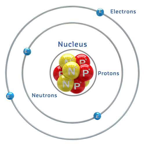
589.6 Atoms and Electrons
Understanding electricity requires understanding atomic structure.
%% fig-alt: "Atomic structure diagram showing nucleus with protons and neutrons at center, surrounded by electron shells with orbiting electrons"
%%{init: {'theme': 'base', 'themeVariables': {'primaryColor': '#2C3E50', 'primaryTextColor': '#fff', 'primaryBorderColor': '#16A085', 'lineColor': '#E67E22', 'secondaryColor': '#16A085', 'tertiaryColor': '#f4f4f4', 'fontSize': '16px'}}}%%
graph TB
    subgraph Nucleus["Nucleus (Center)"]
        P["⊕ Protons<br/>(Positive +)"]
        N["◯ Neutrons<br/>(Neutral)"]
    end

    subgraph Shell1["Inner Electron Shell"]
        E1["⊖ Electron"]
        E2["⊖ Electron"]
    end

    subgraph Shell2["Outer Electron Shell"]
        E3["⊖ Electron"]
        E4["⊖ Electron"]
        E5["⊖ Electron"]
    end

    Nucleus -.->|"10,000× smaller"| Shell1
    Shell1 -.-> Shell2

    style Nucleus fill:#E67E22,stroke:#2C3E50,stroke-width:3px
    style Shell1 fill:#E8F5E9,stroke:#16A085,stroke-width:2px,stroke-dasharray: 5 5
    style Shell2 fill:#E3F2FD,stroke:#16A085,stroke-width:2px,stroke-dasharray: 5 5
    style P fill:#E74C3C,stroke:#2C3E50,stroke-width:2px,color:#fff
    style N fill:#7F8C8D,stroke:#2C3E50,stroke-width:2px,color:#fff
    style E1 fill:#2C3E50,stroke:#16A085,stroke-width:2px,color:#fff
    style E2 fill:#2C3E50,stroke:#16A085,stroke-width:2px,color:#fff
    style E3 fill:#2C3E50,stroke:#16A085,stroke-width:2px,color:#fff
    style E4 fill:#2C3E50,stroke:#16A085,stroke-width:2px,color:#fff
    style E5 fill:#2C3E50,stroke:#16A085,stroke-width:2px,color:#fff
{fig-alt=“Electrical circuit diagram showing”Nucleus (Center)“,”⊕ Protons (Positive +)“,”◯ Neutrons (Neutral)” including voltage, current, resistance relationships, component connections, and signal flow for understanding sensor power requirements and circuit fundamentals in IoT applications.”}
Key Components: - Protons (+): Positively charged particles in the nucleus - Neutrons (neutral): Neutral particles in the nucleus - Electrons (-): Negatively charged particles orbiting the nucleus
The electron cloud occupies a volume 10,000× larger than the nucleus!
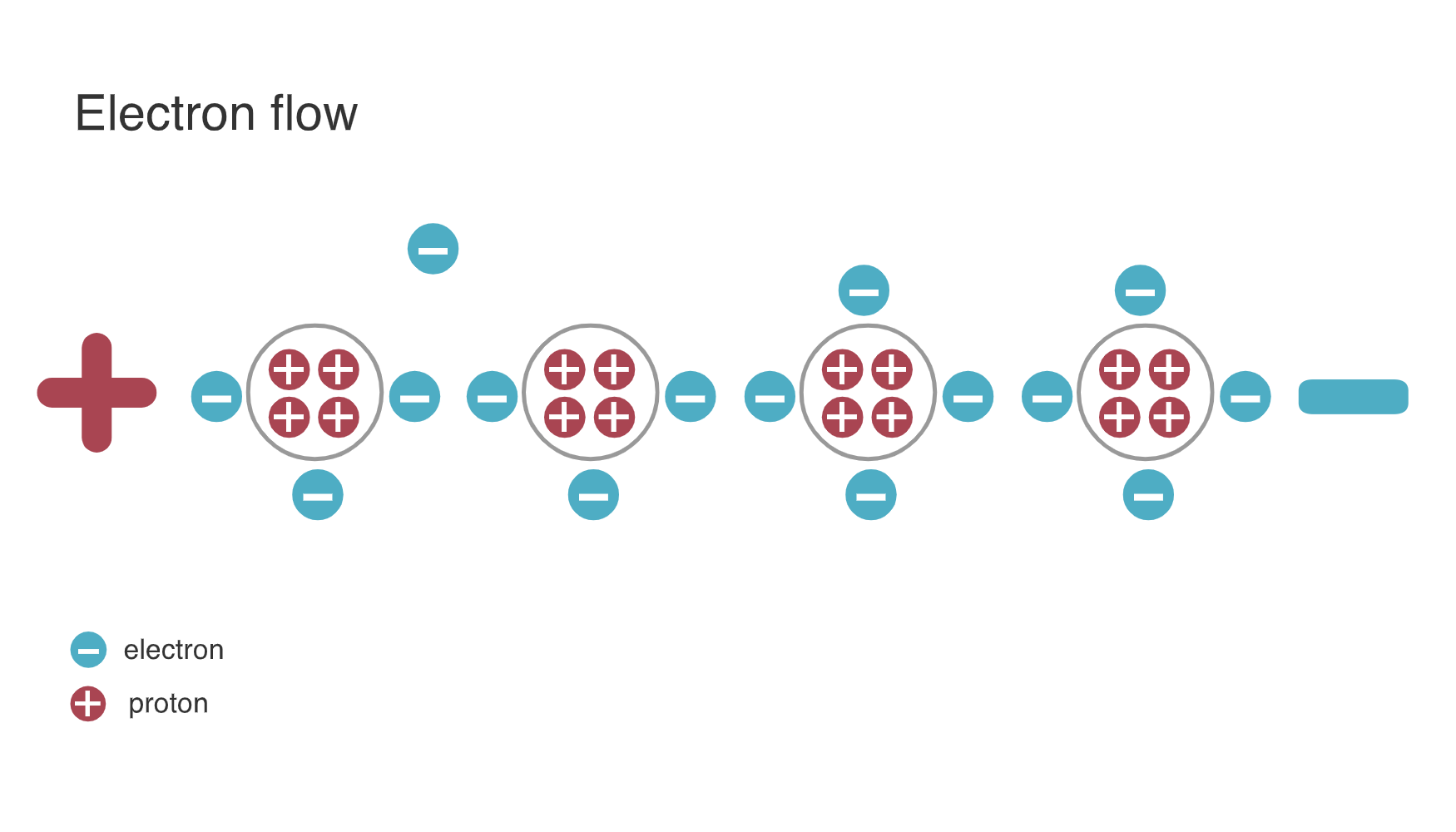
589.6.1 How Electricity Works
Electricity occurs when electrons jump from one atom to another.
%% fig-alt: "Electron flow diagram showing electrons moving from atom to atom through a conductor, creating electric current from negative to positive"
%%{init: {'theme': 'base', 'themeVariables': {'primaryColor': '#2C3E50', 'primaryTextColor': '#fff', 'primaryBorderColor': '#16A085', 'lineColor': '#E67E22', 'secondaryColor': '#16A085', 'tertiaryColor': '#f4f4f4', 'fontSize': '16px'}}}%%
graph LR
    A["Atom 1<br/>(Excess ⊖)"] -->|"⊖ jumps"| B["Atom 2"]
    B -->|"⊖ jumps"| C["Atom 3"]
    C -->|"⊖ jumps"| D["Atom 4<br/>(Deficit ⊖)"]

    E["Negative (-)<br/>Excess Electrons"] -.->|"Electrons flow this way"| F["Positive (+)<br/>Deficit Electrons"]

    style A fill:#2C3E50,stroke:#16A085,stroke-width:2px,color:#fff
    style B fill:#7F8C8D,stroke:#2C3E50,stroke-width:2px,color:#fff
    style C fill:#7F8C8D,stroke:#2C3E50,stroke-width:2px,color:#fff
    style D fill:#E67E22,stroke:#2C3E50,stroke-width:2px,color:#fff
    style E fill:#2C3E50,stroke:#16A085,stroke-width:2px,color:#fff
    style F fill:#E67E22,stroke:#2C3E50,stroke-width:2px,color:#fff
{fig-alt=“Electrical circuit diagram showing”Atom 1 (Excess ⊖)“,”Atom 2”, “Atom 3” including voltage, current, resistance relationships, component connections, and signal flow for understanding sensor power requirements and circuit fundamentals in IoT applications.”}
Electrical Charge: - Negative (-): Material with excess electrons - Positive (+): Material with deficit of electrons
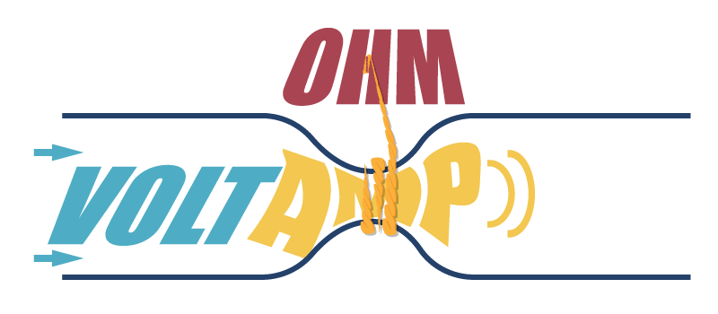
NoteOriginal Source Figure: Electron Flow (Alternative View)


Source: CP IoT System Design Guide, Chapter 3 - Sensing and Actuation
TipAI-Generated Figure: Electron Flow (Artistic Rendering)

Electron drift creates current: Free electrons move through the conductor’s atomic lattice from negative to positive terminal.
- Electrical Potential: The difference in charge between two points
Nature seeks equilibrium: Electrons flow from negative to positive, balancing the charge difference.
NoteImportant Convention
Physically: Electrons flow from negative (-) to positive (+) By Convention: We analyze circuits as if current flows from positive (+) to negative (-)
This historical convention is used in all circuit analysis and design.
589.7 The Big Three: Current, Voltage, Resistance
589.7.1 Electric Current (I)
Definition: The flow of electrons between atoms, measured in Amperes (A).
- 1 Ampere = 1 Coulomb of charge flowing per second
- 1 Coulomb = 6.24 × 10¹⁸ electrons (6.24 quintillion!)
Water Analogy: Think of current like water flowing through a pipe - the amount of water flowing per second.
589.7.2 Voltage (V)
Definition: The difference in electric charge between two points, measured in Volts (V).
- Greater voltage = greater “pressure” pushing electrons
- Creates the “force” that drives current flow
Water Analogy: Think of voltage like water pressure - the higher the pressure difference, the more water flows.
589.7.3 Resistance (R)
Definition: The opposition to current flow in a material, measured in Ohms (Ω).
- Good conductors (copper, gold): Low resistance
- Insulators (rubber, plastic): High resistance
- Resistors: Components specifically designed to provide resistance
Water Analogy: Think of resistance like pipe diameter - narrow pipes resist flow more than wide pipes.
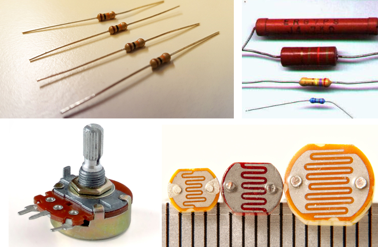
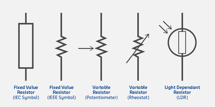
589.8 Resistors
Resistors are passive components that control current flow in circuits.

Understanding Ohm’s Law (V = I x R) is fundamental to designing every IoT circuit. From calculating LED resistor values to sizing pull-ups for I2C buses, these calculations determine whether your circuits work reliably or fail in the field.
Common Resistor Types:
| Type | Application | Range |
|---|---|---|
| Carbon Film | General purpose | 1Ω - 10MΩ |
| Metal Film | Precision circuits | 0.1Ω - 1MΩ |
| Wire Wound | High power | 0.01Ω - 100kΩ |
| Surface Mount (SMD) | Compact PCBs | 0.1Ω - 10MΩ |
| Variable (Potentiometer) | Adjustable resistance | 100Ω - 1MΩ |
Circuit Symbols:
%% fig-alt: "Resistor types comparison showing fixed, variable, and specialized resistors with their applications and typical values"
%%{init: {'theme': 'base', 'themeVariables': {'primaryColor': '#2C3E50', 'primaryTextColor': '#fff', 'primaryBorderColor': '#16A085', 'lineColor': '#E67E22', 'secondaryColor': '#16A085', 'tertiaryColor': '#f4f4f4', 'fontSize': '15px'}}}%%
graph TB
    Resistors["Resistor Types"]

    Resistors --> Fixed["Fixed Resistors"]
    Resistors --> Variable["Variable Resistors"]
    Resistors --> Special["Specialized Resistors"]

    Fixed --> F1["Carbon Film<br/>General purpose<br/>1Ω - 10MΩ"]
    Fixed --> F2["Metal Film<br/>Precision circuits<br/>0.1Ω - 1MΩ"]
    Fixed --> F3["SMD<br/>Compact PCBs<br/>0.1Ω - 10MΩ"]

    Variable --> V1["Potentiometer<br/>Adjustable<br/>100Ω - 1MΩ"]
    Variable --> V2["Trimmer<br/>One-time tuning<br/>10Ω - 100kΩ"]

    Special --> S1["Thermistor<br/>Temperature sensing<br/>1kΩ - 100kΩ"]
    Special --> S2["Photoresistor<br/>Light detection<br/>10Ω - 1MΩ"]

    style Resistors fill:#16A085,stroke:#2C3E50,stroke-width:3px,color:#fff
    style Fixed fill:#E67E22,stroke:#2C3E50,stroke-width:2px,color:#fff
    style Variable fill:#E67E22,stroke:#2C3E50,stroke-width:2px,color:#fff
    style Special fill:#E67E22,stroke:#2C3E50,stroke-width:2px,color:#fff
    style F1 fill:#f4f4f4,stroke:#2C3E50,stroke-width:2px
    style F2 fill:#f4f4f4,stroke:#2C3E50,stroke-width:2px
    style F3 fill:#f4f4f4,stroke:#2C3E50,stroke-width:2px
    style V1 fill:#f4f4f4,stroke:#2C3E50,stroke-width:2px
    style V2 fill:#f4f4f4,stroke:#2C3E50,stroke-width:2px
    style S1 fill:#f4f4f4,stroke:#2C3E50,stroke-width:2px
    style S2 fill:#f4f4f4,stroke:#2C3E50,stroke-width:2px
%%{init: {'theme': 'base', 'themeVariables': {'primaryColor': '#2C3E50', 'primaryTextColor': '#fff', 'primaryBorderColor': '#16A085', 'lineColor': '#16A085', 'secondaryColor': '#E67E22', 'tertiaryColor': '#f4f4f4', 'fontSize': '11px'}}}%%
flowchart LR
    subgraph protect["PROTECTION"]
        R1["LED Current Limit<br/>330Ω @ 10mA<br/>Prevents burnout"]
        R2["GPIO Protection<br/>10kΩ series<br/>Limits ESD damage"]
    end

    subgraph sense["SENSING"]
        R3["Thermistor<br/>10kΩ NTC<br/>Temp varies resistance"]
        R4["Photoresistor<br/>10kΩ-1MΩ<br/>Light varies resistance"]
        R5["Force Sensor<br/>1kΩ-100kΩ<br/>Pressure varies R"]
    end

    subgraph condition["SIGNAL CONDITIONING"]
        R6["Voltage Divider<br/>10k/10k = 50%<br/>Level shifting 5V→2.5V"]
        R7["Pull-up/down<br/>4.7kΩ-10kΩ<br/>Default logic state"]
    end

    subgraph adjust["CALIBRATION"]
        R8["Trimmer Pot<br/>10kΩ<br/>One-time tuning"]
        R9["Gain Adjust<br/>100kΩ pot<br/>Op-amp gain control"]
    end

    style protect fill:#FCE4EC,stroke:#E74C3C
    style sense fill:#E8F5E9,stroke:#16A085
    style condition fill:#E3F2FD,stroke:#2C3E50
    style adjust fill:#FFF3E0,stroke:#E67E22
{fig-alt=“Electrical circuit diagram showing”Resistor Types”, “Fixed Resistors”, “Variable Resistors” including voltage, current, resistance relationships, component connections, and signal flow for understanding sensor power requirements and circuit fundamentals in IoT applications.”}
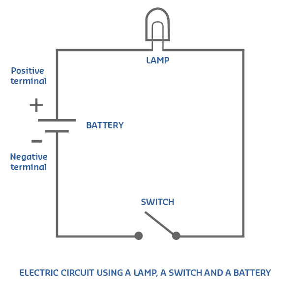
589.9 Circuit Diagrams
Circuit diagrams (schematics) are visual representations of electrical circuits using standardized symbols.
589.9.1 Basic Circuit Example: Light Switch
%% fig-alt: "Simple light switch circuit diagram showing battery, switch, and lamp in series, demonstrating open and closed circuit states"
%%{init: {'theme': 'base', 'themeVariables': {'primaryColor': '#2C3E50', 'primaryTextColor': '#fff', 'primaryBorderColor': '#16A085', 'lineColor': '#E67E22', 'secondaryColor': '#16A085', 'tertiaryColor': '#f4f4f4', 'fontSize': '16px'}}}%%
graph LR
    subgraph Open["Switch Open (OFF)"]
        B1["+ Battery -"] -.->|"No current"| S1["Switch<br/>(Open)"]
        S1 -.-> L1["Lamp<br/>(OFF)"]
        L1 -.-> B1
    end

    subgraph Closed["Switch Closed (ON)"]
        B2["+ Battery -"] -->|"Current flows"| S2["Switch<br/>(Closed)"]
        S2 --> L2["💡 Lamp<br/>(ON)"]
        L2 --> B2
    end

    style Open fill:#FFEBEE,stroke:#2C3E50,stroke-width:2px
    style Closed fill:#E8F5E9,stroke:#2C3E50,stroke-width:2px
    style B1 fill:#E67E22,stroke:#2C3E50,stroke-width:2px,color:#fff
    style B2 fill:#E67E22,stroke:#2C3E50,stroke-width:2px,color:#fff
    style S1 fill:#7F8C8D,stroke:#2C3E50,stroke-width:2px,color:#fff
    style S2 fill:#16A085,stroke:#2C3E50,stroke-width:2px,color:#fff
    style L1 fill:#f4f4f4,stroke:#2C3E50,stroke-width:2px
    style L2 fill:#16A085,stroke:#2C3E50,stroke-width:2px,color:#fff
{fig-alt=“Electrical circuit diagram showing”Switch Open (OFF)“,”+ Battery -“,”Switch (Open)” including voltage, current, resistance relationships, component connections, and signal flow for understanding sensor power requirements and circuit fundamentals in IoT applications.”}
How it works: - Switch Open: No path for electrons → Lamp OFF - Switch Closed: Complete circuit → Current flows → Lamp ON
Tip📹 Video: How to Read a Schematic
SparkFun Tutorial: How to Read a Schematic
Learn to interpret circuit diagrams, component symbols, and connections.
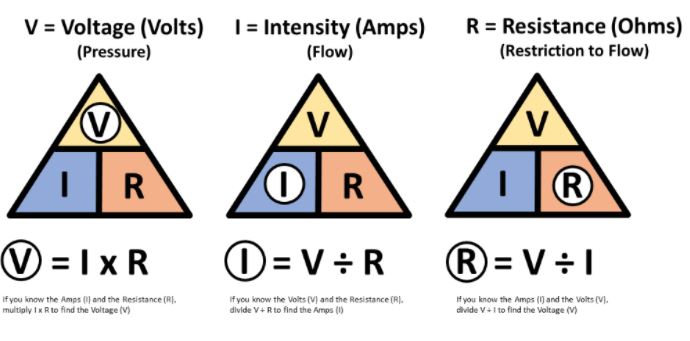
NoteOriginal Source Figure: Ohm’s Law (Alternative View)
Source: CP IoT System Design Guide, Chapter 3 - Sensing and Actuation
NoteOriginal Source Figure: Ohm’s Law Applications (Alternative View)
Source: CP IoT System Design Guide, Chapter 3 - Sensing and Actuation
TipAI-Generated Figure: Ohm’s Law (Artistic Rendering)

The Ohm’s Law triangle: Cover the unknown variable to reveal the formula using the other two.
TipAI-Generated Figure: Ohm’s Law Applications (Artistic Rendering)

Practical applications: From LED circuits to sensor power budgets, Ohm’s Law solves real IoT design challenges.