%%{init: {'theme': 'base', 'themeVariables': { 'primaryColor': '#2C3E50', 'primaryTextColor': '#fff', 'primaryBorderColor': '#1A252F', 'lineColor': '#2C3E50', 'secondaryColor': '#16A085', 'tertiaryColor': '#E67E22', 'noteTextColor': '#2C3E50', 'noteBkgColor': '#ECF0F1', 'textColor': '#2C3E50', 'fontSize': '16px'}}}%%
flowchart LR
    subgraph Input["Digital Input"]
        DI["Binary Value<br/>0-255<br/>Discrete"]
    end

    subgraph DAC["DAC Converter"]
        DEC["Decoder"]
        RES["Resistor<br/>Network"]
        AMP["Output<br/>Amplifier"]
    end

    subgraph Output["Analog Output"]
        AO["Voltage<br/>0-5V<br/>Continuous"]
    end

    DI --> DEC
    DEC --> RES
    RES --> AMP
    AMP --> AO

    VREF["Reference<br/>Voltage<br/>Vref"]
    VREF -.defines max.-> RES

    style Input fill:#2C3E50,stroke:#1A252F,color:#fff
    style DAC fill:#16A085,stroke:#138D75,color:#fff
    style Output fill:#E67E22,stroke:#D35400,color:#fff
    style DI fill:#ECF0F1,stroke:#2C3E50,color:#fff
    style DEC fill:#ECF0F1,stroke:#16A085,color:#2C3E50
    style RES fill:#ECF0F1,stroke:#16A085,color:#2C3E50
    style AMP fill:#ECF0F1,stroke:#16A085,color:#2C3E50
    style AO fill:#ECF0F1,stroke:#2C3E50,color:#2C3E50
    style VREF fill:#7F8C8D,stroke:#5D6D7E,color:#fff
603 DAC and PWM Output
603.1 Learning Objectives
By the end of this section, you will be able to:
- Explain DAC Operation: Understand how digital-to-analog converters work
- Apply DAC Formulas: Calculate output voltage from digital input
- Understand PWM: Use pulse width modulation as pseudo-analog output
- Design RC Filters: Convert PWM to smooth analog voltage
- Control Actuators: Interface motors, LEDs, and other analog loads
- Choose DAC vs PWM: Select appropriate output method for different applications
603.2 Prerequisites
Before diving into this chapter, you should be familiar with:
- ADC Fundamentals: Understanding ADC operation helps understand DAC as the inverse process
- Binary Fundamentals: Binary number systems and resolution
- Electricity Fundamentals: Understanding voltage, current, and basic circuits
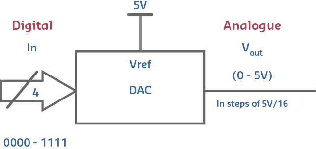
603.3 Digital-to-Analog Converters (DAC)
DAC = Device that converts digital numbers into analog voltage
603.3.1 DAC Formula
\[V_{out} = V_{ref} \times \frac{Digital\ Input}{2^n - 1}\]
Example (8-bit DAC, Vref = 5V):
| Digital Input | Calculation | Voltage Output |
|---|---|---|
| 0 | 5 x (0/255) | 0.00 V |
| 64 | 5 x (64/255) | 1.25 V |
| 128 | 5 x (128/255) | 2.51 V |
| 192 | 5 x (192/255) | 3.76 V |
| 255 | 5 x (255/255) | 5.00 V |
603.3.2 DAC Applications in IoT
| Application | Example | DAC Type |
|---|---|---|
| Audio Output | Music playback | 12-16 bit, 44.1 kHz |
| Motor Speed Control | PWM alternative | 8-10 bit |
| LED Brightness | Smooth dimming | 8-12 bit |
| Analog Sensor Simulation | Testing | 12 bit |
| Waveform Generation | Signal generator | 12-16 bit |
603.4 DAC Circuit Architecture
TipAI-Generated Figure: DAC Circuit Design (Artistic Rendering)

R-2R ladder DAC architecture converts binary values to proportional analog voltages through weighted current summation.
R-2R Ladder Network: - Uses only two resistor values (R and 2R) - Each bit contributes proportional current - Binary-weighted output voltage - Low cost, moderate accuracy
603.5 Quantization Error in DAC
Problem: DAC output is not truly analog - it’s discrete steps
Quantization Error = Difference between ideal smooth output and actual stepped output
Reducing Error: 1. Increase bit depth (8-bit → 12-bit → 16-bit) 2. Increase update rate (faster DAC updates) 3. Add filtering (low-pass filter smooths steps)
603.6 True DAC vs PWM Comparison
WarningTradeoff: True DAC Output vs PWM Pseudo-Analog
Option A (True DAC - ESP32 GPIO25/26, MCP4725): - Produces genuine smooth analog voltage with no ripple - Output impedance typically <1 ohm - Can drive resistive loads directly - Ideal for audio (SNR >90dB achievable) and precision voltage reference - ESP32 DAC resolution 8-bit (256 levels), MCP4725 offers 12-bit (4096 levels) - Cost: $0 (ESP32 built-in) to $3-8 (external DAC) - Consumes 0.5-5mA continuous
Option B (PWM Pseudo-Analog - Any GPIO): - Digital square wave filtered to approximate DC - Requires external RC filter (adds latency = 5x RC time constant) - Output ripple typically 2-10% of amplitude - Suitable for LED dimming and motor speed control where high-frequency switching is acceptable - ESP32 offers 8-16 bit PWM resolution at 1Hz-40MHz frequency - Cost: $0.05 (RC filter components) - Consumes <0.1mA average for low duty cycles
Decision Factors: Choose true DAC when driving audio amplifiers, generating test signals, providing reference voltages, or interfacing with analog-input devices sensitive to ripple. Choose PWM when controlling inductive loads (motors inherently filter PWM), dimming LEDs (human eye cannot perceive >100Hz flicker), or when all DAC pins are already used. Note: ESP32 has only 2 DAC channels but 16+ PWM-capable GPIOs, making PWM more flexible for multi-channel applications.
603.7 Arduino DAC/PWM Implementation
603.7.1 Arduino Uno (No True DAC)
Solution: Use PWM (Pulse Width Modulation) to simulate analog output
PWM Pins: 3, 5, 6, 9, 10, 11
// Fade LED using PWM (simulated DAC)
int brightness = 0;

void loop() {
    analogWrite(9, brightness);  // 0-255
    brightness = (brightness + 5) % 256;
    delay(30);
}
PWM Characteristics: - Resolution: 8-bit (0-255) - Frequency: ~490 Hz (pins 3,9,10,11) or ~980 Hz (pins 5,6) - Not true analog but works for LEDs, motors
603.7.2 ESP32 (True DAC)
DAC Pins: GPIO25, GPIO26
// True analog output on ESP32
void setup() {
    // No setup needed for DAC
}

void loop() {
    // Output 1.5V on DAC channel 1 (GPIO25)
    dacWrite(25, 128);  // 0-255, Vref = 3.3V
    // 128/255 * 3.3V = 1.65V
}
603.8 PWM as Pseudo-DAC
Most microcontrollers lack true DACs but use PWM (Pulse Width Modulation) to simulate analog output.
How PWM Works: - Rapidly toggle digital output between 0V and 5V - Duty cycle (% time HIGH) determines average voltage - Low-pass filter smooths PWM to quasi-analog signal
PWM Formula:
\[V_{average} = V_{high} \times \frac{\text{Duty Cycle}}{100\%}\]
Example: 50% Duty Cycle at 5V
\[V_{average} = 5V \times 0.5 = 2.5V\]
PWM Specifications:
| Parameter | Arduino Uno | ESP32 | Typical Use |
|---|---|---|---|
| Resolution | 8-bit (0-255) | 8-16 bit | Motor speed, LED dimming |
| Frequency | 490-980 Hz | 1 kHz - 40 MHz | Audio requires >20 kHz |
| Channels | 6 | 16 | Multiple motors/LEDs |
603.9 PWM to Analog Conversion (RC Filter)
For smooth analog output, add RC low-pass filter:
\[f_{cutoff} = \frac{1}{2\pi RC}\]
Example: Smoothing 1 kHz PWM for motor control - Choose \(f_c\) = 100 Hz (10x below PWM frequency) - Use R = 10k ohm, solve for C:
\[C = \frac{1}{2\pi \times 10000\Omega \times 100\text{Hz}} = 0.159\mu\text{F} \approx 0.22\mu\text{F}\]
Result: 0.22uF capacitor with 10k ohm resistor converts 1 kHz PWM to smooth analog voltage.
RC Filter Design Guidelines: - f_cutoff should be 10-20x below PWM frequency - Higher cutoff = faster response, more ripple - Lower cutoff = slower response, smoother output - Settling time = 5 x RC (to reach 99% of target)
603.10 Internal vs External ADC
WarningTradeoff: Internal MCU ADC vs External Precision ADC
Option A (Internal MCU ADC - ESP32, STM32 built-in): - Resolution 10-12 bits typical - Accuracy +/-1-3% without calibration due to reference voltage drift and non-linearity - Power consumption integrated into MCU budget (~2mA during conversion) - Cost $0 (included with MCU) - Sampling rate 10kHz-1MHz - Convenient single-chip solution - Subject to digital noise coupling from Wi-Fi/BLE transmissions
Option B (External Precision ADC - ADS1115, MCP3008, ADS1256): - Resolution 12-24 bits - Accuracy +/-0.01-0.1% with factory calibration and stable external reference - Power consumption 0.15-10mA dedicated - Cost $2-25 per IC - ADS1115 offers 16-bit at 860 SPS, ADS1256 offers 24-bit at 30kSPS - Isolated from MCU digital noise - Can be placed near sensor for shorter analog traces
Decision Factors: Choose internal MCU ADC for rapid prototyping, applications where +/-2% accuracy is acceptable (room temperature, battery monitoring, light levels), and when minimizing BOM complexity. Choose external ADC when measuring signals requiring <0.5% accuracy (load cells, strain gauges, precision temperature), when sensor output is in millivolt range (thermocouples, Wheatstone bridges), when ADC must operate during Wi-Fi transmission without interference, or when the application requires >12-bit resolution for signal processing.
603.11 Hands-On Labs
603.11.1 Lab 1: Reading an Analog Sensor
Objective: Interface a photoresistor with Arduino ADC to measure light levels.
Materials (or TinkerCAD): - 1x Photoresistor (LDR) - 1x 10k ohm resistor - Arduino Uno - Jumper wires
Circuit Diagram:
%%{init: {'theme': 'base', 'themeVariables': { 'primaryColor': '#2C3E50', 'primaryTextColor': '#fff', 'primaryBorderColor': '#1A252F', 'lineColor': '#2C3E50', 'secondaryColor': '#16A085', 'tertiaryColor': '#E67E22', 'noteTextColor': '#2C3E50', 'noteBkgColor': '#ECF0F1', 'textColor': '#2C3E50', 'fontSize': '16px'}}}%%
flowchart TD
    VCC["+5V"]

    VCC --> LDR["Photoresistor<br/>(LDR)<br/>Variable R"]
    LDR --> NODE["A0<br/>Input"]
    NODE --> R["10k ohm<br/>Resistor"]
    R --> GND["Ground"]

    NODE --> ADC["Arduino<br/>ADC<br/>Pin A0"]
    ADC --> SERIAL["Serial<br/>Monitor<br/>0-1023"]

    style VCC fill:#E67E22,stroke:#D35400,color:#fff
    style LDR fill:#16A085,stroke:#138D75,color:#fff
    style NODE fill:#ECF0F1,stroke:#2C3E50,color:#2C3E50
    style R fill:#7F8C8D,stroke:#5D6D7E,color:#fff
    style GND fill:#34495E,stroke:#2C3E50,color:#fff
    style ADC fill:#2C3E50,stroke:#1A252F,color:#fff
    style SERIAL fill:#2C3E50,stroke:#1A252F,color:#fff
Arduino Code:
void setup() {
    Serial.begin(9600);
}

void loop() {
    int sensorValue = analogRead(A0);  // 0-1023
    float voltage = sensorValue * (5.0 / 1023.0);

    Serial.print("Raw: ");
    Serial.print(sensorValue);
    Serial.print(" | Voltage: ");
    Serial.print(voltage);
    Serial.println("V");

    delay(500);
}
Expected Learning: - Understanding 10-bit ADC resolution (1024 values) - Voltage divider principle - Sample rate selection (2 Hz for slow-changing signal)
603.11.2 Lab 2: DAC Output with ESP32
Objective: Generate analog voltages using ESP32’s built-in DAC.
Materials: - ESP32 development board - LED with 220 ohm resistor - Multimeter - Jumper wires
Circuit: - DAC output: GPIO25 or GPIO26 - LED anode → 220 ohm resistor → GPIO25 - LED cathode → GND
ESP32 Code:
void setup() {
    // DAC channels: 25 and 26
    Serial.begin(115200);
}

void loop() {
    // Sweep from 0V to 3.3V
    for (int i = 0; i <= 255; i += 5) {
        dacWrite(25, i);  // 8-bit DAC (0-255)

        float voltage = (i / 255.0) * 3.3;
        Serial.print("DAC Value: ");
        Serial.print(i);
        Serial.print(" | Voltage: ");
        Serial.print(voltage);
        Serial.println("V");

        delay(100);
    }
}
Measurements: - Use multimeter to verify output voltage - Observe LED brightness changes smoothly - Calculate: V_out = (DAC_value / 255) x 3.3V
Expected Learning: - DAC converts digital to analog - 8-bit resolution (256 steps) - Smooth voltage transitions
603.11.3 Lab 3: Nyquist Sampling Experiment
Objective: Demonstrate aliasing effect when sampling rate is too low.
Materials: - Arduino Uno - Function generator (or online signal generator + speaker) - Oscilloscope (or Serial Plotter)
Procedure:
- Generate test signal at 100 Hz
- Sample at various rates:
- 500 Hz (5x Nyquist) → Perfect reconstruction
- 250 Hz (2.5x Nyquist) → Good reconstruction
- 150 Hz (1.5x Nyquist) → Aliasing occurs!
Arduino Code:
const int sampleRates[] = {500, 250, 150};  // Hz
int currentRate = 0;

void setup() {
    Serial.begin(115200);
}

void loop() {
    int samplePeriod = 1000 / sampleRates[currentRate];  // ms

    for (int i = 0; i < 100; i++) {
        int value = analogRead(A0);
        Serial.println(value);
        delay(samplePeriod);
    }

    currentRate = (currentRate + 1) % 3;  // Cycle through rates
    delay(2000);
}
Expected Observation: - High sample rates: Signal looks correct - Low sample rates: Signal appears as lower frequency (aliasing)
Expected Learning: - Nyquist theorem practical demonstration - Aliasing causes incorrect frequency representation - Importance of oversampling
603.12 Common Pitfalls
CautionPitfall: Assuming ADC Resolution Equals Measurement Accuracy
The Mistake: Believing that a 12-bit ADC automatically provides 0.8mV accuracy (at 3.3V reference), then designing systems expecting +/-0.1% precision from built-in ADCs.
Why It Happens: Datasheets prominently feature resolution (bits) but bury accuracy specs in footnotes. Engineers conflate resolution (smallest detectable change) with accuracy (closeness to true value). The ESP32’s 12-bit ADC can resolve 0.8mV steps, but its absolute accuracy is only +/-1.1% (+/-36mV) without calibration.
The Fix: Always check ADC accuracy specifications separately from resolution: - ESP32 Internal ADC: 12-bit resolution, but +/-1.1% (+/-36mV at 3.3V) typical accuracy without calibration - Arduino Uno (ATmega328P): 10-bit resolution with +/-2 LSB integral nonlinearity = +/-10mV accuracy at 5V reference - External ADS1115: 16-bit resolution with +/-0.01% (+/-3uV) accuracy after factory calibration
Rule of Thumb: Effective accuracy = worst of (resolution, INL error, DNL error, offset error, gain error, noise).
CautionPitfall: Not Waiting for ADC Settling Time After Channel Switch
The Mistake: Reading multiple analog channels in rapid succession without allowing the ADC’s sample-and-hold capacitor to charge to the new input voltage, causing readings to be contaminated by the previous channel’s value.
Why It Happens: The ADC’s internal sample-and-hold capacitor (typically 5-15 pF) must charge through the source impedance to the new voltage level. If the previous channel was at 3.3V and you immediately read a channel at 0.1V, the capacitor hasn’t discharged.
The Fix: Add explicit settling delays between channel switches:
// WRONG: Reading channels back-to-back
int ch0 = analogRead(34);  // Previous value still in S&H!
int ch1 = analogRead(35);  // Contaminated by ch0

// CORRECT: Allow settling time
#define ADC_SETTLING_US 50  // 50us for high-Z sources

int ch0 = analogRead(34);
delayMicroseconds(ADC_SETTLING_US);
int ch1 = analogRead(35);
delayMicroseconds(ADC_SETTLING_US);
int ch2 = analogRead(36);
Rule of Thumb: Settling time = 5 x R_source x C_sample.
603.13 Summary
This chapter covered Digital-to-Analog Converters (DACs) and PWM output for actuator control:
- DAC Operation: Converts digital values to proportional analog voltage
- DAC Formula: V_out = Vref x (Digital Input / (2^n - 1))
- DAC Applications: Audio, motor control, LED dimming, waveform generation
- PWM as Pseudo-DAC: Duty cycle determines average voltage
- RC Filtering: Converts PWM to smooth analog (f_cutoff = 1/(2piRC))
- True DAC vs PWM: True DAC for precision, PWM for flexibility
- Arduino/ESP32: Arduino uses PWM, ESP32 has true DAC on GPIO25/26
Understanding DAC and PWM is essential for controlling actuators in IoT systems.
603.14 What’s Next?
You’ve completed the Analog and Digital Electronics series! You now understand the complete hardware foundation for IoT sensor and actuator interfaces.
Return to the series overview: Analog and Digital Electronics Overview →
Or continue to Chapter 4: Networking and Communications to learn how IoT devices connect and communicate: Continue to Networking Basics →
NoteRelated Chapters & Resources
In This Series: - Binary Fundamentals - Binary number systems - ADC Fundamentals - How ADCs convert analog to digital - Nyquist Sampling Theory - Sampling rate requirements - ADC/DAC Worked Examples - Practical calculations
Related Topics: - Electricity - Electrical fundamentals - Electronics - Components overview - Sensor Circuits - Sensor interface circuits - Sensor Interfacing - ADC processing
Labs: - Sensor Labs - Hands-on practice
Interactive Learning: - TinkerCAD: Arduino Sensors - Wokwi: ESP32 ADC/DAC