%%{init: {'theme': 'base', 'themeVariables': { 'primaryColor': '#E67E22', 'primaryTextColor': '#fff', 'primaryBorderColor': '#D35400', 'lineColor': '#2C3E50', 'secondaryColor': '#16A085', 'tertiaryColor': '#7F8C8D', 'noteTextColor': '#2C3E50', 'noteBkgColor': '#ECF0F1', 'textColor': '#2C3E50', 'fontSize': '16px'}}}%%
graph LR
    subgraph Analog["Analog Signal (Ramp)"]
        A1["0V"] -->|Smooth<br/>Continuous| A2["1V"]
        A2 -->|Infinite<br/>Values| A3["2V"]
        A3 -->|Any voltage<br/>possible| A4["3V"]
    end

    subgraph Digital["Digital Signal (Stairs)"]
        D1["0<br/>(0V)"] -.Step.-> D2["1<br/>(1V)"]
        D2 -.Step.-> D3["2<br/>(2V)"]
        D3 -.Step.-> D4["3<br/>(3V)"]
    end

    style Analog fill:#E67E22,stroke:#D35400,color:#fff
    style Digital fill:#16A085,stroke:#138D75,color:#fff
    style A1 fill:#ECF0F1,stroke:#2C3E50,color:#2C3E50
    style A2 fill:#ECF0F1,stroke:#2C3E50,color:#2C3E50
    style A3 fill:#ECF0F1,stroke:#2C3E50,color:#2C3E50
    style A4 fill:#ECF0F1,stroke:#2C3E50,color:#2C3E50
    style D1 fill:#ECF0F1,stroke:#2C3E50,color:#2C3E50
    style D2 fill:#ECF0F1,stroke:#2C3E50,color:#2C3E50
    style D3 fill:#ECF0F1,stroke:#2C3E50,color:#2C3E50
    style D4 fill:#ECF0F1,stroke:#2C3E50,color:#2C3E50
602 Binary Number Systems
602.1 Learning Objectives
By the end of this section, you will be able to:
- Understand Binary Numbers: Convert between decimal and binary number systems
- Apply Powers of 2: Calculate ADC resolution ranges from bit depth
- Interpret Place Values: Use positional notation in base-2 arithmetic
- Handle Floating Point: Understand IEEE 754 representation and its limitations
- Avoid Precision Errors: Write code that correctly compares floating-point sensor values
602.2 Prerequisites
Before diving into this chapter, you should be familiar with:
- Basic Mathematics: Understanding of exponents and place value systems (decimal notation)
- Electricity Fundamentals: Basic understanding of voltage as a measurable quantity
TipFor Kids: Meet the Sensor Squad!
Analog and digital are like the difference between a slide (smooth) and stairs (steps)!
602.2.1 The Sensor Squad Adventure: The Translator
Sammy the Sensor had a problem. “Max, I can feel temperatures that go smoothly from cold to hot - like 20.1, 20.2, 20.3 degrees. But you only understand numbers like 20, 21, 22!”
Max the Microcontroller nodded. “You’re right, Sammy! I’m a digital thinker. I can only work with exact step numbers, like climbing stairs. But your feelings are analog - smooth like sliding down a slide.” This was a big problem! How could they work together?
Lila the LED had an idea. “What about our friend ADC Andy? He’s a translator!” ADC Andy arrived with a big smile. “I can help! When Sammy feels 20.7 degrees, I’ll translate it to the nearest step - 21 - so Max can understand!” Bella the Battery was curious. “But don’t you lose some information?” Andy explained, “A little bit, yes. But I can make my stairs have MORE steps - instead of big steps like 20, 21, 22, I can use tiny steps like 20.0, 20.1, 20.2. The more steps I use, the closer I get to Sammy’s smooth feelings!” Now Sammy could measure temperatures, Andy would translate them into step-numbers, and Max could process them. The Sensor Squad’s translation team was complete!
602.2.2 Key Words for Kids
| Word | What It Means |
|---|---|
| Analog | Smooth signals that can be any value (like a slide) |
| Digital | Step signals that jump between exact values (like stairs) |
| ADC | A translator that changes smooth signals into step numbers |
| Resolution | How many steps you have - more steps means more precise |
| Sampling | Taking snapshots of a smooth signal to turn it into steps |
| Binary | A number system using only 0 and 1 (how computers count) |
602.2.3 Try This at Home!
The Temperature Translator Game!
- Get a cup of water and feel how warm it is
- Try to describe the temperature in two ways:
- Analog way: “It feels kind of warm, a bit cooler than my hand, slightly warmer than the air…”
- Digital way: “I’ll call it a 6 out of 10” (pick a number from 1-10)
- Now try with MORE steps (1-100):
- Is “62 out of 100” more precise than “6 out of 10”?
What you learned: When you pick a number, you’re doing what an ADC does - translating a smooth feeling into a step-number! More steps (higher resolution) means a more accurate translation, but you can never perfectly capture the smooth original feeling - you’re always rounding to the nearest step!
602.3 Getting Started: Analog vs Digital
TipAnalog vs Digital: What’s the Difference?
Analogy: Think of a ramp vs stairs.
- Analog = A smooth ramp (infinite positions)
- Digital = Stairs (fixed steps, you’re on step 1, 2, or 3—never 1.5)
{fig-alt=“Analog-to-digital conversion diagram showing analog signals as continuous ramps and digital signals as discrete steps, illustrating the fundamental difference between the two representations.”}
NoteThe Real-World Problem
Everything we want to measure is analog, but computers only understand digital!
| Real World (Analog) | Computer Needs (Digital) |
|---|---|
| Temperature: 23.7°C | Binary: 01001011 |
| Light level: 847 lux | Number: 847 |
| Sound wave: smooth curve | Samples: [128, 130, 145, ...] |
Solution: Use an ADC (Analog-to-Digital Converter) to translate!
%%{init: {'theme': 'base', 'themeVariables': { 'primaryColor': '#2C3E50', 'primaryTextColor': '#fff', 'primaryBorderColor': '#1A252F', 'lineColor': '#2C3E50', 'secondaryColor': '#16A085', 'tertiaryColor': '#E67E22', 'noteTextColor': '#2C3E50', 'noteBkgColor': '#ECF0F1', 'textColor': '#2C3E50', 'fontSize': '16px'}}}%%
flowchart LR
    A["Analog Sensor<br/>23.7°C<br/>(1.85V)"]
    ADC["ADC<br/>Converter"]
    D["Digital Value<br/>75<br/>(01001011)"]
    MCU["Microcontroller<br/>Processing"]

    A -->|Continuous<br/>Voltage| ADC
    ADC -->|Binary<br/>Number| D
    D -->|Process| MCU

    style A fill:#E67E22,stroke:#D35400,color:#fff
    style ADC fill:#16A085,stroke:#138D75,color:#fff
    style D fill:#2C3E50,stroke:#1A252F,color:#fff
    style MCU fill:#2C3E50,stroke:#1A252F,color:#fff
{fig-alt=“ADC conversion diagram showing how an analog sensor’s continuous voltage output is converted to a binary digital value for microcontroller processing.”}
602.4 Binary: The Language of Computers
602.4.1 What is a Bit?
Bit = Binary Digit = Smallest unit of information = 0 or 1
One transistor = One bit
Real-world binary examples: - Light switch: ON/OFF - Door: OPEN/CLOSED - Answer: YES/NO - Coin: HEADS/TAILS
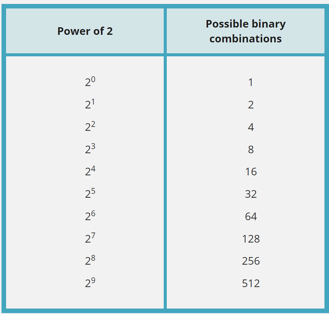
602.4.2 Powers of 2: Why Binary Uses These Numbers
Binary groupings are always powers of 2:
| Bits | Calculation | Possible Values | Range |
|---|---|---|---|
| 1 | 21 | 2 | 0-1 |
| 2 | 22 | 4 | 0-3 |
| 4 | 24 | 16 | 0-15 |
| 8 | 28 | 256 | 0-255 |
| 10 | 210 | 1,024 | 0-1023 |
| 12 | 212 | 4,096 | 0-4095 |
| 16 | 216 | 65,536 | 0-65535 |
| 32 | 232 | 4,294,967,296 | 0-4.3 billion |
Why This Matters for IoT: - 8-bit ADC: 256 different sensor values - 10-bit ADC: 1,024 values (typical Arduino) - 12-bit ADC: 4,096 values (typical ESP32) - 16-bit ADC: 65,536 values (high-precision sensors)
602.5 Binary Number System
602.5.1 Place Value in Binary
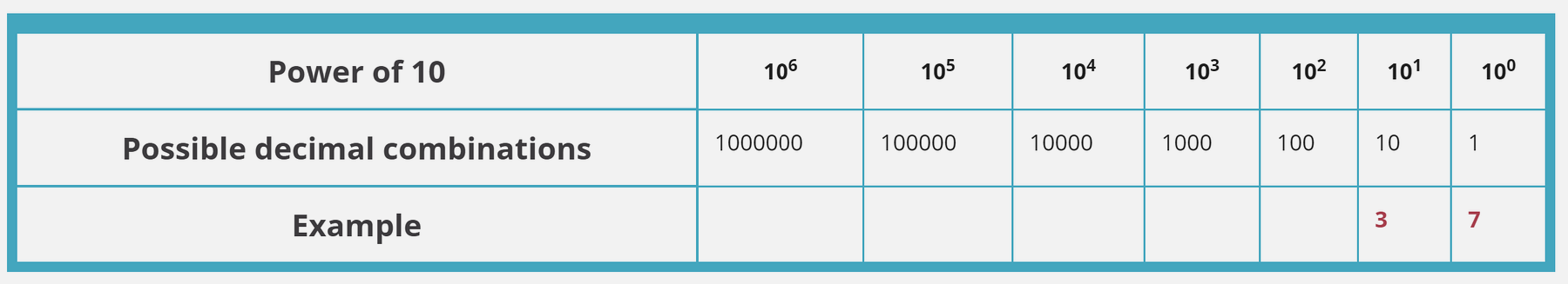
Just like decimal uses powers of 10, binary uses powers of 2:
Decimal (base 10):
237 = (2 × 10²) + (3 × 10¹) + (7 × 10⁰)
= (2 × 100) + (3 × 10) + (7 × 1)
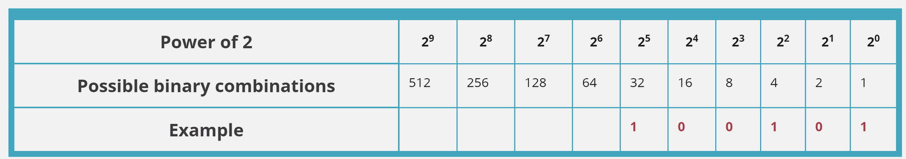
= 200 + 30 + 7Binary (base 2):
101 = (1 × 2²) + (0 × 2¹) + (1 × 2⁰)
    = (1 × 4) + (0 × 2) + (1 × 1)
    = 4 + 0 + 1
    = 5 (in decimal)
602.5.2 Example: Convert Decimal 37 to Binary
Step 1: Find largest power of 2 ≤ 37
| Position | 25 | 24 | 23 | 22 | 21 | 20 |
|---|---|---|---|---|---|---|
| Value | 32 | 16 | 8 | 4 | 2 | 1 |
| Bit | 1 | 0 | 0 | 1 | 0 | 1 |
Step 2: Calculate: - 37 ÷ 32 = 1 remainder 5 → Bit 5 = 1 - 5 ÷ 16 = 0 → Bit 4 = 0 - 5 ÷ 8 = 0 → Bit 3 = 0 - 5 ÷ 4 = 1 remainder 1 → Bit 2 = 1 - 1 ÷ 2 = 0 → Bit 1 = 0 - 1 ÷ 1 = 1 → Bit 0 = 1
Result: 37decimal = 100101binary
Verification: (1×32) + (0×16) + (0×8) + (1×4) + (0×2) + (1×1) = 32 + 4 + 1 = 37 ✓
TipVideo: Introduction to Binary Numbers
Recommended: Intro to Binary Numbers (10 minutes)
Visual explanation of binary counting, conversion, and why computers use base-2.
602.6 Floating Point Numbers
Problem: How to represent very large or very small numbers efficiently?
Solution: Floating point notation (scientific notation for computers)
602.6.1 Decimal Scientific Notation
Instead of: - 300,000,000,000 → Write: 3 × 10¹¹ - 0.000000000015 → Write: 1.5 × 10⁻¹¹
602.6.2 Binary Floating Point (IEEE 754)
32-bit float representation:
| Sign | Exponent | Mantissa |
|---|---|---|
| 1 bit | 8 bits | 23 bits |
Example: 3.14159… stored as: - Sign: 0 (positive) - Exponent: Adjusted power - Mantissa: Fractional part
IoT Relevance: - Arduino: Supports 32-bit floats - ESP32: Hardware floating-point unit (FPU) - Sensors: Temperature as 23.456°C stored efficiently
WarningFloating Point Precision Limitations
Never compare floats with == in code!
Due to rounding errors, 0.1 + 0.2 may not exactly equal 0.3.
Correct:
if (abs(value1 - value2) < 0.0001) {
    // Close enough!
}
TipVideo: Floating Point Numbers
Recommended: Floating Point Numbers Explained (12 minutes)
How computers represent decimal numbers and why precision matters.
602.7 Quiz: Binary Fundamentals
NoteQuestion 1: Binary Conversion
What is the decimal value of binary 1101?
A) 11 B) 13 C) 15 D) 9
Show Answer
Answer: B) 13
\[1101_2 = (1×8) + (1×4) + (0×2) + (1×1) = 8 + 4 + 0 + 1 = 13_{10}\]
NoteQuestion 2: Powers of 2
How many different values can a 16-bit ADC represent?
A) 16,384 B) 32,768 C) 65,536 D) 131,072
Show Answer
Answer: C) 65,536
\[Values = 2^{bits} = 2^{16} = 65,536\]
The actual digital output ranges from 0 to 65,535 (one less than total values).
NoteQuestion 3: Floating Point Comparison
Why should you avoid using == to compare floating-point numbers?
A) It’s too slow B) Rounding errors make exact comparison unreliable C) Floating-point numbers can’t be compared D) It causes compiler errors
Show Answer
Answer: B) Rounding errors make exact comparison unreliable
Due to binary representation limitations, 0.1 + 0.2 may not exactly equal 0.3.
Correct approach: Use threshold comparison like abs(a - b) < 0.0001.
602.8 Summary
This chapter covered the binary number system - the foundation for all digital electronics:
- Analog vs. Digital: Real-world signals are continuous (analog); computers work with discrete values (digital)
- Binary (Base-2): Uses only 0 and 1; each position represents a power of 2
- Powers of 2: Determine ADC/DAC resolution (8-bit = 256 values, 12-bit = 4,096 values)
- Place Value: Convert binary to decimal by summing bit × 2position
- Floating Point: IEEE 754 representation allows efficient storage of very large/small numbers
- Precision Pitfalls: Never use
==for float comparison; use threshold-based comparison
Understanding binary is essential for interpreting ADC values, calculating memory requirements, and debugging sensor data in IoT systems.
602.9 What’s Next?
Now that you understand binary representation, continue to learn about how Analog-to-Digital Converters (ADCs) use these concepts to convert sensor voltages into digital values.
Continue to ADC Fundamentals →
NoteRelated Chapters & Resources
In This Series: - ADC Fundamentals - How ADCs convert analog to digital - Nyquist Sampling Theory - Sampling rate requirements - ADC/DAC Worked Examples - Practical calculations - DAC and PWM Output - Digital-to-analog conversion
Foundation: - Electricity - Electrical fundamentals - Electronics - Components overview