%%{init: {'theme': 'base', 'themeVariables': {'primaryColor':'#E8F4F8','primaryTextColor':'#2C3E50','primaryBorderColor':'#16A085','lineColor':'#16A085','secondaryColor':'#FEF5E7','tertiaryColor':'#FDEBD0','fontSize':'14px'}}}%%
graph TB
    Packet["Incoming Packet"]

    subgraph Switch["OpenFlow Switch"]
        FlowTable["Flow Table<br/>Match-Action Rules"]
        GroupTable["Group Table<br/>Multicast/Failover"]
        Meter["Meter Table<br/>Rate Limiting"]
        SecureChannel["Secure Channel<br/>(TLS to Controller)"]
    end

    Controller["SDN Controller"]
    Output["Output Port(s)"]

    Packet -->|1. Arrives| FlowTable
    FlowTable -->|2. Match?| Decision{Match<br/>Found?}
    Decision -->|Yes| Action["Execute Actions"]
    Decision -->|No| SecureChannel

    SecureChannel -->|PACKET_IN| Controller
    Controller -->|FLOW_MOD| SecureChannel
    SecureChannel --> FlowTable

    Action --> GroupTable
    Action --> Meter
    GroupTable --> Output
    Meter --> Output

    style FlowTable fill:#16A085,stroke:#2C3E50,color:#fff
    style GroupTable fill:#2C3E50,stroke:#16A085,color:#fff
    style Meter fill:#2C3E50,stroke:#16A085,color:#fff
    style SecureChannel fill:#E67E22,stroke:#2C3E50,color:#fff
    style Controller fill:#16A085,stroke:#2C3E50,color:#fff,stroke-width:3px
    style Decision fill:#FDEBD0,stroke:#E67E22
    style Action fill:#E8F4F8,stroke:#16A085
283 SDN OpenFlow Protocol
283.1 Learning Objectives
By the end of this chapter, you will be able to:
- Configure OpenFlow: Set up basic OpenFlow rules for packet forwarding and network management
- Understand Flow Tables: Describe flow table entry structure including match fields, actions, and timeouts
- Analyze Flow Processing: Trace packet processing through OpenFlow switch pipeline
- Address SDN Challenges: Identify TCAM limitations and controller placement strategies
TipFor Kids: Meet the Sensor Squad!
OpenFlow is like a recipe book that tells kitchen workers exactly what to do with each ingredient!
283.1.1 The Sensor Squad Adventure: The Recipe Book
Remember Connie the Controller from the traffic jam story? Well, Connie needed a way to give instructions to ALL the network switches. It was like being a head chef in a giant kitchen - how do you tell hundreds of cooks what to do?
“I’ll use a recipe book!” Connie announced. “It’s called OpenFlow!”
Here’s how it works: Connie writes recipes (called “flow rules”) and sends them to each switch. The recipe says things like:
- “If you see a message from Thermo (temperature sensor), send it to Port 5”
- “If you see an emergency message, forward it immediately - highest priority!”
- “If you don’t know what to do, ask me!”
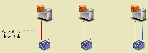
Power Pete was curious: “What happens when a new message arrives that doesn’t match any recipe?”
“Great question!” said Connie. “The switch says ‘PACKET_IN!’ which means ‘Chef, I got a new ingredient I don’t recognize!’ Then I write a new recipe and send a ‘FLOW_MOD’ message which means ‘Here’s how to handle that from now on!’”
Now ALL the switches in the network use the same recipe book, and they all know exactly what to do!
283.1.2 Key Words for Kids
| Word | What It Means |
|---|---|
| Flow Rule | A recipe that tells a switch what to do when it sees a specific type of message |
| PACKET_IN | When a switch says “Help! I don’t know what to do with this!” |
| FLOW_MOD | When the controller says “Here’s a new recipe for you!” |
| Flow Table | The recipe book stored in each switch |
283.2 Introduction
OpenFlow is the standardized southbound protocol for communication between SDN controllers and switches. It defines how controllers program switch forwarding behavior through flow rules.

283.3 OpenFlow Switch Components
{fig-alt=“OpenFlow switch components showing packet processing pipeline: incoming packets match against flow table, execute actions via group/meter tables to output ports, or send PACKET_IN to controller via secure channel for new flow rules”}
283.3.1 Switch Components
An OpenFlow switch contains several key components:
1. Flow Tables - Store match-action rules - Multiple tables form a pipeline - Each table processed sequentially
2. Group Tables - Enable multicast (one packet to multiple ports) - Fast failover (backup paths) - Load balancing (select action)
3. Meter Tables - Rate limiting per flow - QoS enforcement - Bandwidth management
4. Secure Channel - TLS-encrypted connection to controller - Handles OpenFlow messages
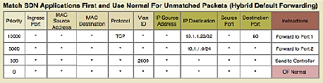
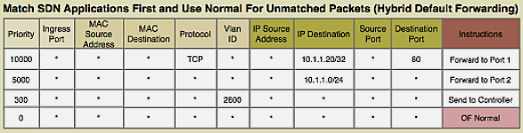
283.4 Flow Table Entry Structure
Each flow entry contains the following fields:
1. Match Fields (Packet Header Fields): - Layer 2: Source/Dest MAC, VLAN ID, Ethertype - Layer 3: Source/Dest IP, Protocol, ToS - Layer 4: Source/Dest Port (TCP/UDP) - Input Port - Metadata
2. Priority: - Higher priority rules matched first - Allows specific rules to override general rules
3. Counters: - Packets matched - Bytes matched - Duration
4. Instructions/Actions: - Forward to port(s) - Drop - Modify header fields (MAC, IP, VLAN) - Push/Pop VLAN/MPLS tags - Send to controller - Go to next table
5. Timeouts: - Idle Timeout: Remove rule if no matching packets for N seconds - Hard Timeout: Remove rule after N seconds regardless of activity
6. Cookie: - Opaque identifier set by controller
Example Flow Rule:
Match: src_ip=10.0.0.5, dst_ip=192.168.1.10, protocol=TCP, dst_port=80
Priority: 100
Actions: output:port3, set_vlan=100
Idle_timeout: 60
Hard_timeout: 300
283.5 OpenFlow Messages
OpenFlow defines several message types for controller-switch communication:
283.5.1 Controller-to-Switch Messages
| Message | Purpose |
|---|---|
| FLOW_MOD | Add, modify, or delete flow rules |
| PACKET_OUT | Send packet out specific port |
| BARRIER | Request confirmation that prior messages processed |
| GET_CONFIG | Query switch configuration |
| SET_CONFIG | Modify switch configuration |
| MULTIPART_REQUEST | Request statistics |
283.5.2 Switch-to-Controller Messages
| Message | Purpose |
|---|---|
| PACKET_IN | Send packet to controller (no matching rule) |
| FLOW_REMOVED | Notify controller of expired/deleted flow |
| PORT_STATUS | Notify controller of port state changes |
| ERROR | Report errors |
283.5.3 Symmetric Messages
| Message | Purpose |
|---|---|
| HELLO | Connection establishment |
| ECHO_REQUEST/REPLY | Keepalive, latency measurement |
| EXPERIMENTER | Vendor extensions |
283.6 SDN Challenges
283.6.1 Rule Placement Challenge
Problem: Switches have limited TCAM (Ternary Content-Addressable Memory) for storing flow rules.
TCAM Characteristics: - Fast lookup (single clock cycle) - Expensive ($15-30 per Mb) - Limited capacity (few thousand entries) - Power-hungry
Challenges: - How to select which flows to cache in TCAM? - When to evict rules (LRU, LFU, timeout-based)? - How to minimize PACKET_IN messages to controller?
Solutions: - Wildcard Rules: Match multiple flows with single rule - Hierarchical Aggregation: Aggregate at network edge - Rule Caching: Intelligent replacement algorithms - Hybrid Approaches: TCAM + DRAM for overflow
283.6.2 Controller Placement Challenge

Problem: Where to place controllers for optimal performance?
Considerations: - Latency: Controller-switch delay affects flow setup time - Throughput: Controller capacity (requests/second) - Reliability: Controller failure impacts network - Scalability: Number of switches per controller
Architectures:
%%{init: {'theme': 'base', 'themeVariables': {'primaryColor':'#E8F4F8','primaryTextColor':'#2C3E50','primaryBorderColor':'#16A085','lineColor':'#16A085','secondaryColor':'#FEF5E7','tertiaryColor':'#FDEBD0','fontSize':'14px'}}}%%
graph TB
    subgraph Centralized["Centralized (Single Controller)"]
        C1["Controller"]
        S1["Switch"] & S2["Switch"] & S3["Switch"]
        C1 --> S1 & S2 & S3
    end

    subgraph Distributed["Distributed (Multiple Controllers)"]
        C2A["Controller A"] & C2B["Controller B"]
        S4["Switch"] & S5["Switch"] & S6["Switch"]
        C2A <-->|Sync| C2B
        C2A --> S4 & S5
        C2B --> S5 & S6
    end

    subgraph Hierarchical["Hierarchical (Tiered Controllers)"]
        C3Root["Root Controller"]
        C3A["Regional A"] & C3B["Regional B"]
        S7["Switch"] & S8["Switch"] & S9["Switch"] & S10["Switch"]
        C3Root --> C3A & C3B
        C3A --> S7 & S8
        C3B --> S9 & S10
    end

    style C1 fill:#16A085,stroke:#2C3E50,color:#fff
    style C2A fill:#16A085,stroke:#2C3E50,color:#fff
    style C2B fill:#16A085,stroke:#2C3E50,color:#fff
    style C3Root fill:#E67E22,stroke:#2C3E50,color:#fff
    style C3A fill:#16A085,stroke:#2C3E50,color:#fff
    style C3B fill:#16A085,stroke:#2C3E50,color:#fff
    style S1 fill:#2C3E50,stroke:#16A085,color:#fff
    style S2 fill:#2C3E50,stroke:#16A085,color:#fff
    style S3 fill:#2C3E50,stroke:#16A085,color:#fff
    style S4 fill:#2C3E50,stroke:#16A085,color:#fff
    style S5 fill:#2C3E50,stroke:#16A085,color:#fff
    style S6 fill:#2C3E50,stroke:#16A085,color:#fff
    style S7 fill:#2C3E50,stroke:#16A085,color:#fff
    style S8 fill:#2C3E50,stroke:#16A085,color:#fff
    style S9 fill:#2C3E50,stroke:#16A085,color:#fff
    style S10 fill:#2C3E50,stroke:#16A085,color:#fff
{fig-alt=“Three SDN controller placement architectures: centralized (single controller managing all switches), distributed (multiple synchronized controllers for redundancy), and hierarchical (root controller coordinating regional controllers managing switch groups)”}
Placement Strategies: - K-median: Minimize average latency to switches - K-center: Minimize maximum latency (worst-case) - Failure-aware: Ensure backup controller coverage
NoteAlternative View: Controller Failure Recovery Sequence
This variant shows what happens during a controller failure in a distributed deployment, demonstrating the failover process that maintains network operation.
%%{init: {'theme': 'base', 'themeVariables': {'primaryColor':'#2C3E50','primaryTextColor':'#fff','primaryBorderColor':'#16A085','lineColor':'#16A085','secondaryColor':'#E67E22','tertiaryColor':'#7F8C8D','fontSize':'12px'}}}%%
sequenceDiagram
    participant S as Switch
    participant P as Primary Controller
    participant B as Backup Controller
    participant DB as State Database

    Note over S,DB: Normal Operation
    S->>P: PACKET_IN (new flow)
    P->>DB: Store flow decision
    P->>S: FLOW_MOD (install rule)

    Note over P: Controller Fails
    P--xP: Crash / Network Partition

    Note over S,B: Failover Process (~3-5 seconds)
    S->>P: Heartbeat
    S->>S: No response (timeout 3s)
    S->>B: Connect to backup

    B->>DB: Load latest state
    DB-->>B: Network topology + flows
    B->>B: Become primary (leader election)

    B->>S: HELLO (establish connection)
    S->>B: FEATURES_REQUEST
    B-->>S: FEATURES_REPLY

    Note over S,B: Normal Operation Resumed
    S->>B: PACKET_IN (new flow)
    B->>S: FLOW_MOD (install rule)

    Note over S,DB: Existing flows continued<br/>during entire failover
NoteAlternative View: Controller Placement Trade-off Matrix
This variant presents controller architecture selection as a decision matrix, helping students choose the right approach for their IoT deployment scale.
%%{init: {'theme': 'base', 'themeVariables': {'primaryColor':'#2C3E50','primaryTextColor':'#fff','primaryBorderColor':'#16A085','lineColor':'#16A085','secondaryColor':'#E67E22','tertiaryColor':'#7F8C8D','fontSize':'14px'}}}%%
flowchart TB
    Start([Network Scale?]) --> Q1{Switches<br/>< 100?}

    Q1 -->|Yes| Centralized["CENTRALIZED<br/>───────────<br/>Simple management<br/>Low cost<br/>Easy debugging<br/>───────────<br/>Single point of failure<br/>Limited scalability<br/>───────────<br/>Small campus<br/>Lab/prototype"]

    Q1 -->|No| Q2{Switches<br/>< 1000?}

    Q2 -->|Yes| Distributed["DISTRIBUTED<br/>───────────<br/>High availability<br/>Geographic spread<br/>Load balancing<br/>───────────<br/>Sync complexity<br/>Consistency delays<br/>───────────<br/>Enterprise<br/>Multi-site IoT"]

    Q2 -->|No| Hierarchical["HIERARCHICAL<br/>───────────<br/>Massive scale<br/>Domain isolation<br/>Regional autonomy<br/>───────────<br/>Complex operations<br/>Multiple failure domains<br/>───────────<br/>Smart city<br/>Carrier network"]

    style Centralized fill:#16A085,stroke:#2C3E50,color:#fff
    style Distributed fill:#E67E22,stroke:#2C3E50,color:#fff
    style Hierarchical fill:#2C3E50,stroke:#16A085,color:#fff
283.7 Knowledge Check
283.8 Visual Reference Gallery
NoteVisual: OpenFlow Protocol

283.9 Summary
This chapter covered the OpenFlow protocol and SDN challenges:
Key Takeaways:
OpenFlow Switch Components: Flow tables for match-action rules, group tables for multicast/failover, meter tables for rate limiting, and secure channel for controller communication
Flow Table Entry Structure: Match fields (L2-L4 headers), priority, counters, instructions/actions, timeouts (idle and hard), and cookie
OpenFlow Messages: Controller-to-switch (FLOW_MOD, PACKET_OUT), switch-to-controller (PACKET_IN, FLOW_REMOVED), and symmetric (HELLO, ECHO)
Rule Placement Challenge: TCAM limitations require wildcard rules, hierarchical aggregation, and intelligent caching strategies
Controller Placement: Centralized (simple, single point of failure), distributed (high availability, sync complexity), and hierarchical (massive scale, regional autonomy)
Understanding OpenFlow mechanics is essential for implementing and troubleshooting SDN deployments in IoT environments.
283.10 What’s Next?
Explore how SDN is applied specifically to IoT networks, wireless sensor networks, and mobile environments.