%%{init: {'theme': 'base', 'themeVariables': {'primaryColor': '#2C3E50', 'primaryTextColor': '#fff', 'primaryBorderColor': '#16A085', 'lineColor': '#E67E22', 'secondaryColor': '#16A085', 'tertiaryColor': '#E67E22', 'clusterBkg': '#f9f9f9', 'clusterBorder': '#2C3E50', 'fontSize': '13px'}}}%%
graph TB
    subgraph Application["Application Layer"]
        APP1[Traffic Engineering]
        APP2[Security Apps]
        APP3[Load Balancer]
        APP4[Firewall]
    end

    subgraph Control["Control Layer"]
        CTRL[SDN Controller<br/>Network OS]
        TOPO[Topology Manager]
        ROUTING[Routing Engine]
        STATS[Statistics Collector]
    end

    subgraph Infrastructure["Infrastructure Layer"]
        SW1[OpenFlow Switch 1]
        SW2[OpenFlow Switch 2]
        SW3[OpenFlow Switch 3]
        SW4[OpenFlow Switch 4]
    end

    APP1 -->|Northbound API| CTRL
    APP2 -->|Northbound API| CTRL
    APP3 -->|Northbound API| CTRL
    APP4 -->|Northbound API| CTRL

    CTRL --> TOPO
    CTRL --> ROUTING
    CTRL --> STATS

    CTRL -->|Southbound API<br/>OpenFlow| SW1
    CTRL -->|Southbound API<br/>OpenFlow| SW2
    CTRL -->|Southbound API<br/>OpenFlow| SW3
    CTRL -->|Southbound API<br/>OpenFlow| SW4

    style APP1 fill:#E67E22,stroke:#2C3E50,color:#fff
    style APP2 fill:#E67E22,stroke:#2C3E50,color:#fff
    style CTRL fill:#2C3E50,stroke:#16A085,color:#fff
    style SW1 fill:#16A085,stroke:#2C3E50,color:#fff
    style SW2 fill:#16A085,stroke:#2C3E50,color:#fff
    style SW3 fill:#16A085,stroke:#2C3E50,color:#fff
    style SW4 fill:#16A085,stroke:#2C3E50,color:#fff
285 SDN Three-Layer Architecture
285.1 Learning Objectives
By the end of this chapter, you will be able to:
- Describe the Three-Layer SDN Architecture: Explain the application, control, and infrastructure layers and their interactions
- Understand SDN Controller Design: Identify controller components including topology manager, routing engine, and statistics collector
- Evaluate Controller Architectures: Compare centralized, distributed, and hierarchical controller deployments
- Apply SDN Layers to IoT: Map IoT network requirements to SDN architectural components
TipMVU: Minimum Viable Understanding
Core concept: SDN uses a three-layer architecture: Application layer (network apps using APIs), Control layer (SDN controller with global view), and Infrastructure layer (OpenFlow switches forwarding packets). Why it matters: This separation enables network programmability - applications request network behavior through APIs rather than configuring individual devices. Key takeaway: The controller is the “brain” of SDN, but it doesn’t forward packets - it programs switches with flow rules that enable wire-speed forwarding in hardware.
285.2 Prerequisites
- SDN Core Concepts: Understanding of control/data plane separation and traditional network limitations
285.3 SDN Architecture Overview
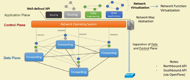


SDN introduces three-layer architecture with clean separation of concerns:
%%{init: {'theme': 'base', 'themeVariables': {'primaryColor': '#2C3E50', 'primaryTextColor': '#fff', 'primaryBorderColor': '#16A085', 'lineColor': '#E67E22', 'secondaryColor': '#16A085', 'tertiaryColor': '#E67E22', 'clusterBkg': '#f9f9f9', 'clusterBorder': '#2C3E50', 'fontSize': '13px'}}}%%
graph TB
    subgraph Cloud["Cloud / Data Center"]
        APP[Network Applications<br/>Traffic Engineering, Security]
        CTRL1[Primary Controller<br/>OpenDaylight/ONOS]
        CTRL2[Backup Controller<br/>High Availability]
        DB[(Network State DB<br/>Topology, Flows)]
    end

    subgraph Edge["Edge / Campus"]
        GW[SDN Gateway<br/>Protocol Translation]
        SW1[Core Switch<br/>OpenFlow 1.3]
        SW2[Core Switch<br/>OpenFlow 1.3]
    end

    subgraph Access["Access Layer"]
        ASW1[Access Switch 1]
        ASW2[Access Switch 2]
        ASW3[Access Switch 3]
    end

    subgraph IoTDevices["IoT Devices"]
        IOT1[Sensors]
        IOT2[Actuators]
        IOT3[Gateways]
    end

    APP --> CTRL1
    CTRL1 <--> CTRL2
    CTRL1 --> DB
    CTRL2 --> DB

    CTRL1 -->|OpenFlow over TLS| GW
    GW --> SW1
    GW --> SW2

    SW1 --> ASW1
    SW1 --> ASW2
    SW2 --> ASW2
    SW2 --> ASW3

    ASW1 --> IOT1
    ASW2 --> IOT2
    ASW3 --> IOT3

    style Cloud fill:#2C3E50,color:#fff
    style Edge fill:#16A085,color:#fff
    style Access fill:#E67E22,color:#fff
    style IoTDevices fill:#7F8C8D,color:#fff
%%{init: {'theme': 'base', 'themeVariables': {'primaryColor': '#2C3E50', 'primaryTextColor': '#fff', 'primaryBorderColor': '#16A085', 'lineColor': '#E67E22', 'secondaryColor': '#16A085', 'fontSize': '12px'}}}%%
sequenceDiagram
    participant IOT as IoT Device
    participant SW as OpenFlow Switch
    participant CTRL as SDN Controller
    participant APP as Network App

    Note over IOT,APP: New Flow - First Packet

    IOT->>SW: Packet arrives (no matching rule)
    SW->>CTRL: PACKET_IN (unknown flow)

    CTRL->>APP: Query: How to handle?
    APP->>CTRL: Policy: Allow, QoS High

    CTRL->>CTRL: Compute optimal path
    CTRL->>SW: FLOW_MOD (install rule)

    SW->>SW: Add to flow table:<br/>Match: src=IOT, dst=Cloud<br/>Action: output port 3

    SW->>IOT: Forward packet (via port 3)

    Note over IOT,APP: Subsequent Packets - Same Flow

    IOT->>SW: More packets (same flow)
    SW->>SW: Match found in flow table
    SW->>IOT: Forward at line rate<br/>Controller not involved

    Note over IOT,APP: Controller only handles first packet
{fig-alt=“SDN three-layer architecture diagram: application layer with traffic engineering, security apps, load balancer, and firewall connecting via northbound API to control layer (SDN controller with topology manager, routing engine, statistics collector) which connects via southbound OpenFlow API to infrastructure layer with four OpenFlow switches”}
285.4 Application Layer
Purpose: Network applications that define desired network behavior.
Applications: - Traffic Engineering: Optimize paths based on network conditions - Security: Firewall, IDS/IPS, DDoS mitigation - Load Balancing: Distribute traffic across servers - Network Monitoring: Real-time traffic analysis - QoS Management: Prioritize critical IoT traffic
Interface: Northbound APIs (REST, JSON-RPC, gRPC)
285.5 Control Layer (SDN Controller)
Purpose: Brain of the network—maintains global view and makes routing decisions.
WarningTradeoff: Centralized vs Distributed SDN Controller
Option A: Centralized Controller - Single controller instance manages entire network with complete global view. Simpler architecture but creates single point of failure.
Option B: Distributed Controller Cluster - Multiple controller instances share state and load. Higher availability but increased complexity and synchronization overhead.
Decision Factors:
Choose Centralized when: Network has fewer than 500 switches, latency requirements are relaxed (>10ms acceptable), budget constraints limit infrastructure, or simplicity is prioritized over availability. Typical failover time: 30-60 seconds with warm standby.
Choose Distributed when: Network exceeds 1,000 switches, five-nines availability (99.999%) is required, geographic distribution spans multiple sites, or control plane latency must stay under 5ms. Typical failover time: 2-5 seconds with active-active clustering.
Cost comparison: Centralized (2 VMs for primary/backup) costs ~$200/month. Distributed 3-node cluster (ONOS, OpenDaylight) costs ~$600/month but handles 10x more switches and provides sub-second failover. At 10,000+ devices, distributed becomes mandatory regardless of cost.

Responsibilities: - Compute forwarding paths - Install flow rules in switches - Handle switch events (new flows, link failures) - Provide network state to applications - Maintain network topology

Popular Controllers: - OpenDaylight: Java-based, modular, widely adopted - ONOS: High availability, scalability for carriers - Ryu: Python-based, easy development - POX/NOX: Educational, Python/C++ - Floodlight: Java, fast performance
285.6 Data/Infrastructure Layer
Purpose: Packet forwarding based on flow rules installed by controller.

Components: - OpenFlow Switches: Hardware or software switches - Flow Tables: Store forwarding rules (match-action) - Secure Channel: Connection to controller (TLS)

Flow Processing: 1. Packet arrives at switch 2. Match against flow table 3. If match: execute action (forward, drop, modify) 4. If no match: send to controller (PACKET_IN)
WarningTradeoff: Proactive vs Reactive Flow Installation
Option A: Proactive Flow Installation - Controller pre-installs flow rules for all expected traffic patterns before packets arrive. First packet forwarded immediately at line rate.
Option B: Reactive Flow Installation - Controller installs flow rules only when first packet of new flow triggers PACKET_IN. Flexible but adds latency for first packet.
Decision Factors:
Choose Proactive when: Traffic patterns are predictable (IoT sensors with known destinations), first-packet latency is critical (<1ms required), controller resources are limited, or network operates in environments where controller connectivity may be intermittent.
Choose Reactive when: Traffic patterns are dynamic and unpredictable, flow table memory is constrained (reactive uses space only for active flows), fine-grained per-flow policies are needed, or network topology changes frequently requiring adaptive routing.
Latency comparison: Proactive achieves ~50 microseconds (hardware forwarding only). Reactive adds 5-50ms for first packet (controller round-trip) but subsequent packets match installed rule at line rate. For IoT sensor networks with 1000+ devices sending periodic telemetry, proactive saves 5-50ms × 1000 = 5-50 seconds of cumulative delay per reporting interval.
285.7 Knowledge Check
Test your understanding of SDN architecture concepts.
285.8 Summary
This chapter explored the SDN three-layer architecture:
- Application Layer: Network applications (traffic engineering, security, load balancing) using northbound APIs (REST, gRPC) to request network behavior
- Control Layer: SDN controller as the network “brain” with topology manager, routing engine, and statistics collector - providing global network view and installing flow rules
- Infrastructure Layer: OpenFlow switches executing flow rules in hardware at wire-speed, with flow tables storing match-action rules
- Controller Tradeoffs: Centralized (simple, single point of failure) vs distributed (scalable, complex synchronization) architectures
- Flow Installation: Proactive (pre-installed, low latency) vs reactive (on-demand, flexible) strategies
285.9 What’s Next
The next chapter examines OpenFlow Protocol in detail, exploring flow table structure, message types, and the mechanics of controller-switch communication.