%%{init: {'theme': 'base', 'themeVariables': {'primaryColor':'#E8F4F8','primaryTextColor':'#2C3E50','primaryBorderColor':'#16A085','lineColor':'#16A085','secondaryColor':'#FEF5E7','tertiaryColor':'#FDEBD0','fontSize':'14px'}}}%%
graph TB
    L1["Traffic Light 1<br/>(Makes own decision)"]
    L2["Traffic Light 2<br/>(Makes own decision)"]
    L3["Traffic Light 3<br/>(Makes own decision)"]
    L4["Traffic Light 4<br/>(Makes own decision)"]

    L1 -.No coordination.-> L2
    L2 -.No coordination.-> L3
    L3 -.No coordination.-> L4
    L4 -.No coordination.-> L1

    style L1 fill:#E67E22,stroke:#2C3E50,color:#fff
    style L2 fill:#E67E22,stroke:#2C3E50,color:#fff
    style L3 fill:#E67E22,stroke:#2C3E50,color:#fff
    style L4 fill:#E67E22,stroke:#2C3E50,color:#fff
278 SDN Architecture Fundamentals
278.1 Learning Objectives
By the end of this chapter, you will be able to:
- Explain SDN Architecture: Describe the separation of control and data planes in software-defined networks
- Understand the Three-Layer Model: Differentiate application, control, and data layers and their interfaces
- Compare Traditional vs SDN: Analyze limitations of traditional networks and how SDN addresses them
- Apply SDN Concepts: Recognize use cases where SDN provides significant advantages
TipFor Kids: Meet the Sensor Squad!
Software-Defined Networking is like having one super-smart traffic controller instead of every intersection making its own decisions!
278.1.1 The Sensor Squad Adventure: The Traffic Jam Solution
The Sensor Squad had grown SO big! There were hundreds of sensors all over the smart city - Sunny the Light Sensors on every street lamp, Thermo the Temperature Sensors in every building, Motion Mo the Motion Detectors watching every crosswalk. But there was a problem: messages were getting lost and stuck!
“My temperature warning took forever to get through!” complained Thermo. “The network was jammed!”
Motion Mo nodded. “Every switch and router was making its own decisions about where to send messages. It was like having every traffic light in the city decide on its own when to turn green - total chaos!”
That’s when Signal Sam the Communication Expert introduced a brilliant new friend: Connie the Controller. Connie could see the ENTIRE network from above, like a bird watching all the city streets at once. Instead of every switch deciding on its own, Connie made ALL the routing decisions from one central place.
“Temperature emergency on Oak Street?” Connie announced. “I’ll create a fast lane RIGHT NOW!” With one command, Connie told all the switches to prioritize Thermo’s message. Power Pete the Battery Manager was impressed: “Connie can even turn off unused network paths to save energy!”
The Sensor Squad cheered. Now ALL their messages flowed smoothly because one smart controller was orchestrating everything!
278.1.2 Key Words for Kids
| Word | What It Means |
|---|---|
| Software-Defined Networking | Having one smart “brain” that controls how all messages travel through the network, instead of each part deciding alone |
| Controller | The central brain that sees everything and tells all the network switches where to send messages |
| OpenFlow | The special language the controller uses to give instructions to all the network switches |
278.1.3 Try This at Home!
Play the “Traffic Controller” game:
Setup: Draw a simple grid of 4-6 “intersections” (dots) on paper. Place toy cars or game pieces as “messages” that need to travel from one side to another.
Round 1 - No Controller: Each “intersection” flips a coin to decide which way messages go. Watch how chaotic and slow it gets!
Round 2 - With Controller: One person is the “SDN Controller” who can see the whole grid. They decide the best path for EVERY message. Much faster and organized!
Discuss: Why is having one smart controller better than everyone deciding on their own? When might you need a REALLY fast controller?
278.2 Prerequisites
Before diving into this chapter, you should be familiar with:
- Networking Basics: Understanding fundamental networking concepts including IP addressing, routing, switching, and network protocols is essential for grasping how SDN separates the control and data planes
- SDN Fundamentals and OpenFlow: Core SDN concepts, OpenFlow protocol basics, and the architectural principles of programmable networks provide the foundation for advanced SDN implementations in IoT
- WSN Overview: Fundamentals: Knowledge of wireless sensor network architectures helps understand how SDN can optimize IoT device management and multi-hop routing decisions
NoteKey Concepts
- Software-Defined Networking (SDN): Network architecture decoupling control plane (decision-making) from data plane (packet forwarding) for centralized programmable control
- Control Plane: Centralized intelligence determining how network traffic should be routed and managed across the network
- Data Plane: Distributed forwarding infrastructure executing packet transmission decisions made by the control plane
- OpenFlow: Protocol enabling SDN controllers to communicate with network switches, instructing them how to forward packets
- Network Programmability: Ability to dynamically modify network behavior through software without reconfiguring hardware devices
- SDN Controller: Centralized software application managing network-wide policies and configuring individual network devices
278.3 Getting Started (For Beginners)
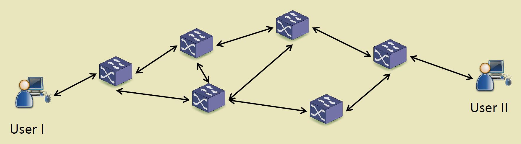
278.3.1 The Problem with Traditional Networks
Analogy: A City Without Central Traffic Control
Imagine a city where every traffic light makes its own decisions:
{fig-alt=“Traditional network analogy showing four traffic lights each making independent decisions with no central coordination, illustrating distributed control where each device operates autonomously”}
This is how traditional networks work: - Each router/switch makes its own forwarding decisions - No centralized view of the whole network - Changes require configuring each device individually - No easy way to respond to network-wide events
278.3.2 SDN: Centralized Control
Analogy: Smart City Traffic Control Center
%%{init: {'theme': 'base', 'themeVariables': {'primaryColor':'#E8F4F8','primaryTextColor':'#2C3E50','primaryBorderColor':'#16A085','lineColor':'#16A085','secondaryColor':'#FEF5E7','tertiaryColor':'#FDEBD0','fontSize':'14px'}}}%%
graph TB
    Controller["Traffic Control Center<br/>(Makes all decisions)"]
    L1["Light 1<br/>(Executes)"]
    L2["Light 2<br/>(Executes)"]
    L3["Light 3<br/>(Executes)"]
    L4["Light 4<br/>(Executes)"]

    Controller -->|Commands| L1
    Controller -->|Commands| L2
    Controller -->|Commands| L3
    Controller -->|Commands| L4

    L1 -->|Status| Controller
    L2 -->|Status| Controller
    L3 -->|Status| Controller
    L4 -->|Status| Controller

    style Controller fill:#16A085,stroke:#2C3E50,color:#fff,stroke-width:3px
    style L1 fill:#2C3E50,stroke:#16A085,color:#fff
    style L2 fill:#2C3E50,stroke:#16A085,color:#fff
    style L3 fill:#2C3E50,stroke:#16A085,color:#fff
    style L4 fill:#2C3E50,stroke:#16A085,color:#fff
{fig-alt=“SDN analogy showing central traffic control center making all decisions and sending commands to traffic lights that simply execute instructions, illustrating centralized control plane”}
278.3.3 The Two “Planes” in SDN
SDN separates the “brain” from the “muscles”:
| Plane | Function | Traditional Network | SDN |
|---|---|---|---|
| Control Plane | Makes decisions (where should this packet go?) | Each device decides | Centralized controller |
| Data Plane | Moves packets (forward, drop, modify) | Same device executes | Simple switches execute |
Analogy: Restaurant Kitchen
%%{init: {'theme': 'base', 'themeVariables': {'primaryColor':'#E8F4F8','primaryTextColor':'#2C3E50','primaryBorderColor':'#16A085','lineColor':'#16A085','secondaryColor':'#FEF5E7','tertiaryColor':'#FDEBD0','fontSize':'14px'}}}%%
graph LR
    subgraph Control["Control Plane (Head Chef)"]
        Chef["Decides: What dish?<br/>Which station?<br/>What priority?"]
    end

    subgraph Data["Data Plane (Line Cooks)"]
        Cook1["Grill Cook<br/>(Executes)"]
        Cook2["Sauté Cook<br/>(Executes)"]
        Cook3["Prep Cook<br/>(Executes)"]
    end

    Chef -->|Orders| Cook1
    Chef -->|Orders| Cook2
    Chef -->|Orders| Cook3

    style Chef fill:#16A085,stroke:#2C3E50,color:#fff
    style Cook1 fill:#2C3E50,stroke:#16A085,color:#fff
    style Cook2 fill:#2C3E50,stroke:#16A085,color:#fff
    style Cook3 fill:#2C3E50,stroke:#16A085,color:#fff
{fig-alt=“Restaurant kitchen analogy showing head chef (control plane) making decisions about dishes and priorities while line cooks (data plane) execute the actual cooking tasks”}
278.3.4 Why SDN for IoT?
IoT networks have unique challenges that SDN solves:
| IoT Challenge | SDN Solution |
|---|---|
| Thousands of devices | Centralized management from one controller |
| Dynamic topology | Instantly reconfigure routes when devices move/fail |
| Diverse requirements | Program different rules for different device types |
| Security threats | Detect attacks from central view, isolate compromised devices |
| Energy efficiency | Route traffic to let unused switches sleep |
Example: Smart Factory
%%{init: {'theme': 'base', 'themeVariables': {'primaryColor':'#E8F4F8','primaryTextColor':'#2C3E50','primaryBorderColor':'#16A085','lineColor':'#16A085','secondaryColor':'#FEF5E7','tertiaryColor':'#FDEBD0','fontSize':'14px'}}}%%
graph TB
    SDN["SDN Controller<br/>(Factory Brain)"]

    subgraph Devices["IoT Devices"]
        Temp["Temperature<br/>Sensors"]
        Robots["Assembly<br/>Robots"]
        Cameras["Vision<br/>Cameras"]
        AGV["Autonomous<br/>Vehicles"]
    end

    SDN -->|"Priority: High QoS"| Robots
    SDN -->|"Route via Path A"| Temp
    SDN -->|"Bandwidth: 100Mbps"| Cameras
    SDN -->|"Low Latency Path"| AGV

    Temp -->|"Status + Data"| SDN
    Robots -->|"Status + Data"| SDN
    Cameras -->|"Status + Data"| SDN
    AGV -->|"Status + Data"| SDN

    style SDN fill:#16A085,stroke:#2C3E50,color:#fff,stroke-width:3px
    style Temp fill:#2C3E50,stroke:#16A085,color:#fff
    style Robots fill:#E67E22,stroke:#2C3E50,color:#fff
    style Cameras fill:#2C3E50,stroke:#16A085,color:#fff
    style AGV fill:#E67E22,stroke:#2C3E50,color:#fff
{fig-alt=“Smart factory SDN example showing controller managing diverse IoT devices (temperature sensors, assembly robots, vision cameras, autonomous vehicles) with different QoS requirements and routing policies”}
278.3.5 Self-Check: Understanding the Basics
Before continuing, make sure you can answer:
- What does SDN separate? Control plane (decision-making) from data plane (packet forwarding)
- What is the main benefit of centralization? Network-wide visibility and coordinated control from one point
- Why is SDN useful for IoT? Manages thousands of diverse devices, enables dynamic reconfiguration, improves security
- What is OpenFlow? The protocol that lets the SDN controller communicate with network switches
NoteKey Takeaway
In one sentence: SDN separates network control from forwarding, enabling programmable, centralized network management that can dynamically adapt to changing IoT requirements.
Remember this rule: SDN shines when you need dynamic traffic engineering, network-wide policies, or centralized visibility across thousands of diverse IoT devices.
278.4 Introduction
Software-Defined Networking (SDN) revolutionizes network architecture by decoupling the control plane (decision-making) from the data plane (packet forwarding). This separation enables centralized, programmable network management—particularly valuable for IoT where diverse devices, dynamic topologies, and application-specific requirements demand flexible networking.
This chapter explores SDN fundamentals, the three-layer architecture, and how SDN addresses traditional network limitations.
TipCross-Hub Connections
Explore Related Content:
- Knowledge Gaps Hub: Common SDN misconceptions (centralization = single point of failure, control overhead myths, OpenFlow limitations)
- Simulations Hub: Interactive SDN controller labs with Mininet, POX/Ryu controller programming, OpenFlow rule testing
- Videos Hub: SDN architecture animations, OpenFlow protocol walkthroughs, controller placement strategies
- Quizzes Hub: Self-assessment on control/data plane separation, flow table processing, SDN vs traditional networking
Why This Matters: Understanding SDN architecture is critical for designing scalable, manageable IoT networks that can adapt to changing requirements and optimize resource usage dynamically.
WarningCommon Misconception: “SDN Creates a Single Point of Failure”
Myth: “Centralizing control in an SDN controller makes the network fragile - if the controller fails, the entire network goes down.”
Reality: SDN controllers are deployed with redundancy and high availability architectures:
- Existing flows continue: Switches have local flow tables that persist during controller outage - established connections keep working
- Controller clustering: Production deployments use 3-5 controllers (ONOS, OpenDaylight) with automatic failover in seconds via leader election (Raft/Paxos protocols)
- Proactive vs reactive: Pre-installing flow rules for common patterns eliminates dependency on controller for every packet
- Graceful degradation: Switches can run emergency flow tables or fall back to traditional protocols during controller failure
Analogy: Air traffic control towers use redundant systems - primary controller failure doesn’t crash planes in flight. Similarly, SDN controller failure doesn’t crash existing network flows, and backup controllers take over new flow decisions.
Bottom Line: SDN’s centralized intelligence doesn’t mean centralized infrastructure. Modern SDN deployments are more resilient than traditional distributed protocols that can create routing loops and blackholes during failures.
%%{init: {'theme': 'base', 'themeVariables': {'primaryColor':'#E8F4F8','primaryTextColor':'#2C3E50','primaryBorderColor':'#16A085','lineColor':'#16A085','secondaryColor':'#FEF5E7','tertiaryColor':'#FDEBD0','fontSize':'14px'}}}%%
graph TB
    subgraph App["Application Layer"]
        TrafficEng["Traffic Engineering"]
        Security["Security Apps"]
        LoadBal["Load Balancing"]
    end

    subgraph Control["Control Layer"]
        Controller["SDN Controller<br/>(OpenFlow)"]
    end

    subgraph Data["Data Layer"]
        S1["Switch 1"]
        S2["Switch 2"]
        S3["Switch 3"]
        S4["Switch 4"]
    end

    TrafficEng <-->|"Northbound API"| Controller
    Security <-->|"Northbound API"| Controller
    LoadBal <-->|"Northbound API"| Controller

    Controller <-->|"Southbound API<br/>(OpenFlow)"| S1
    Controller <-->|"Southbound API<br/>(OpenFlow)"| S2
    Controller <-->|"Southbound API<br/>(OpenFlow)"| S3
    Controller <-->|"Southbound API<br/>(OpenFlow)"| S4

    S1 <--> S2
    S2 <--> S3
    S3 <--> S4
    S4 <--> S1

    style TrafficEng fill:#E67E22,stroke:#2C3E50,color:#fff
    style Security fill:#E67E22,stroke:#2C3E50,color:#fff
    style LoadBal fill:#E67E22,stroke:#2C3E50,color:#fff
    style Controller fill:#16A085,stroke:#2C3E50,color:#fff,stroke-width:3px
    style S1 fill:#2C3E50,stroke:#16A085,color:#fff
    style S2 fill:#2C3E50,stroke:#16A085,color:#fff
    style S3 fill:#2C3E50,stroke:#16A085,color:#fff
    style S4 fill:#2C3E50,stroke:#16A085,color:#fff
{fig-alt=“SDN three-layer architecture showing application layer (traffic engineering, security, load balancing) communicating with control layer (SDN controller) via northbound APIs, and controller managing data layer switches via southbound OpenFlow protocol”}
NoteAlternative View: SDN Life Cycle - From Policy to Packet
This variant shows the temporal flow of how an SDN system operates from policy definition to packet forwarding, helping students understand the operational sequence.
%%{init: {'theme': 'base', 'themeVariables': {'primaryColor': '#2C3E50', 'primaryTextColor': '#fff', 'primaryBorderColor': '#16A085', 'lineColor': '#16A085', 'secondaryColor': '#E67E22', 'tertiaryColor': '#7F8C8D', 'fontSize': '11px'}}}%%
sequenceDiagram
    participant Admin as Network Admin
    participant App as SDN Application
    participant Ctrl as SDN Controller
    participant SW1 as Switch 1
    participant SW2 as Switch 2

    Note over Admin,SW2: Phase 1: Policy Definition
    Admin->>App: Define Policy<br/>("Block IoT to Internet after 6PM")

    Note over Admin,SW2: Phase 2: Policy Translation
    App->>Ctrl: API Request<br/>(JSON: src=IoT_subnet, dst=0.0.0.0/0, action=DROP, time>18:00)
    Ctrl->>Ctrl: Compute affected paths<br/>and switches

    Note over Admin,SW2: Phase 3: Flow Installation
    Ctrl->>SW1: FLOW_MOD<br/>(Match: IoT subnet, Action: DROP)
    Ctrl->>SW2: FLOW_MOD<br/>(Match: IoT subnet, Action: DROP)
    SW1-->>Ctrl: FLOW_MOD ACK
    SW2-->>Ctrl: FLOW_MOD ACK

    Note over Admin,SW2: Phase 4: Runtime Operation
    SW1->>SW1: Packet arrives from IoT device
    SW1->>SW1: Match flow table → DROP
    SW1-->>Ctrl: Stats update (packets dropped: 1)
NoteAlternative View: SDN for IoT - Comparative Scenarios
This variant compares how the same network situation is handled with traditional networking versus SDN, highlighting the operational differences.
%%{init: {'theme': 'base', 'themeVariables': {'primaryColor': '#2C3E50', 'primaryTextColor': '#fff', 'primaryBorderColor': '#16A085', 'lineColor': '#16A085', 'secondaryColor': '#E67E22', 'tertiaryColor': '#7F8C8D', 'fontSize': '11px'}}}%%
graph TB
    subgraph Scenario["SCENARIO: IoT Device Compromised"]
        Event["Compromised sensor<br/>sending malicious traffic"]
    end

    subgraph Traditional["TRADITIONAL NETWORK RESPONSE"]
        direction TB
        T1["1. Admin gets alert<br/>(30 min later)"]
        T2["2. SSH to router 1<br/>Add ACL manually"]
        T3["3. SSH to router 2<br/>Add ACL manually"]
        T4["4. SSH to router 3<br/>Add ACL manually"]
        T5["5. Verify on each<br/>(human error risk)"]
        T_Time["Total time: 2-4 hours<br/>Damage: Significant"]

        T1 --> T2 --> T3 --> T4 --> T5
    end

    subgraph SDN["SDN NETWORK RESPONSE"]
        direction TB
        S1["1. Controller detects anomaly<br/>(ML-based, instant)"]
        S2["2. Security app triggered<br/>(API call: isolate device)"]
        S3["3. Controller pushes rules<br/>to ALL switches instantly"]
        S4["4. Device quarantined<br/>(logged for forensics)"]
        S_Time["Total time: <5 seconds<br/>Damage: Minimal"]

        S1 --> S2 --> S3 --> S4
    end

    Event --> Traditional
    Event --> SDN

    style Scenario fill:#E74C3C,color:#fff
    style Traditional fill:#7F8C8D,color:#fff
    style SDN fill:#16A085,color:#fff
    style T_Time fill:#E74C3C,color:#fff
    style S_Time fill:#16A085,color:#fff
278.5 Limitations of Traditional Networks

Traditional networks distribute intelligence across switches/routers, leading to several challenges:
1. Vendor Lock-In - Proprietary switch OS and interfaces - Limited interoperability between vendors - Difficult to introduce new features
2. Distributed Control - Each switch runs independent routing protocols (OSPF, BGP) - No global network view - Suboptimal routing decisions - Difficult coordination for traffic engineering
3. Static Configuration - Manual configuration per device - Slow deployment of network changes - High operational complexity - Prone to misconfiguration
4. Inflexibility - Cannot dynamically adapt to application needs - Fixed QoS policies - Limited support for network slicing
%%{init: {'theme': 'base', 'themeVariables': {'primaryColor':'#E8F4F8','primaryTextColor':'#2C3E50','primaryBorderColor':'#16A085','lineColor':'#16A085','secondaryColor':'#FEF5E7','tertiaryColor':'#FDEBD0','fontSize':'14px'}}}%%
graph TB
    subgraph Traditional["Traditional Network"]
        R1["Router 1<br/>(Proprietary OS)<br/>Manual Config"]
        R2["Router 2<br/>(Different Vendor)<br/>Manual Config"]
        R3["Router 3<br/>(Proprietary OS)<br/>Manual Config"]

        R1 -.OSPF.-> R2
        R2 -.BGP.-> R3
        R3 -.OSPF.-> R1

        Problem1["Vendor Lock-in"]
        Problem2["No Global View"]
        Problem3["Manual Changes"]
        Problem4["Slow Adaptation"]
    end

    style R1 fill:#E67E22,stroke:#2C3E50,color:#fff
    style R2 fill:#E67E22,stroke:#2C3E50,color:#fff
    style R3 fill:#E67E22,stroke:#2C3E50,color:#fff
    style Problem1 fill:#FDEBD0,stroke:#E67E22
    style Problem2 fill:#FDEBD0,stroke:#E67E22
    style Problem3 fill:#FDEBD0,stroke:#E67E22
    style Problem4 fill:#FDEBD0,stroke:#E67E22
{fig-alt=“Traditional network limitations showing routers from different vendors running proprietary operating systems with manual configuration, distributed routing protocols, and challenges including vendor lock-in, lack of global view, manual changes, and slow adaptation”}
278.6 SDN Architecture
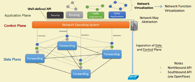

SDN introduces three-layer architecture with clean separation of concerns:
%%{init: {'theme': 'base', 'themeVariables': {'primaryColor':'#E8F4F8','primaryTextColor':'#2C3E50','primaryBorderColor':'#16A085','lineColor':'#16A085','secondaryColor':'#FEF5E7','tertiaryColor':'#FDEBD0','fontSize':'14px'}}}%%
graph TB
    subgraph ApplicationLayer["Application Layer"]
        direction LR
        App1["Traffic<br/>Engineering"]
        App2["Security<br/>Firewall"]
        App3["Load<br/>Balancer"]
        App4["Network<br/>Monitor"]
        App5["QoS<br/>Manager"]
    end

    subgraph ControlLayer["Control Layer"]
        Controller["SDN Controller<br/>(OpenDaylight, ONOS, Ryu)<br/>• Network Topology<br/>• Flow Computation<br/>• Device Management"]
    end

    subgraph DataLayer["Data/Infrastructure Layer"]
        direction LR
        SW1["OpenFlow<br/>Switch 1"]
        SW2["OpenFlow<br/>Switch 2"]
        SW3["OpenFlow<br/>Switch 3"]
        SW4["OpenFlow<br/>Switch 4"]
    end

    ApplicationLayer <-->|"Northbound API<br/>(REST, JSON-RPC)"| ControlLayer
    ControlLayer <-->|"Southbound API<br/>(OpenFlow Protocol)"| DataLayer

    SW1 <--> SW2
    SW2 <--> SW3
    SW3 <--> SW4

    style App1 fill:#E67E22,stroke:#2C3E50,color:#fff
    style App2 fill:#E67E22,stroke:#2C3E50,color:#fff
    style App3 fill:#E67E22,stroke:#2C3E50,color:#fff
    style App4 fill:#E67E22,stroke:#2C3E50,color:#fff
    style App5 fill:#E67E22,stroke:#2C3E50,color:#fff
    style Controller fill:#16A085,stroke:#2C3E50,color:#fff,stroke-width:3px
    style SW1 fill:#2C3E50,stroke:#16A085,color:#fff
    style SW2 fill:#2C3E50,stroke:#16A085,color:#fff
    style SW3 fill:#2C3E50,stroke:#16A085,color:#fff
    style SW4 fill:#2C3E50,stroke:#16A085,color:#fff
{fig-alt=“SDN three-layer architecture diagram showing application layer (traffic engineering, security, load balancing, monitoring, QoS) communicating via northbound REST APIs with control layer (SDN controller providing topology, flow computation, device management), which communicates via southbound OpenFlow protocol with data layer (interconnected OpenFlow switches)”}
278.6.1 Application Layer
Purpose: Network applications that define desired network behavior.
Applications: - Traffic Engineering: Optimize paths based on network conditions - Security: Firewall, IDS/IPS, DDoS mitigation - Load Balancing: Distribute traffic across servers - Network Monitoring: Real-time traffic analysis - QoS Management: Prioritize critical IoT traffic
Interface: Northbound APIs (REST, JSON-RPC, gRPC)
278.6.2 Control Layer (SDN Controller)
Purpose: Brain of the network—maintains global view and makes routing decisions.
Responsibilities: - Compute forwarding paths - Install flow rules in switches - Handle switch events (new flows, link failures) - Provide network state to applications - Maintain network topology
Popular Controllers: - OpenDaylight: Java-based, modular, widely adopted - ONOS: High availability, scalability for carriers - Ryu: Python-based, easy development - POX/NOX: Educational, Python/C++ - Floodlight: Java, fast performance
WarningTradeoff: Synchronous vs Asynchronous SDN Flow Installation
Option A (Synchronous / Blocking): Controller waits for switch acknowledgment before processing next flow. Guarantees flow is installed before returning success to application. Latency: 5-20ms per flow installation. Throughput: 50-200 flows/second per controller thread. Suitable for safety-critical applications requiring installation confirmation.
Option B (Asynchronous / Non-Blocking): Controller sends flow modification and continues immediately without waiting for acknowledgment. Higher throughput (1,000-10,000 flows/second), but application cannot confirm installation timing. Risk: packets may arrive before flow is installed, causing PACKET_IN storms or drops.
Decision Factors:
Choose Synchronous when: Flow installation must complete before traffic arrives (security quarantine, access control), application logic depends on flow state (load balancer needs confirmation before redirecting), or debugging requires deterministic flow timing. Accept 10x lower throughput for correctness guarantees.
Choose Asynchronous when: High flow churn (IoT device mobility, short-lived connections), controller is bottleneck (thousands of new flows/second), flows are best-effort (traffic engineering optimizations), or switches support reliable delivery with retries at OpenFlow layer.
Hybrid approach: Use asynchronous installation with barrier messages at critical points. Send batch of flows asynchronously, then send barrier request - switch replies only when all prior flows are installed. This achieves high throughput while providing synchronization when needed.
278.6.3 Data/Infrastructure Layer
Purpose: Packet forwarding based on flow rules installed by controller.
Components: - OpenFlow Switches: Hardware or software switches - Flow Tables: Store forwarding rules (match-action) - Secure Channel: Connection to controller (TLS)
Flow Processing: 1. Packet arrives at switch 2. Match against flow table 3. If match: execute action (forward, drop, modify) 4. If no match: send to controller (PACKET_IN)
NoteAlternative View: SDN Packet Decision Tree
This variant shows the decision process as a flowchart, helping students understand what happens when a packet enters an SDN switch.
%%{init: {'theme': 'base', 'themeVariables': {'primaryColor':'#2C3E50','primaryTextColor':'#fff','primaryBorderColor':'#16A085','lineColor':'#16A085','secondaryColor':'#E67E22','tertiaryColor':'#7F8C8D','fontSize':'14px'}}}%%
flowchart TB
    Start([Packet Arrives<br/>at Switch Port]) --> Lookup[Flow Table Lookup<br/>Match: src_ip, dst_ip,<br/>protocol, port]

    Lookup --> Match{Match<br/>Found?}

    Match -->|Yes| Priority[Select Highest<br/>Priority Rule]
    Priority --> Action[Execute Actions<br/>• Forward to port<br/>• Drop packet<br/>• Modify headers<br/>• Send to group]
    Action --> Counter[Update Counters<br/>• Packets: +1<br/>• Bytes: +packet_size]
    Counter --> Done([Packet Processed])

    Match -->|No| Buffer[Buffer Packet<br/>Store in switch memory]
    Buffer --> PacketIn[Send PACKET_IN<br/>to Controller]
    PacketIn --> Controller[Controller Processes<br/>• Calculate route<br/>• Generate flow rule]
    Controller --> FlowMod[Send FLOW_MOD<br/>Install new rule]
    FlowMod --> Install[Install Rule in<br/>Flow Table]
    Install --> Reprocess[Reprocess<br/>Buffered Packet]
    Reprocess --> Lookup

    style Start fill:#2C3E50,stroke:#16A085,color:#fff
    style Match fill:#E67E22,stroke:#2C3E50,color:#fff
    style Controller fill:#16A085,stroke:#2C3E50,color:#fff
    style Done fill:#2C3E50,stroke:#16A085,color:#fff
NoteAlternative View: Traditional vs SDN Side-by-Side
This variant directly compares traditional and SDN approaches for the same network change, quantifying the operational difference.
%%{init: {'theme': 'base', 'themeVariables': {'primaryColor':'#2C3E50','primaryTextColor':'#fff','primaryBorderColor':'#16A085','lineColor':'#16A085','secondaryColor':'#E67E22','tertiaryColor':'#7F8C8D','fontSize':'14px'}}}%%
flowchart LR
    subgraph Traditional["Traditional Network"]
        direction TB
        T_Admin["Network Admin"]
        T_S1["Switch 1<br/>SSH → CLI"]
        T_S2["Switch 2<br/>SSH → CLI"]
        T_S3["Switch 3<br/>SSH → CLI"]
        T_Dots["... 7 more ..."]

        T_Admin -->|"Manual config"| T_S1
        T_Admin -->|"Manual config"| T_S2
        T_Admin -->|"Manual config"| T_S3
        T_Admin -->|"Manual config"| T_Dots

        T_Time["Time: 2-4 hours<br/>Risk: Inconsistent state<br/>Rollback: Manual"]
    end

    subgraph SDN["SDN Network"]
        direction TB
        S_Admin["Network Admin"]
        S_Controller["SDN Controller"]
        S_S1["Switch 1"]
        S_S2["Switch 2"]
        S_S3["Switch 3"]
        S_Dots["... 7 more ..."]

        S_Admin -->|"1 API call"| S_Controller
        S_Controller -->|"Auto push"| S_S1
        S_Controller -->|"Auto push"| S_S2
        S_Controller -->|"Auto push"| S_S3
        S_Controller -->|"Auto push"| S_Dots

        S_Time["Time: 30 seconds<br/>Guaranteed: Consistent<br/>Rollback: Automatic"]
    end

    style T_Admin fill:#E67E22,stroke:#2C3E50,color:#fff
    style S_Admin fill:#16A085,stroke:#2C3E50,color:#fff
    style S_Controller fill:#16A085,stroke:#2C3E50,color:#fff
    style T_Time fill:#FDEBD0,stroke:#E67E22
    style S_Time fill:#D5F5E3,stroke:#16A085
NoteAlternative View: SDN Managing Smart Building IoT
This variant shows SDN controlling diverse IoT traffic in a smart building, demonstrating real-world application of QoS and network slicing.
%%{init: {'theme': 'base', 'themeVariables': {'primaryColor':'#2C3E50','primaryTextColor':'#fff','primaryBorderColor':'#16A085','lineColor':'#16A085','secondaryColor':'#E67E22','tertiaryColor':'#7F8C8D','fontSize':'12px'}}}%%
flowchart TB
    subgraph Building["Smart Building: 50 Floors"]
        subgraph Critical["Critical IoT (Fire/HVAC)"]
            Fire["Fire Sensors<br/>100 devices"]
            HVAC["HVAC Controls<br/>200 devices"]
        end

        subgraph Standard["Standard IoT"]
            Occupancy["Occupancy<br/>500 sensors"]
            Lighting["Lighting<br/>1000 fixtures"]
        end

        subgraph Bulk["Bulk Data"]
            Camera["Security Cameras<br/>200 cameras<br/>50 Mbps each"]
        end
    end

    Controller["SDN Controller<br/>QoS Policy Engine"]

    subgraph Network["Network Paths"]
        Path1["Slice 1: Critical<br/>Low latency <10ms<br/>Reserved 100 Mbps<br/>99.99% reliability"]
        Path2["Slice 2: Standard<br/>Best effort<br/>Shared bandwidth"]
        Path3["Slice 3: Video<br/>High bandwidth<br/>Traffic shaped"]
    end

    Cloud["Building Management<br/>Cloud Platform"]

    Critical --> Controller
    Standard --> Controller
    Bulk --> Controller

    Controller -->|"Priority: 1"| Path1
    Controller -->|"Priority: 3"| Path2
    Controller -->|"Priority: 2"| Path3

    Path1 --> Cloud
    Path2 --> Cloud
    Path3 --> Cloud

    style Critical fill:#E67E22,stroke:#2C3E50,color:#fff
    style Standard fill:#16A085,stroke:#2C3E50,color:#fff
    style Bulk fill:#2C3E50,stroke:#16A085,color:#fff
    style Controller fill:#16A085,stroke:#2C3E50,color:#fff
    style Path1 fill:#E67E22,stroke:#2C3E50,color:#fff
    style Path2 fill:#7F8C8D,stroke:#16A085,color:#fff
    style Path3 fill:#2C3E50,stroke:#16A085,color:#fff
WarningTradeoff: Microservices vs Monolithic SDN Controller Architecture
Option A (Monolithic Controller): Single deployable unit containing topology management, flow computation, device drivers, and northbound APIs. Simpler deployment, lower inter-service latency (in-process calls: <1ms), easier debugging with single log stream. Examples: Ryu, POX. Suitable for: campus networks (<500 switches), development/testing, small IoT deployments.
Option B (Microservices Controller): Independent services for topology, flow management, device drivers, statistics. Each service scales independently, enables polyglot development, and provides fault isolation. Inter-service latency: 2-10ms via REST/gRPC. Examples: ONOS (clustered), OpenDaylight (OSGi modular). Suitable for: carrier networks, multi-site deployments, high-availability requirements.
Decision Factors:
Choose Monolithic when: Network size is under 500 switches, team is small (1-3 developers), time-to-deployment is critical, or latency requirements demand sub-millisecond internal processing. Monolithic controllers handle 1,000-10,000 flows/second with consistent latency.
Choose Microservices when: Multiple teams need independent development cycles, different components have vastly different scaling needs (topology changes rarely, flow installations constantly), fault isolation is critical (device driver crash shouldn’t affect flow computation), or you need 99.99% availability with rolling updates.
Scaling limits: Monolithic ONOS handles ~500K flows and ~1,000 switches per instance. Beyond this, clustering (3-5 controllers with distributed state) is required. For IoT deployments with millions of devices, microservices architecture with dedicated flow processors becomes necessary. Migration path: start monolithic, refactor to microservices when hitting scale or team coordination limits.
278.7 Knowledge Check
Test your understanding of these architectural concepts.
278.8 Summary
This chapter introduced the fundamental concepts of Software-Defined Networking (SDN) architecture:
Key Takeaways:
Control/Data Plane Separation: SDN decouples decision-making (control plane) from packet forwarding (data plane), enabling centralized programmable network management
Three-Layer Architecture: Application layer (network apps), Control layer (SDN controller), and Data/Infrastructure layer (OpenFlow switches) with clean API separation
Traditional Network Limitations: Vendor lock-in, distributed control with no global view, static manual configuration, and inflexibility to application needs
SDN Benefits for IoT: Centralized management of thousands of devices, dynamic reconfiguration, diverse QoS policies, and improved security through network-wide visibility
Controller Role: Maintains global topology view, computes forwarding paths, installs flow rules, and provides network state to applications
Understanding these architectural fundamentals prepares you for deeper exploration of OpenFlow protocol details and SDN applications in IoT environments.
278.9 What’s Next?
Continue exploring SDN with the OpenFlow protocol details and flow table processing.