213 Processes & Systems: Core Definitions
213.1 Learning Objectives
By the end of this chapter, you will be able to:
- Define Process Concepts: Explain systems, processes, and input-output transformations in IoT
- Understand Block Diagrams: Represent complex electronic systems as interconnected components
- Decompose IoT Systems: Break down IoT systems into hardware, software, and network subsystems
- Analyze System Components: Identify inputs, outputs, processes, and constraints in IoT devices
- Apply Hierarchical Design: Use modular decomposition for debugging and optimization
213.2 Prerequisites
Before diving into this chapter, you should be familiar with:
- Sensor Fundamentals and Types: Understanding how sensors measure physical phenomena is essential for grasping how systems transform inputs into meaningful data
- Actuators: Knowledge of actuators helps understand how systems produce physical outputs in response to control signals
- IoT Reference Models: Familiarity with layered IoT architectures provides context for where processes operate within the device-to-cloud stack
213.3 Getting Started (For Beginners)
TipWhat Are Processes and Systems? (Simple Explanation)
Analogy: A process is like following a recipe—you have ingredients (inputs), cooking steps (the process), and a finished dish (output). A system is the entire kitchen setup that makes cooking possible.
Simple explanation: - Process: Any action that transforms inputs into outputs - System: A collection of parts working together toward a goal - Control: How you adjust the process to get the desired output
213.3.1 The Kitchen Analogy
NoteUnderstanding Systems Through Cooking
KITCHEN (System) - Baking a Cake:
| Component | Role | Examples |
|---|---|---|
| INPUTS | Raw materials & energy | Eggs, Milk, Flour, Butter, Electricity |
| PROCESS | Transformation | Mixing & Baking |
| OUTPUT | End product | Cake |
| CONTROL | Regulation | Temperature Setting |
Flow: INPUTS → PROCESS → OUTPUT (with CONTROL regulating the process)
Key insight: The temperature dial is your “control”—you adjust it to get the right output!
213.3.2 Self-Check Questions
Before diving into the technical details, test your understanding:
- Basic Concept: What’s the difference between a process and a system?
- Answer: A process is the transformation (input → output). A system is everything that makes it work together.
- Real-World: Can you identify the inputs, process, and outputs of a smart light bulb?
- Answer: Input: power + command signal. Process: interpret command, adjust LED driver. Output: light at specified brightness/color.
NoteKey Takeaway
In one sentence: Systems are collections of components that work together, while processes are the transformations that systems perform on inputs to produce outputs.
Remember this: Every IoT device can be analyzed as a system with inputs (sensors, user commands), processes (algorithms, logic), and outputs (actuators, displays, data).
213.4 What is a Process and What is a System?
⭐ Difficulty: Foundational
Most electronic systems, particularly IoT devices, are designed to perform specific tasks. These can be broken down into two fundamental components: the process and the system.
213.5 Key Definitions
- Process
- A series of actions or steps taken to achieve a particular end. In IoT devices, this is typically implemented by the program running on the microcontroller. The process defines how the device accomplishes its goal.
- System
- A set of things working together as parts of a mechanism or interconnecting network; a complex whole. In IoT, a system comprises the microcontroller, sensors, actuators, and their interactions working together to perform a specific function.
An electronic system is a physical interconnection of components that gathers information, processes it, and produces output. The sensors provide input, actuators provide output, and the microcontroller executes the process that transforms inputs into outputs.

Alternative View:
%%{init: {'theme': 'base', 'themeVariables': { 'primaryColor': '#2C3E50', 'primaryTextColor': '#fff', 'primaryBorderColor': '#16A085', 'lineColor': '#16A085', 'secondaryColor': '#E67E22', 'tertiaryColor': '#7F8C8D'}}}%%
flowchart TD
    START([System Receives<br/>Input Signal]) --> SENSE[Sensor Layer<br/>Measure physical value]

    SENSE --> CONVERT{Valid<br/>Reading?}

    CONVERT -->|Yes| PROCESS[Processing Layer<br/>Execute algorithm]
    CONVERT -->|No/Error| RETRY[Retry or<br/>Use default]
    RETRY --> SENSE

    PROCESS --> DECIDE{Output<br/>Required?}

    DECIDE -->|Yes| ACTUATE[Actuation Layer<br/>Drive output device]
    DECIDE -->|No change needed| WAIT[Wait for<br/>next cycle]

    ACTUATE --> FEEDBACK{Closed-Loop<br/>System?}

    FEEDBACK -->|Yes| MEASURE[Measure Output<br/>Compare to setpoint]
    FEEDBACK -->|No| COMPLETE([Cycle Complete])

    MEASURE --> ADJUST{Error<br/>Acceptable?}

    ADJUST -->|No| PROCESS
    ADJUST -->|Yes| COMPLETE

    WAIT --> START

    style START fill:#16A085,color:#fff
    style SENSE fill:#2C3E50,color:#fff
    style PROCESS fill:#2C3E50,color:#fff
    style ACTUATE fill:#E67E22,color:#fff
    style COMPLETE fill:#16A085,color:#fff
    style MEASURE fill:#7F8C8D,color:#fff
%%{init: {'theme': 'base', 'themeVariables': { 'primaryColor': '#2C3E50', 'primaryTextColor': '#fff', 'primaryBorderColor': '#16A085', 'lineColor': '#16A085', 'secondaryColor': '#E67E22', 'tertiaryColor': '#7F8C8D'}}}%%
graph TB
    subgraph Physical["Physical Layer"]
        direction LR
        ENV[Environment<br/>Temperature, Motion, Light]
        ACT[Physical Actions<br/>Movement, Heat, Sound]
    end

    subgraph Sensing["Sensing Layer"]
        direction LR
        SENS[Sensors<br/>Convert physical to electrical]
        TRANS[Transducers<br/>Signal conditioning]
    end

    subgraph Processing["Processing Layer"]
        direction LR
        ADC[ADC<br/>Analog to Digital]
        MCU[Microcontroller<br/>Algorithm execution]
        DAC[DAC<br/>Digital to Analog]
    end

    subgraph Control["Control Layer"]
        direction LR
        LOGIC[Control Logic<br/>Decision making]
        STATE[State Machine<br/>Mode management]
    end

    subgraph Actuation["Actuation Layer"]
        direction LR
        DRV[Drivers<br/>Power amplification]
        ACTS[Actuators<br/>Motors, valves, heaters]
    end

    ENV --> SENS
    SENS --> TRANS
    TRANS --> ADC
    ADC --> MCU
    MCU --> LOGIC
    LOGIC --> STATE
    STATE --> DAC
    DAC --> DRV
    DRV --> ACTS
    ACTS --> ACT
    ACT -.->|Feedback| ENV

    style Physical fill:#7F8C8D,color:#fff
    style Sensing fill:#16A085,color:#fff
    style Processing fill:#2C3E50,color:#fff
    style Control fill:#E67E22,color:#fff
    style Actuation fill:#16A085,color:#fff
213.6 Block Diagram Representation
⭐ Difficulty: Foundational

Complex electronic systems can be represented as interconnected “black boxes” where each box represents an individual component or subsystem. This block-diagram representation allows us to analyze systems at different levels of abstraction without getting overwhelmed by implementation details.
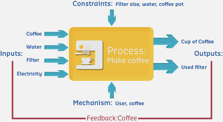
NoteExample: Coffee Pot System
Consider a simple coffee maker as an IoT-enabled system:

Inputs: - Ground coffee (material) - Water (material) - Filter (material) - Electricity (energy) - Start command (signal/control)
Process: - Heat water to optimal temperature (92-96°C) - Pump water through coffee grounds - Monitor temperature and flow rate - Execute brewing algorithm
Outputs: - Hot brewed coffee (primary output) - Status indicators (LEDs, mobile notifications) - Brewing completion signal
Constraints: - Physical size of coffee maker - Quantity of coffee and water available - Power consumption limits - Brewing time requirements
Mechanisms: - User must load filter with coffee - User must fill water reservoir - System must detect water level - Safety shutdown if reservoir empty
213.7 IoT System Decomposition
⭐⭐ Difficulty: Intermediate
Modern IoT systems can be decomposed into hierarchical blocks at multiple levels:

This hierarchical view helps engineers: - Identify component boundaries and interfaces - Isolate problems during debugging - Design modular, reusable subsystems - Optimize specific subsystem performance
TipCross-Hub Connections
Interactive Learning Tools: - Simulations Hub - Try the Network Topology Explorer to visualize how processes flow through different system architectures - Videos Hub - Watch process control demonstrations showing real systems in action - Quizzes Hub - Test your understanding of system decomposition and component interactions
Knowledge Resources: - Knowledge Gaps Hub - Common misconceptions about systems vs processes explained - Knowledge Map - See how processes & systems connect to sensors, actuators, and architectures
NoteRelated Chapters
This Series: - Processes & Systems: Control Types - Open-loop vs closed-loop control - Processes & Systems: PID Control - PID controller theory and applications
Deep Dives: - Process Control and PID - Advanced feedback control systems - Processes Labs and Review - Hands-on implementations
Foundation: - IoT Reference Models - System architecture layers - Architectural Enablers - IoT technology stack
Sensing & Actuation: - Sensor Fundamentals - Input devices - Actuators - Output devices
213.8 Summary
This chapter covered the core definitions of processes and systems in IoT:
- System Definition: Understanding systems as collections of interacting components that transform inputs into outputs with defined boundaries
- Process Definition: Recognizing processes as series of actions or steps that add value by transforming inputs (materials, energy, information) into outputs
- Block Diagram Representation: Using abstraction to represent complex IoT systems as interconnected black boxes for analysis at multiple levels
- Hierarchical Decomposition: Breaking down IoT systems into hardware, software, and network subsystems for modular design and debugging
- Input-Output Transformations: Analyzing how electronic systems gather information through sensors, process it via microcontrollers, and produce outputs through actuators
- Design Considerations: Evaluating input validation, process robustness, output verification, error propagation, and resource constraints
213.9 What’s Next
The next chapter explores Control Types: Open-Loop vs Closed-Loop, introducing the fundamental distinction between systems that operate without feedback and those that continuously measure and adjust based on output. You’ll learn how feedback mechanisms enable systems to self-regulate and maintain desired behaviors automatically.