268 Mobile Gateway Protocols and Hands-On Lab
268.1 Learning Objectives
By the end of this chapter, you will be able to:
- Understand MAC protocols: Apply CSMA/CA and MACAW for wireless medium access
- Identify terminal problems: Recognize hidden and exposed terminal scenarios
- Select communication technologies: Choose appropriate short-range and wide-area protocols
- Build an IoT gateway: Implement a working ESP32 gateway with protocol translation
268.2 Prerequisites
Before diving into this chapter, you should be familiar with:
- Mobile Gateway Fundamentals: Understanding basic gateway roles
- Mobile Computing Challenges: Knowledge of connectivity and resource constraints
- CSMA/CA: Carrier Sense Multiple Access with Collision Avoidance - wireless MAC protocol
- Hidden Terminal: Two transmitters can’t sense each other but collide at a common receiver
- Exposed Terminal: A transmitter unnecessarily defers when it could transmit safely
- RTS/CTS: Request-to-Send/Clear-to-Send handshaking to solve terminal problems
- NAV: Network Allocation Vector - timer for deferring transmission
268.3 Wireless Medium Access Control
Mobile devices must share the wireless medium efficiently to avoid collisions and maximize throughput. Understanding MAC protocols is crucial for mobile IoT implementations.
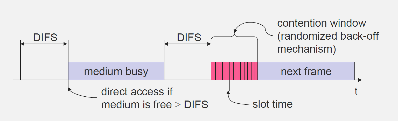
268.3.1 CSMA/CA: Carrier Sensing Multiple Access with Collision Avoidance
CSMA/CA is a network protocol used in wireless networks to reduce collisions. Before transmitting, a device senses the medium to determine if it’s free.
Operation: 1. Sense medium before transmitting 2. If free, transmit data 3. If busy, wait with exponential backoff 4. Retry when medium sensed free
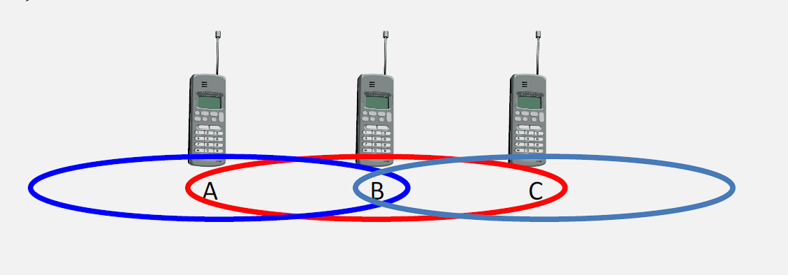
268.3.3 Exposed Terminal Problem
The exposed terminal problem occurs when a node refrains from transmitting even though it could do so without causing interference.
Scenario: - Node B transmits to Node A - Node C wants to transmit to Node D (different receiver) - C senses medium busy and waits - But A is outside C’s range, so C could transmit safely - C is unnecessarily “exposed” to B’s transmission

268.3.4 MACAW Protocol: Multiple Access with Collision Avoidance for Wireless
MACAW extends basic CSMA/CA with RTS/CTS handshaking to address hidden and exposed terminal problems.
Operation: 1. Sender transmits Request to Send (RTS) 2. Receiver responds with Clear to Send (CTS) 3. Other nodes overhear RTS or CTS and defer transmission 4. Information stored in Network Allocation Vector (NAV) 5. Sender transmits data 6. Receiver sends ACK
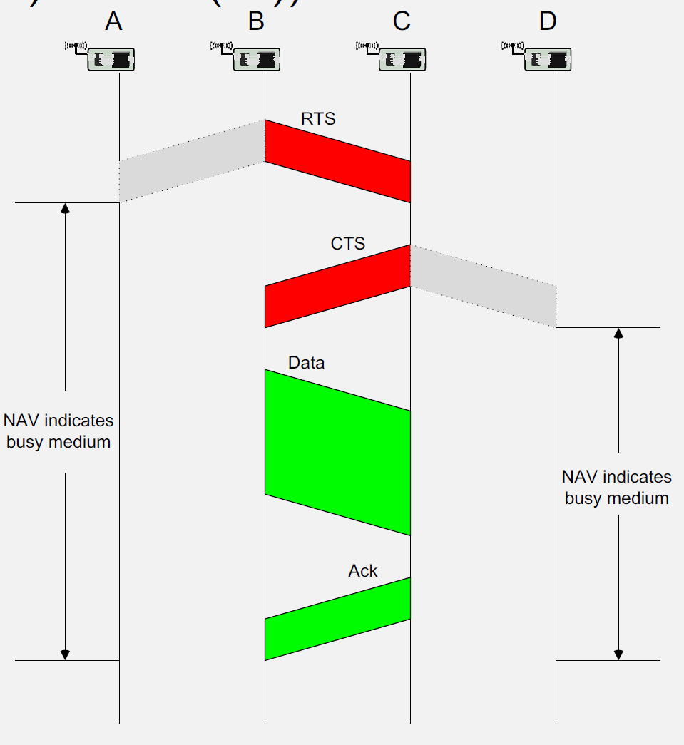
Used in: IEEE 802.11 (Wi-Fi) and many wireless protocols
268.4 Mobile Phone Communication Technologies
Mobile phones support multiple communication technologies, each suited to different IoT scenarios.
268.4.1 Short-Range Technologies
Bluetooth/Bluetooth Low Energy (BLE): - Range: 10-100 meters - Power: Very low (BLE) - Use Cases: Wearables, smart home devices, beacons - Data Rate: 1-3 Mbps
Near Field Communication (NFC): - Range: < 10 cm - Power: Passive tags require no power - Use Cases: Payments, access control, device pairing - Data Rate: 424 Kbps
Wi-Fi Direct: - Range: 50-200 meters - Power: Moderate to high - Use Cases: Direct file transfer, screen mirroring, printer connectivity - Data Rate: Up to several hundred Mbps
268.4.2 Wide-Area Technologies
Cellular (4G/5G): - Range: Kilometers - Power: Moderate to high - Use Cases: Vehicle tracking, remote monitoring, mobile applications - Data Rate: Mbps to Gbps
NB-IoT/LTE-M: - Range: Kilometers - Power: Low (optimized for IoT) - Use Cases: Smart meters, asset tracking, agricultural monitoring - Data Rate: Kbps
268.5 Best Practices for Mobile Phone-Based IoT
268.5.1 Energy Management
- Implement adaptive duty cycling based on context
- Use push notifications instead of polling
- Batch network transmissions
- Leverage low-power communication protocols (BLE)
- Optimize background task execution
268.5.2 Connectivity Optimization
- Implement offline capabilities with synchronization
- Use local caching to reduce network requests
- Compress data before transmission
- Adapt quality based on network conditions
- Provide connectivity status feedback to users
268.5.3 Security Implementation
- Encrypt all data transmissions
- Implement certificate-based authentication
- Use secure storage for sensitive data
- Regular security updates and patches
- User education on security best practices
268.5.4 User Experience
- Design for one-handed operation
- Provide clear status indicators
- Minimize user intervention (automation)
- Graceful degradation when features unavailable
- Responsive design for various screen sizes
268.6 Hands-On Lab: Building an IoT Gateway
268.6.1 Learning Objectives
By completing this hands-on lab, you will be able to:
- Configure ESP32 as an IoT gateway that bridges sensor nodes with cloud services
- Implement serial-based sensor data reception simulating BLE/Zigbee sensor nodes
- Aggregate and process sensor data before cloud transmission
- Transmit data via MQTT protocol to a cloud broker
- Apply gateway design patterns including buffering, validation, and protocol translation
268.6.2 Prerequisites
Before starting this lab:
- Basic familiarity with Arduino/C++ programming
- Understanding of MQTT protocol concepts (see MQTT chapter)
- Web browser with internet access
268.6.3 Lab Environment: Wokwi ESP32 Simulator
Wokwi is a free online electronics simulator that allows you to prototype IoT projects without physical hardware. The embedded simulator below provides a pre-configured ESP32 development environment.
- Click inside the simulator frame below to activate it
- The code editor appears on the left, circuit diagram on the right
- Click the green Play button to start the simulation
- Use the Serial Monitor tab to interact with the gateway
- You can modify the code and re-run to experiment
268.6.4 Step-by-Step Instructions
268.6.4.1 Step 1: Understanding the Gateway Architecture
Before writing code, understand what we’re building:
┌─────────────────┐     ┌─────────────────┐     ┌─────────────────┐
│  Sensor Nodes   │     │   ESP32 Gateway │     │   Cloud/MQTT    │
│  (Simulated)    │────▶│   - Receive     │────▶│   Broker        │
│                 │     │   - Validate    │     │                 │
│  Temperature    │     │   - Aggregate   │     │  HiveMQ Public  │
│  Humidity       │     │   - Transmit    │     │  broker.hivemq  │
│  Pressure       │     │                 │     │  .com           │
└─────────────────┘     └─────────────────┘     └─────────────────┘
In this lab, we simulate sensor nodes by sending data through the Serial Monitor. In a real deployment, this would be Bluetooth LE, Zigbee, or another short-range protocol.
268.6.4.2 Step 2: Copy the Gateway Code
Copy the following code into the Wokwi editor (replace all existing code):
/*
 * ESP32 IoT Gateway Lab
 * Demonstrates gateway functions: receive, validate, aggregate, transmit
 *
 * Protocol Translation: Serial (simulating BLE) -> MQTT over Wi-Fi
 *
 * Simulated sensor input format (via Serial Monitor):
 *   SENSOR:node_id:type:value
 *   Example: SENSOR:node1:temp:23.5
 *            SENSOR:node2:humidity:65.0
 *            SENSOR:node3:pressure:1013.25
 */

#include <WiFi.h>
#include <PubSubClient.h>
#include <ArduinoJson.h>

// ============== Configuration ==============
// Note: In Wokwi simulation, use these test credentials
const char* WIFI_SSID = "Wokwi-GUEST";
const char* WIFI_PASS = "";

// Public MQTT broker for testing (no authentication required)
const char* MQTT_BROKER = "broker.hivemq.com";
const int MQTT_PORT = 1883;
const char* MQTT_CLIENT_ID = "esp32_gateway_lab";
const char* MQTT_TOPIC_BASE = "iot/gateway/lab";

// Gateway configuration
const int MAX_SENSORS = 10;
const unsigned long AGGREGATION_INTERVAL = 10000; // 10 seconds
const unsigned long HEARTBEAT_INTERVAL = 30000;   // 30 seconds

// ============== Data Structures ==============
struct SensorReading {
  String nodeId;
  String sensorType;
  float value;
  unsigned long timestamp;
  bool valid;
};

struct AggregatedData {
  String nodeId;
  String sensorType;
  float minValue;
  float maxValue;
  float sumValue;
  int count;
};

// ============== Global Variables ==============
WiFiClient espClient;
PubSubClient mqttClient(espClient);

SensorReading sensorBuffer[MAX_SENSORS];
int bufferIndex = 0;

unsigned long lastAggregationTime = 0;
unsigned long lastHeartbeatTime = 0;
int messagesReceived = 0;
int messagesTransmitted = 0;

// ============== Setup ==============
void setup() {
  Serial.begin(115200);
  delay(1000);

  printBanner();

  // Connect to Wi-Fi
  connectWiFi();

  // Configure MQTT
  mqttClient.setServer(MQTT_BROKER, MQTT_PORT);
  mqttClient.setCallback(mqttCallback);

  // Connect to MQTT broker
  connectMQTT();

  printInstructions();
}

// ============== Main Loop ==============
void loop() {
  // Maintain MQTT connection
  if (!mqttClient.connected()) {
    connectMQTT();
  }
  mqttClient.loop();

  // Check for incoming sensor data (simulated via Serial)
  if (Serial.available()) {
    String input = Serial.readStringUntil('\n');
    input.trim();
    processSensorInput(input);
  }

  // Periodic aggregation and transmission
  unsigned long currentTime = millis();

  if (currentTime - lastAggregationTime >= AGGREGATION_INTERVAL) {
    aggregateAndTransmit();
    lastAggregationTime = currentTime;
  }

  // Heartbeat message
  if (currentTime - lastHeartbeatTime >= HEARTBEAT_INTERVAL) {
    sendHeartbeat();
    lastHeartbeatTime = currentTime;
  }
}

// ============== Gateway Functions ==============

void processSensorInput(String input) {
  Serial.println("\n[GATEWAY] Received: " + input);

  // Parse input: SENSOR:node_id:type:value
  if (!input.startsWith("SENSOR:")) {
    if (input == "STATUS") {
      printStatus();
    } else if (input == "FLUSH") {
      aggregateAndTransmit();
    } else if (input == "HELP") {
      printInstructions();
    } else {
      Serial.println("[ERROR] Invalid format. Use: SENSOR:node_id:type:value");
    }
    return;
  }

  // Protocol Translation: Parse sensor data
  SensorReading reading = parseSensorData(input);

  if (reading.valid) {
    // Data Validation
    if (validateReading(reading)) {
      // Buffer for aggregation
      addToBuffer(reading);
      messagesReceived++;
      Serial.printf("[OK] Buffered: %s/%s = %.2f\n",
                    reading.nodeId.c_str(),
                    reading.sensorType.c_str(),
                    reading.value);
    } else {
      Serial.println("[REJECTED] Value out of valid range");
    }
  } else {
    Serial.println("[ERROR] Failed to parse sensor data");
  }
}

SensorReading parseSensorData(String input) {
  SensorReading reading;
  reading.valid = false;
  reading.timestamp = millis();

  // Split by colon: SENSOR:node_id:type:value
  int idx1 = input.indexOf(':', 0);
  int idx2 = input.indexOf(':', idx1 + 1);
  int idx3 = input.indexOf(':', idx2 + 1);

  if (idx1 > 0 && idx2 > idx1 && idx3 > idx2) {
    reading.nodeId = input.substring(idx1 + 1, idx2);
    reading.sensorType = input.substring(idx2 + 1, idx3);
    reading.value = input.substring(idx3 + 1).toFloat();
    reading.valid = true;
  }

  return reading;
}

bool validateReading(SensorReading& reading) {
  // Data Validation: Check value ranges based on sensor type
  if (reading.sensorType == "temp") {
    // Temperature: -40C to 85C (typical sensor range)
    return (reading.value >= -40.0 && reading.value <= 85.0);
  }
  else if (reading.sensorType == "humidity") {
    // Humidity: 0% to 100%
    return (reading.value >= 0.0 && reading.value <= 100.0);
  }
  else if (reading.sensorType == "pressure") {
    // Pressure: 300 to 1100 hPa
    return (reading.value >= 300.0 && reading.value <= 1100.0);
  }
  else if (reading.sensorType == "light") {
    // Light: 0 to 100000 lux
    return (reading.value >= 0.0 && reading.value <= 100000.0);
  }

  // Unknown sensor type - accept but warn
  Serial.println("[WARN] Unknown sensor type, accepting value");
  return true;
}

void addToBuffer(SensorReading& reading) {
  if (bufferIndex < MAX_SENSORS) {
    sensorBuffer[bufferIndex++] = reading;
  } else {
    // Buffer full - force transmission
    Serial.println("[WARN] Buffer full, forcing transmission");
    aggregateAndTransmit();
    sensorBuffer[0] = reading;
    bufferIndex = 1;
  }
}

void aggregateAndTransmit() {
  if (bufferIndex == 0) {
    Serial.println("\n[GATEWAY] No data to aggregate");
    return;
  }

  Serial.printf("\n[GATEWAY] Aggregating %d readings...\n", bufferIndex);

  // Create JSON document for aggregated data
  StaticJsonDocument<1024> doc;
  doc["gateway_id"] = MQTT_CLIENT_ID;
  doc["timestamp"] = millis();
  doc["reading_count"] = bufferIndex;

  JsonArray sensors = doc.createNestedArray("sensors");

  // Simple aggregation: group by node_id and sensor_type
  // In production, implement proper aggregation with min/max/avg
  for (int i = 0; i < bufferIndex; i++) {
    JsonObject sensor = sensors.createNestedObject();
    sensor["node"] = sensorBuffer[i].nodeId;
    sensor["type"] = sensorBuffer[i].sensorType;
    sensor["value"] = sensorBuffer[i].value;
    sensor["ts"] = sensorBuffer[i].timestamp;
  }

  // Serialize to JSON string
  String jsonString;
  serializeJson(doc, jsonString);

  // Construct topic: iot/gateway/lab/data
  String topic = String(MQTT_TOPIC_BASE) + "/data";

  // Transmit via MQTT
  Serial.println("[TRANSMIT] Publishing to: " + topic);
  Serial.println("[PAYLOAD] " + jsonString);

  if (mqttClient.publish(topic.c_str(), jsonString.c_str())) {
    messagesTransmitted++;
    Serial.printf("[OK] Published successfully (%d total)\n", messagesTransmitted);
  } else {
    Serial.println("[ERROR] MQTT publish failed");
  }

  // Clear buffer
  bufferIndex = 0;
}

void sendHeartbeat() {
  StaticJsonDocument<256> doc;
  doc["gateway_id"] = MQTT_CLIENT_ID;
  doc["uptime_ms"] = millis();
  doc["msgs_received"] = messagesReceived;
  doc["msgs_transmitted"] = messagesTransmitted;
  doc["wifi_rssi"] = WiFi.RSSI();
  doc["free_heap"] = ESP.getFreeHeap();

  String jsonString;
  serializeJson(doc, jsonString);

  String topic = String(MQTT_TOPIC_BASE) + "/heartbeat";
  mqttClient.publish(topic.c_str(), jsonString.c_str());

  Serial.println("\n[HEARTBEAT] Gateway status published");
}

// ============== Connectivity Functions ==============

void connectWiFi() {
  Serial.print("[WiFi] Connecting to ");
  Serial.println(WIFI_SSID);

  WiFi.begin(WIFI_SSID, WIFI_PASS);

  int attempts = 0;
  while (WiFi.status() != WL_CONNECTED && attempts < 20) {
    delay(500);
    Serial.print(".");
    attempts++;
  }

  if (WiFi.status() == WL_CONNECTED) {
    Serial.println("\n[WiFi] Connected!");
    Serial.print("[WiFi] IP Address: ");
    Serial.println(WiFi.localIP());
  } else {
    Serial.println("\n[WiFi] Connection failed - continuing in offline mode");
  }
}

void connectMQTT() {
  Serial.print("[MQTT] Connecting to broker...");

  int attempts = 0;
  while (!mqttClient.connected() && attempts < 5) {
    if (mqttClient.connect(MQTT_CLIENT_ID)) {
      Serial.println(" Connected!");

      // Subscribe to command topic
      String cmdTopic = String(MQTT_TOPIC_BASE) + "/commands";
      mqttClient.subscribe(cmdTopic.c_str());
      Serial.println("[MQTT] Subscribed to: " + cmdTopic);

      // Publish online status
      String statusTopic = String(MQTT_TOPIC_BASE) + "/status";
      mqttClient.publish(statusTopic.c_str(), "online");

    } else {
      Serial.print(".");
      delay(1000);
      attempts++;
    }
  }

  if (!mqttClient.connected()) {
    Serial.println("\n[MQTT] Connection failed - check broker settings");
  }
}

void mqttCallback(char* topic, byte* payload, unsigned int length) {
  Serial.print("\n[MQTT] Message received on topic: ");
  Serial.println(topic);

  String message;
  for (unsigned int i = 0; i < length; i++) {
    message += (char)payload[i];
  }
  Serial.println("[MQTT] Payload: " + message);

  // Handle commands from cloud
  if (message == "FLUSH") {
    Serial.println("[CMD] Executing flush command from cloud");
    aggregateAndTransmit();
  } else if (message == "STATUS") {
    sendHeartbeat();
  }
}

// ============== Utility Functions ==============

void printBanner() {
  Serial.println("\n");
  Serial.println("==============================");
  Serial.println("  ESP32 IoT Gateway Lab");
  Serial.println("  Wokwi Edition");
  Serial.println("");
  Serial.println("  Gateway Functions:");
  Serial.println("  - Protocol Translation");
  Serial.println("  - Data Validation");
  Serial.println("  - Aggregation");
  Serial.println("  - Cloud Connectivity");
  Serial.println("==============================");
  Serial.println();
}

void printInstructions() {
  Serial.println("\n========== INSTRUCTIONS ==========");
  Serial.println("Simulate sensor nodes by typing in Serial Monitor:");
  Serial.println();
  Serial.println("Format: SENSOR:node_id:type:value");
  Serial.println();
  Serial.println("Examples:");
  Serial.println("  SENSOR:node1:temp:23.5");
  Serial.println("  SENSOR:node2:humidity:65.0");
  Serial.println("  SENSOR:node3:pressure:1013.25");
  Serial.println("  SENSOR:outdoor:light:850.0");
  Serial.println();
  Serial.println("Commands:");
  Serial.println("  STATUS - Show gateway statistics");
  Serial.println("  FLUSH  - Force immediate transmission");
  Serial.println("  HELP   - Show this help message");
  Serial.println();
  Serial.println("Data aggregates every 10 seconds.");
  Serial.println("===================================\n");
}

void printStatus() {
  Serial.println("\n========== GATEWAY STATUS ==========");
  Serial.printf("Uptime: %lu ms\n", millis());
  Serial.printf("Messages Received: %d\n", messagesReceived);
  Serial.printf("Messages Transmitted: %d\n", messagesTransmitted);
  Serial.printf("Buffer Usage: %d/%d\n", bufferIndex, MAX_SENSORS);
  Serial.printf("WiFi Status: %s\n", WiFi.status() == WL_CONNECTED ? "Connected" : "Disconnected");
  Serial.printf("WiFi RSSI: %d dBm\n", WiFi.RSSI());
  Serial.printf("MQTT Status: %s\n", mqttClient.connected() ? "Connected" : "Disconnected");
  Serial.printf("Free Heap: %d bytes\n", ESP.getFreeHeap());
  Serial.println("=====================================\n");
}
268.6.4.3 Step 3: Run the Simulation
- Click the green Play button in the Wokwi toolbar
- Wait for the ESP32 to boot and connect to Wi-Fi (simulated)
- Observe the startup messages in the Serial Monitor
You should see output like:
==============================
  ESP32 IoT Gateway Lab
...
[WiFi] Connected!
[WiFi] IP Address: 10.10.0.2
[MQTT] Connecting to broker... Connected!
268.6.4.4 Step 4: Send Simulated Sensor Data
In the Serial Monitor input field, type sensor readings to simulate data from IoT nodes:
SENSOR:kitchen:temp:22.5
SENSOR:bedroom:temp:21.0
SENSOR:bathroom:humidity:78.5
SENSOR:outdoor:pressure:1015.2
Each reading demonstrates the gateway’s core functions:
- Protocol Translation: Serial input (simulating BLE) parsed and converted to JSON
- Validation: Values checked against acceptable ranges (e.g., temperature -40 to 85C)
- Buffering: Readings stored until aggregation interval
268.6.4.5 Step 5: Observe Aggregation
After 10 seconds (or type FLUSH), watch the gateway aggregate and transmit:
[GATEWAY] Aggregating 4 readings...
[TRANSMIT] Publishing to: iot/gateway/lab/data
[PAYLOAD] {"gateway_id":"esp32_gateway_lab","timestamp":15234,
           "reading_count":4,"sensors":[...]}
[OK] Published successfully (1 total)
268.6.4.6 Step 6: Test Edge Cases
Try these scenarios to understand gateway behavior:
Invalid data format:
BADDATA123Expected: [ERROR] Invalid format. Use: SENSOR:node_id:type:value
Out-of-range values:
SENSOR:test:temp:150.0Expected: [REJECTED] Value out of valid range (temperature max is 85C)
Check gateway status:
STATUSShows uptime, message counts, buffer usage, and connection status.
268.6.5 Challenge Exercises
Modify the aggregateAndTransmit() function to calculate a moving average for each sensor type instead of sending raw values. This demonstrates edge processing - reducing data before cloud transmission.
Hint: Create a separate aggregation structure that tracks min, max, sum, and count for each node/sensor combination.
Add threshold-based anomaly detection to the gateway. When a temperature exceeds 30C or humidity exceeds 90%, immediately publish an alert to a separate topic: iot/gateway/lab/alerts.
Hint: Add a checkForAnomalies() function called within processSensorInput() that bypasses the buffer for critical alerts.
Modify the code to continue buffering data when MQTT is disconnected, then transmit all buffered data when connectivity resumes. Implement a larger buffer (100 readings) for this store-and-forward pattern.
Hint: Check mqttClient.connected() before publishing, and expand the buffer size. Consider using SPIFFS for persistent storage.
Extend the gateway to accept multiple input formats: - SENSOR:node:type:value (current format) - JSON:{"node":"id","type":"temp","value":23.5} (JSON format) - CSV:node,type,value (CSV format)
This demonstrates protocol translation from multiple source protocols to a unified MQTT output.
268.6.6 Lab Summary
In this lab, you implemented a functional IoT gateway that demonstrates:
| Gateway Function | Implementation |
|---|---|
| Protocol Translation | Serial input → JSON → MQTT |
| Data Validation | Range checking per sensor type |
| Aggregation | Buffer readings, transmit periodically |
| Cloud Connectivity | MQTT publish to HiveMQ broker |
| Status Monitoring | Heartbeat messages with diagnostics |
| Command Reception | Subscribe to cloud commands |
In production deployments, replace the Serial input simulation with actual sensor protocols:
- BLE: Use ESP32’s Bluetooth to receive data from BLE sensors (heart rate monitors, environmental sensors)
- Zigbee: Add a Zigbee coordinator module to receive data from Zigbee mesh networks
- LoRa: Connect a LoRa radio to receive data from long-range sensor nodes
- Modbus: Use RS-485 interface for industrial sensor connectivity
The gateway architecture remains the same - only the input protocol handling changes.
268.7 Visual Reference Gallery


268.8 Summary
This chapter covered MAC protocols, communication technologies, and hands-on gateway implementation:
- CSMA/CA: Wireless MAC protocol using carrier sensing and exponential backoff to avoid collisions
- Hidden/Exposed Terminal: Problems where nodes can’t properly sense channel occupancy; solved by RTS/CTS handshaking (MACAW)
- Communication Technologies: Short-range (BLE 10-100m, NFC <10cm, Wi-Fi Direct 50-200m) and wide-area (4G/5G kilometers, NB-IoT/LTE-M)
- Best Practices: Duty cycling for energy, store-and-forward for connectivity, encryption for security, responsive design for UX
- Gateway Lab: Implemented ESP32 gateway with protocol translation (Serial→JSON→MQTT), data validation, aggregation, and cloud connectivity
Deep Dives: - M2M Communication - Gateway protocols and device management - Edge-Fog Computing - Mobile phones as fog nodes - Mobile as Sensor - Smartphone sensor capabilities
Protocols: - Bluetooth Fundamentals - BLE for sensor connectivity - MQTT Protocol - Cloud gateway communication - Wi-Fi Architecture - Wi-Fi gateway connectivity
Architecture: - IoT Reference Models - Gateway layer in 7-level architecture - Wireless Sensor Networks - WSN gateway patterns
Learning: - Videos Hub - Mobile gateway demonstrations - Simulations Hub - Gateway protocol simulators
268.9 What’s Next?
Having explored mobile phones as IoT gateways, we now examine Wireless Sensor Networks. The next chapter builds upon these foundations to explore additional architectural patterns and considerations.