%% fig-alt: "FANET-VANET integration architecture: Aerial layer with 3 UAVs (UAV 1 traffic monitor at 150m, UAV 2 relay at 200m, UAV 3 emergency response at 120m) forming FANET links; Ground layer with 4 vehicles traveling 70-100 km/h forming VANET links; UAV-to-vehicle air-to-ground communication for monitoring, emergency alerts, coverage extension; Infrastructure includes ground control station, roadside unit, traffic management cloud; Five use cases: coverage extension in rural areas, traffic monitoring for congestion, emergency response for accidents, connectivity bridge for disconnected segments, real-time rerouting; Challenges: dual high mobility of UAVs and vehicles, air-to-ground propagation complexity, 3D topology meeting 2D road constraints, protocol heterogeneity, handoff complexity"
%%{init: {'theme': 'base', 'themeVariables': {'primaryColor': '#2C3E50', 'primaryTextColor': '#fff', 'primaryBorderColor': '#16A085', 'lineColor': '#E67E22', 'secondaryColor': '#ECF0F1', 'tertiaryColor': '#fff', 'nodeTextColor': '#2C3E50'}}}%%
graph TB
    subgraph "FANET-VANET Integration Scenarios"
        subgraph "Aerial Layer (UAVs - FANET)"
            UAV1["UAV 1<br/>Traffic Monitor<br/>Altitude: 150m"]
            UAV2["UAV 2<br/>Relay Node<br/>Altitude: 200m"]
            UAV3["UAV 3<br/>Emergency Response<br/>Altitude: 120m"]

            UAV1 <-.->|FANET Link| UAV2
            UAV2 <-.->|FANET Link| UAV3
        end

        subgraph "Ground Layer (Vehicles - VANET)"
            V1["Vehicle 1<br/>Emergency<br/>100 km/h"]
            V2["Vehicle 2<br/>Normal Traffic<br/>80 km/h"]
            V3["Vehicle 3<br/>Normal Traffic<br/>90 km/h"]
            V4["Vehicle 4<br/>Connected Car<br/>70 km/h"]

            V1 <-.->|VANET Link| V2
            V2 <-.->|VANET Link| V3
            V3 <-.->|VANET Link| V4
        end

        subgraph "Infrastructure"
            GCS["Ground Control<br/>Station"]
            RSU["Roadside Unit<br/>(RSU)"]
            Cloud["Traffic Management<br/>Cloud"]
        end

        UAV1 -->|Traffic Data| Cloud
        UAV2 -->|Relay| GCS
        UAV3 -->|Emergency Alert| V1

        UAV1 -.->|Air-to-Ground| V2
        UAV1 -.->|Monitor| V3
        UAV2 -.->|Coverage Extension| V4

        RSU <-->|Wired| Cloud
        GCS <-->|Wired| Cloud

        UseCases["Use Cases:<br/>1. Coverage Extension (rural areas)<br/>2. Traffic Monitoring (congestion detection)<br/>3. Emergency Response (accident alerts)<br/>4. Connectivity Bridge (disconnected segments)<br/>5. Real-time Rerouting"]

        Challenges["Challenges:<br/>• Dual high mobility (UAV + vehicle)<br/>• Air-to-ground propagation<br/>• 3D topology + 2D road constraints<br/>• Protocol heterogeneity<br/>• Handoff complexity"]
    end

    UseCases -.->|Enable| UAV1
    Challenges -.->|Impact| UAV2

    style UAV1 fill:#E67E22,stroke:#2C3E50,color:#fff
    style V1 fill:#16A085,stroke:#2C3E50,color:#fff
    style Cloud fill:#2C3E50,stroke:#16A085,color:#fff
    style UseCases fill:#16A085,stroke:#2C3E50,color:#fff
    style Challenges fill:#7F8C8D,stroke:#2C3E50,color:#fff
453 FANET-VANET Integration and Ground Networks
453.1 Learning Objectives
By the end of this chapter, you will be able to:
- Design FANET-VANET Systems: Architect integrated UAV and vehicular networks for traffic monitoring and emergency response
- Handle Dual Mobility: Address challenges of both UAVs and vehicles moving at high speeds simultaneously
- Implement Position-Based Routing: Apply geographic routing algorithms with energy-aware optimization in 3D space
- Plan Multi-Layer Deployments: Design altitude-stratified FANET architectures for highway and urban coverage
453.2 Prerequisites
Before diving into this chapter, you should be familiar with:
- FANET Fundamentals: Understanding FANET architecture, 3D topology, and routing challenges provides the foundation for integration scenarios
- FANET Gateway Selection: Knowledge of gateway algorithms helps understand how FANETs connect to ground infrastructure
- UAV Networks: Fundamentals and Topologies: Basic UAV networking concepts are essential for understanding air-to-ground communication
- Networking Basics: Core networking and routing concepts apply to both aerial and vehicular networks
453.3 FANET-VANET Integration
TipFor Beginners: Drones Helping Cars
Imagine drones flying above a highway, watching traffic and helping cars communicate. This is FANET-VANET integration.
FANET: Flying drones forming a network in the air VANET: Cars on the road forming a network
Why combine them? - Drones see traffic from above (detect accidents, congestion) - Drones relay messages when cars are too far apart - Drones provide coverage in areas without cell towers
Example scenario: Accident on highway. No cell coverage in rural area. 1. Nearby car detects accident (airbag deployment, sudden stop) 2. Car sends alert to drone overhead 3. Drone relays to other drones in chain 4. Eventually reaches drone with cell coverage 5. Emergency services notified within seconds
The challenge: Both drones and cars are moving fast! A drone at 15 m/s and a car at 30 m/s (100 km/h) can have relative speed of 45 m/s. Communication links change constantly.
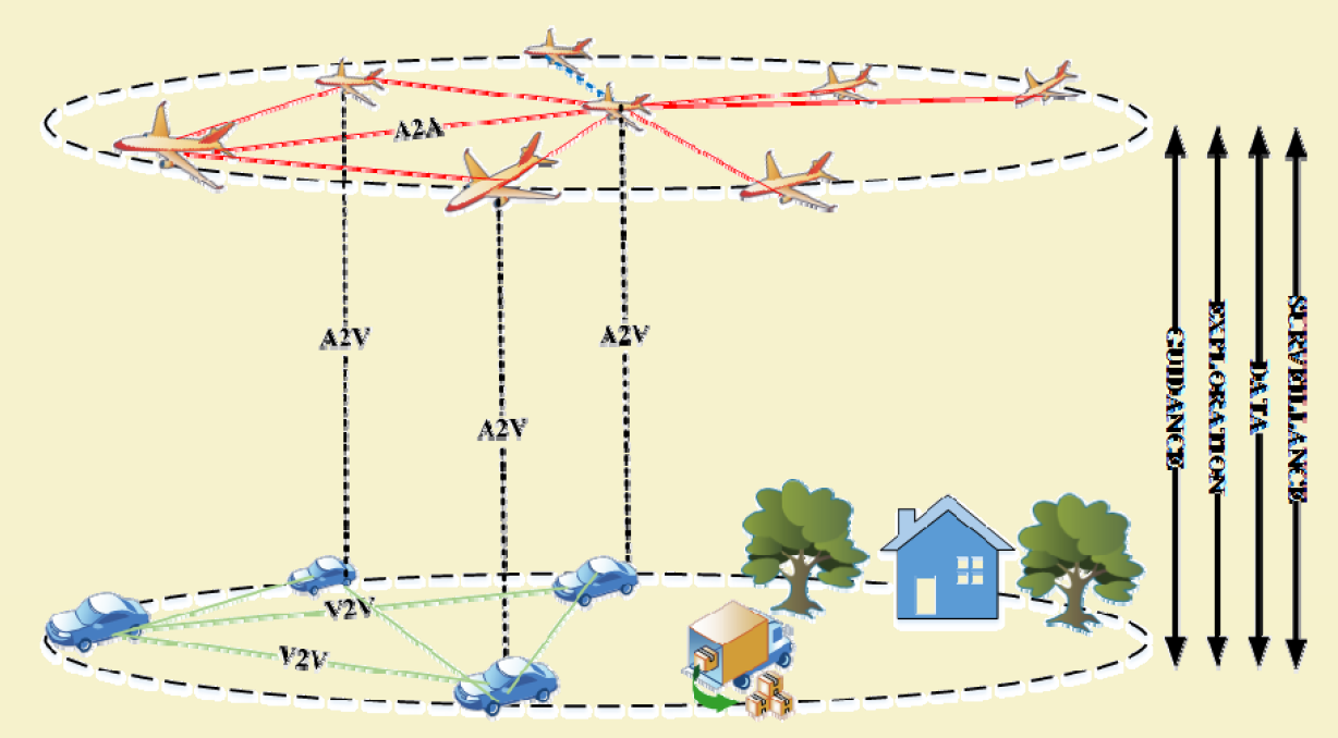
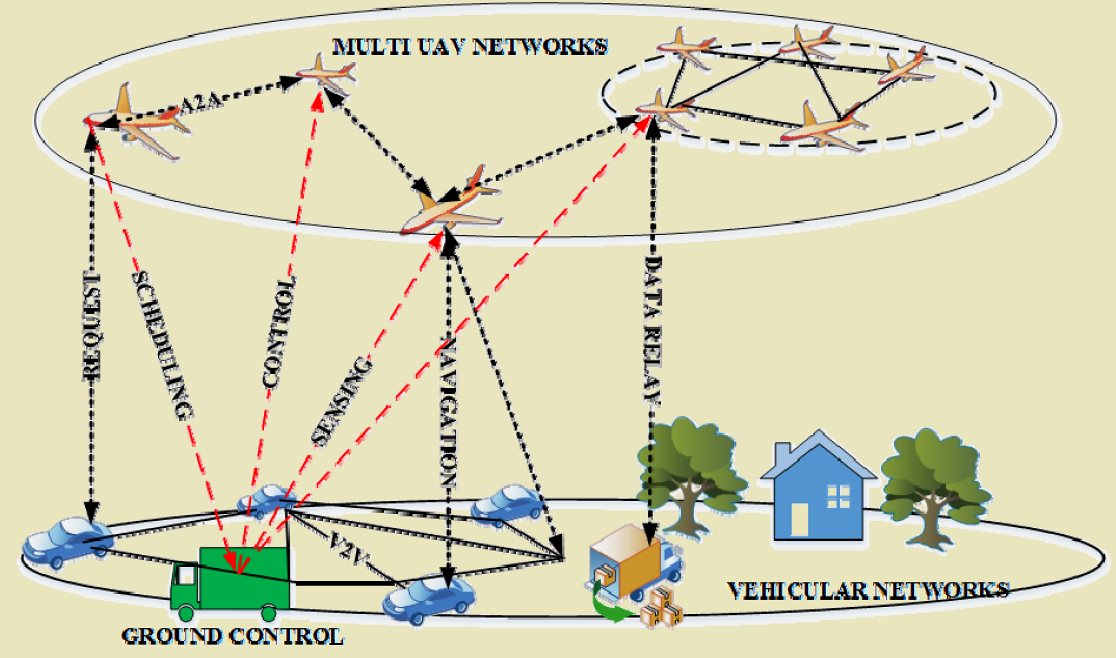
UAVs can provide aerial support for vehicular networks, enhancing coverage, connectivity, and safety.
453.4 Integration Use Cases
1. Coverage Extension - UAVs relay messages in areas without infrastructure - Temporary coverage during events or emergencies - Bridge connectivity gaps in rural highways
2. Traffic Monitoring - Aerial surveillance and congestion detection - Real-time traffic flow optimization - Incident detection from above
3. Emergency Response - Accident detection and alert dissemination - Guide emergency vehicles through traffic - Provide communication when ground infrastructure damaged
4. Connectivity Improvement - Bridge disconnected VANET segments - Reduce packet loss in sparse networks - Provide alternative paths during congestion
453.5 Position-Based Routing in 3D FANET
Geographic routing is critical for FANET-VANET integration where topology changes rapidly.
NoteWorked Example: Position-Based Routing Decision in 3D FANET
Scenario: A UAV at position (500, 300, 150) needs to forward a packet to destination (2000, 1800, 200). The UAV has three neighbors and must select the best next hop using greedy geographic forwarding (GPSR algorithm).
Given: - Current UAV position: (500, 300, 150) meters - Destination position: (2000, 1800, 200) meters - Neighbor A: Position (800, 600, 180), Battery 65%, Link quality 0.92 - Neighbor B: Position (700, 900, 140), Battery 80%, Link quality 0.88 - Neighbor C: Position (400, 500, 160), Battery 45%, Link quality 0.95 - Energy weight factor: 0.3 (prioritize battery preservation)
Steps: 1. Calculate distance from current node to destination: - d_current = √((2000-500)² + (1800-300)² + (200-150)²) = √(1500² + 1500² + 50²) = √(2250000 + 2250000 + 2500) = 2121.3 m 2. Calculate distance from each neighbor to destination: - d_A = √((2000-800)² + (1800-600)² + (200-180)²) = √(1200² + 1200² + 20²) = √(1440000 + 1440000 + 400) = 1697.1 m - d_B = √((2000-700)² + (1800-900)² + (200-140)²) = √(1300² + 900² + 60²) = √(1690000 + 810000 + 3600) = 1582.4 m - d_C = √((2000-400)² + (1800-500)² + (200-160)²) = √(1600² + 1300² + 40²) = √(2560000 + 1690000 + 1600) = 2062.2 m 3. Verify progress toward destination: - Neighbor A: 2121.3 - 1697.1 = 424.2 m progress (positive = good) - Neighbor B: 2121.3 - 1582.4 = 538.9 m progress (positive = best progress) - Neighbor C: 2121.3 - 2062.2 = 59.1 m progress (positive but minimal) 4. Calculate weighted score (incorporating energy): Score = Progress × (1 - w) + Battery × Progress × w - Score_A = 424.2 × 0.7 + 424.2 × 0.65 × 0.3 = 296.9 + 82.7 = 379.6 - Score_B = 538.9 × 0.7 + 538.9 × 0.80 × 0.3 = 377.2 + 129.3 = 506.5 - Score_C = 59.1 × 0.7 + 59.1 × 0.45 × 0.3 = 41.4 + 8.0 = 49.4 5. Apply link quality threshold: Only consider neighbors with link quality > 0.85 (all pass) 6. Select next hop: Neighbor B (highest score 506.5)
Result: Neighbor B is selected as the next hop despite Neighbor A having better link quality (0.92 vs 0.88). Neighbor B provides the best combination of geographic progress (538.9 m closer to destination), good battery level (80%), and acceptable link quality. Neighbor C is nearly eliminated despite excellent link quality because it provides almost no progress toward the destination.
Key Insight: Pure greedy forwarding (selecting the neighbor closest to destination) can deplete batteries unevenly and ignore link quality. Energy-aware geographic routing adds battery level as a weighted factor, distributing routing load across UAVs with sufficient energy reserves. In FANETs where battery failure means losing the UAV, this trade-off between optimal path and energy balance is critical for mission sustainability.
453.6 Multi-Layer FANET for Highway Monitoring
NoteWorked Example: Multi-Layer FANET for Highway Traffic Monitoring
Scenario: You are designing a FANET to monitor a 20 km stretch of highway during a major holiday weekend. The system must provide real-time traffic flow data to the transportation management center and relay emergency alerts to vehicles.
Given: - Highway length: 20 km - Required coverage: Continuous traffic monitoring with <30 second data latency - UAV communication range: Air-to-air = 1.5 km, Air-to-ground (GCS) = 3 km - UAV flight time: 35 minutes - Ground Control Station (GCS): Located at highway km 10 (midpoint) - Vehicle speed: 80-120 km/h
Steps: 1. Design altitude layers: - High layer (300 m): Relay UAVs for backbone connectivity to GCS - Low layer (100 m): Surveillance UAVs for traffic monitoring 2. Calculate low-layer UAV spacing: Each surveillance UAV covers 2 km section (camera FOV). Need 20 km / 2 km = 10 surveillance UAVs 3. Calculate high-layer relay needs: With 1.5 km air-to-air range, relay UAVs spaced 1.2 km apart. Surveillance UAVs at edges are 10 km from GCS. Need relay chain: 10 km / 1.2 km = 9 relay UAVs (minimum), use 5 per direction for redundancy = 10 relay UAVs total 4. Verify GCS connectivity: High-layer relay UAV at km 8 and km 12 are within 3 km of GCS (at km 10). These serve as gateway relays. 5. Calculate rotation schedule: 35 min flight time with 25% reserve = 26 min operational. Rotation: Deploy fresh UAV when operational UAV reaches 10 min remaining. With 20 UAVs airborne, need 40 total UAVs for continuous operation (2 shifts flying, 1 charging). 6. Verify latency: Data path: Surveillance UAV → Relay (1 hop) → Relay (2 hops) → … → GCS. Maximum 8 hops × 50 ms/hop = 400 ms << 30 second requirement.
Result: A 2-layer FANET with 10 surveillance UAVs (100 m altitude), 10 relay UAVs (300 m altitude), and 20 reserve UAVs provides continuous 20 km highway coverage with sub-second data latency. Total fleet: 40 UAVs.
Key Insight: Multi-layer FANET architecture separates functions: low-altitude UAVs optimize for sensing (close to targets, stable hover), while high-altitude relays optimize for communication (longer range, backbone connectivity). This separation allows each layer to be independently optimized rather than forcing every UAV to compromise between sensing and communication roles.
453.7 Common Pitfalls in FANET-Ground Integration
CautionPitfall: Assuming FANET Links Remain Stable During Integration
The Mistake: Designing FANET-ground integrations assuming UAV-to-ground links will remain stable for the duration of a data transfer, leading to incomplete uploads, corrupted data, and wasted energy on retransmissions.
Why It Happens: Engineers familiar with fixed infrastructure expect links to persist once established. FANETs have 3D mobility at 10-30 m/s, meaning a UAV that was 200m from a ground station can be 500m away 10 seconds later, with completely different channel characteristics.
The Fix: Design for intermittent connectivity from the start. Implement store-and-forward protocols with automatic resume capability. Break large transfers into small, independently-acknowledgeable chunks (4-16 KB). Use link quality prediction based on UAV trajectory to proactively migrate connections before link degradation. For critical data, employ redundant multi-path transmission through multiple UAVs simultaneously.
CautionPitfall: Using Same Altitude for All UAVs in Multi-Layer FANET
The Mistake: Deploying all UAVs at the same altitude (e.g., all at 100m) to simplify coordination, resulting in communication bottlenecks, interference, and inefficient coverage.
Why It Happens: Altitude separation adds complexity to coordination algorithms and regulatory compliance. Teams default to single-altitude deployment to reduce collision risk and simplify flight planning.
The Fix: Design deliberate altitude stratification: relay UAVs at high altitude (200-400m) for long-range backbone connectivity, surveillance UAVs at medium altitude (100-200m) for optimal sensor coverage, and data collection UAVs at low altitude (50-100m) for high-bandwidth short-range links to ground sensors. Inter-layer links provide vertical communication. This 3D architecture increases capacity by 2-3x compared to flat deployments and reduces interference between UAV radios operating in the same frequency band.
453.8 Knowledge Check
Test your understanding of FANET-VANET integration concepts.
453.9 Visual Reference Gallery
NoteFANET Architecture

Flying Ad-hoc Network (FANET) architecture with multi-UAV mesh topology.
NoteUAV Network Considerations

Key considerations and challenges specific to UAV network design and operation.
NoteDrone Swarm Coordination

Coordination mechanisms for multi-drone operations and swarm intelligence applications.
453.10 Cross-Hub Connections: Interactive Learning Resources
TipRelated Interactive Resources
Enhance your understanding of FANET-VANET integration with these resources:
Simulations Hub: - Network Simulator (NS-3, OMNeT++): Simulate FANET-VANET routing with different UAV speeds (10-30 m/s) and vehicle densities - Position-Based Routing Demo: Visualize greedy forwarding in 3D space with moving UAVs - 3D Topology Visualizer: Interact with layered FANET architecture
Quizzes Hub: - FANET vs MANET Characteristics: Test your ability to differentiate mobility and routing requirements - FANET-VANET Integration Scenarios: Analyze dual-mobility challenges and select appropriate strategies
Videos Hub: - FANET 3D Visualization: Watch real drone swarm footage with animated communication links - FANET-VANET Traffic Monitoring: Real-world deployment video of UAVs monitoring highway traffic
Integration Tip: Start with FANET 3D Visualization video to build intuition, then try Position-Based Routing Demo simulation, finally test knowledge with the quiz.
453.11 Summary
This chapter covered FANET-VANET integration and ground network connectivity:
- Integration Use Cases: UAVs provide coverage extension in rural areas, traffic monitoring from above, emergency response with accident detection, and connectivity bridging for disconnected VANET segments
- Dual Mobility Challenge: Both UAVs (10-30 m/s) and vehicles (80-120 km/h) move quickly, creating relative velocities up to 150 km/h that break links within seconds
- Position-Based Routing: Energy-aware geographic forwarding selects next hops based on progress toward destination weighted by battery level, preventing depletion of low-energy nodes
- Multi-Layer Architecture: Altitude stratification separates sensing (low altitude, 100m) from relay (high altitude, 300m) functions, increasing capacity 2-3x compared to flat deployments
- Design Pitfalls: Avoid assuming stable links during transfers (design for intermittent connectivity) and avoid single-altitude deployments (use deliberate altitude stratification)
453.12 What’s Next
The next chapter explores UAV Trajectory Labs and Implementation, covering practical UAV control, trajectory planning algorithms, and implementation techniques for autonomous flight missions.
NoteRelated Chapters
Foundation: - FANET Fundamentals - FANET architecture and routing - FANET Gateway Selection - Gateway algorithms and stability scoring - UAV Fundamentals - UAV network basics
Related Architecture: - Ad-hoc Networks - MANET fundamentals - WSN Overview - Ground sensor integration - Multi-Hop Fundamentals - Relay and routing
Networking: - Routing - Position-based routing - Mobile Wireless - Wireless communication
Coordination: - SDN Fundamentals - Software-defined networking for UAV control
Learning Resources: - Simulations Hub - FANET simulation tools - Videos Hub - UAV networking demonstrations