24 ISA100.11a Fundamentals
24.1 Start With the Story
ISA100.11a starts to matter when an industrial wireless network needs explicit roles, traffic classes, management policy, IPv6 fit, security, and integration boundaries. The radio is only one part of the operating story.
Read this chapter as a map of responsibilities. Follow how a device joins, how traffic is classified, how management decisions are made, and what evidence proves the network design fits a process environment.

Phoebe’s Why
The 100 m link-budget line above quietly adds a transmit power, two antenna gains, and a path loss as if they were the same kind of number – and they are, but only because every one of them is already a logarithm. A decibel is defined so that adding two dB values is the same operation as multiplying the two linear ratios they represent. That single fact is the whole reason a radio engineer can write “\(10+2+2-80\)” instead of chasing a fraction like “ten milliwatts times a gain of \(1.585\) times a gain of \(1.585\), divided by a path loss of \(100{,}000{,}000\).” dBm is what makes the sum land on an absolute answer rather than just a ratio: it is a dB value permanently anchored to one fixed reference, one milliwatt, so once every gain and loss in the chain is expressed relative to that same anchor, they can all be added.
The Derivation
A decibel is a base-10 logarithmic ratio, which is why decibel addition is linear-ratio multiplication:
\[\mathrm{dB}(x) = 10\log_{10}(x) \implies \mathrm{dB}(xy) = \mathrm{dB}(x)+\mathrm{dB}(y)\]
dBm anchors that ratio to a fixed 1 mW reference, which is what makes it an absolute level rather than a relative gain:
\[P_{\mathrm{dBm}} = 10\log_{10}\!\left(\frac{P}{1\ \mathrm{mW}}\right)\]
The two rules of thumb fall straight out of the same log: doubling a linear ratio is \(+3\) dB, and a factor of ten is exactly \(+10\) dB:
\[10\log_{10}(2) = 3.01\ \mathrm{dB}, \qquad 10\log_{10}(10) = 10.00\ \mathrm{dB}\]
Antenna gain (dBi) is built the same way – a dB ratio relative to an isotropic radiator – which is exactly why “\(+2\) dBi \(+2\) dBi” can sit in the same sum as a dBm transmit power and a dB path loss without any unit conversion.
Worked Numbers: Recomputing This Chapter’s Own 100 m Link
Using this chapter’s own figures exactly: \(FSPL=40.05+20\log_{10}(100)=80.05\) dB, \(P_t=10\) dBm, \(G_1=G_2=2\) dBi, sensitivity \(=-95\) dBm.
- dB-domain sum: \(10+2+2-80.05=-66.05\) dBm – matches the chapter’s “about \(-66\) dBm”
- Linear-domain check: \(10^{10/10}\times10^{2/10}\times10^{2/10}/10^{80.05/10}=10.0\times1.585\times1.585/1.012\times10^{8}=2.483\times10^{-7}\) mW \(\to 10\log_{10}(2.483\times10^{-7})=-66.05\) dBm – the two routes agree exactly
- Margin: \(-66.05-(-95)=28.95\approx29\) dB, matching the chapter’s “about 29 dB.” As a linear power ratio, \(10^{28.95/10}=785\times\) – the signal is 785 times stronger than the noise-limited decode floor, a number nobody would want to carry through the rest of the calculation by hand
- After the chapter’s fading budget (\(12+8=20\) dB): \(28.95-20=8.95\approx9\) dB remaining, matching the chapter’s “about 9 dB.” That remaining margin is only \(10^{8.95/10}=7.85\times\) headroom – three back-to-back 3 dB doublings (\(3\times3.01=9.03\) dB) of extra loss away from zero
Ten million-to-one power ratios collapsing into three-digit dB numbers is not a notation convenience; it is the property that makes a link budget auditable by eye instead of by calculator.
24.2 Learning Objectives
By the end of this chapter, you should be able to:
- Name the core ISA100.11a roles and explain what each role owns.
- Separate wireless field-network behavior from plant-backbone and application-system behavior.
- Explain why the System Manager and Security Manager are central to an ISA100.11a deployment.
- Choose star, mesh, or hybrid topology patterns from placement, power, maintenance, and path evidence.
- Classify traffic by urgency, retry behavior, diagnostics, and access-method needs.
- Prepare the evidence needed before studying the detailed protocol stack or lab/security chapter.
24.3 Quick Check: ISA100 Fundamentals
24.4 Minimum Viable Understanding
- ISA100.11a is centrally managed. Joining, schedules, routes, roles, and policies are not incidental details.
- Roles are design boundaries. Field device, router, backbone router, gateway, System Manager, and Security Manager work should be visible in the design record.
- Topology is a maintenance choice, not just a connectivity shape. Routing devices need power, placement, access, and replacement plans.
- Traffic classes guide access decisions. Scheduled access and contention-tolerant access should be selected from the behavior of each flow.
- Internet-native pieces still need industrial evidence. IPv6 and 6LoWPAN do not remove frame-size, fragmentation, diagnostics, security, or ownership concerns.
24.5 Fundamentals Map
Use this chapter to build the vocabulary and review record for the focused ISA100.11a chapters.
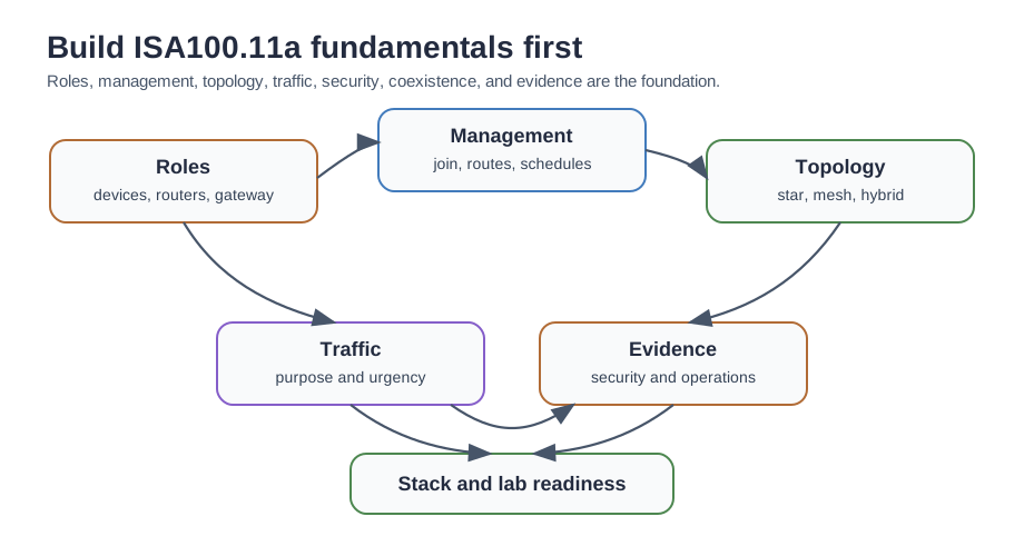
Start with roles Know which devices sense, route, bridge, manage, secure, and integrate before comparing protocol features.
Then check topology Match star, mesh, or hybrid behavior to placement, power source, redundancy, maintenance access, and failure response.
Then classify traffic Separate control, supervision, alerting, diagnostics, maintenance, and logging so the access method fits the consequence of delay or loss.
Then record evidence Capture commissioning, security, coexistence, diagnostics, replacement, and retest assumptions before release.
24.6 ISA100.11a Is a Flexible Industrial Stack on 802.15.4
ISA100.11a, also published as IEC 62734, is a wireless standard for industrial process automation. It runs on the IEEE 802.15.4 2.4 GHz radio, adds a time-scheduled, channel-hopping data-link layer for reliability, and carries an IPv6/6LoWPAN network layer plus an object-oriented application layer that can tunnel several legacy fieldbus protocols. Flexibility is the theme: one network can carry HART, Modbus, Foundation Fieldbus, and Profibus traffic when the gateway and support model are designed for that mix.
That design makes ISA100.11a the more protocol-agnostic industrial wireless option, but it also adds configuration work. A fundamentals review should ask two questions together: can the radio path close with enough margin, and can the management plane keep path, route, key, and gateway records consistent after devices move or fail? A chapter that says only “ISA100 uses IPv6” misses the industrial part of the problem.
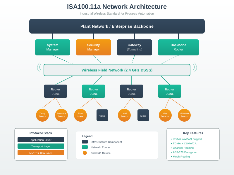
Consider a utility-area monitoring point 100 m from a backbone router in open plant space. A simple 2.4 GHz free-space estimate is FSPL = 40.05 + 20 log10(d_m), so 100 m gives about 80 dB path loss. With a 10 dBm transmitter, 2 dBi antenna at each end, and a receiver that can decode near -95 dBm, the rough received level is 10 + 2 + 2 - 80 = -66 dBm, or about 29 dB above that receiver floor. If the enclosure, pipe rack, and fading budget consume 12 dB + 8 dB, only about 9 dB remains.
That example does not certify a site, but it shows why ISA100.11a fundamentals are not just naming layers. Topology, antenna placement, channel hopping, routing eligibility, and retest triggers all decide whether a scheduled wireless design will keep working after installation. The System Manager, Security Manager, gateway, backbone router, routing devices, and field devices each need an owner, a configuration record, and a failure response. That management effort is the price paid for a flexible stack that can bridge IP-based plant networks and mixed fieldbus payloads without pretending every instrument behaves the same way.
24.7 Core Roles
An ISA100.11a network is not simply “wireless sensors plus a gateway.” It is a managed system with distinct responsibilities.
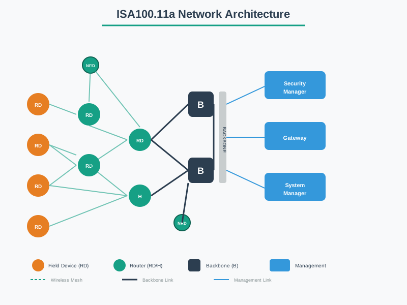
Field device Produces or consumes process values, commands, status, alarms, or diagnostics. It may be battery-powered, line-powered, or connected through an adapter.
Routing device Forwards traffic for other devices. Its placement, power source, and replacement plan affect the health of many paths.
Backbone router Connects the field wireless network to the plant backbone and marks a routing and troubleshooting boundary.
Gateway Exposes data and commands to plant applications, control systems, historians, asset systems, or protocol-tunneling endpoints.
System Manager Controls device roles, join behavior, schedule or route configuration, network policy, and configuration records.
Security Manager Controls device admission, key material, renewal policy, audit events, revocation, and decommissioning behavior.
24.8 Managed Roles Need Ownership Records
An ISA100.11a network is centrally managed by two authorities plus the infrastructure that connects it out. In a design review, these roles should appear in the commissioning packet rather than only in a vendor diagram. Each role changes a different operational question: who admits a new transmitter, who changes a route, who can rotate or revoke keys, who diagnoses gateway translation, and who owns the retest when maintenance replaces a routing device?
| Role | Responsibility |
|---|---|
| System Manager | Administers addressing, communication scheduling, device join policy, network configuration, and performance records. |
| Security Manager | Manages keys, authorizes devices joining the network, records revocation, and preserves audit evidence. |
| Backbone router | Carries traffic over a high-speed backbone between field subnets and the gateway. |
| Gateway | Connects the wireless network to the plant host or control system and owns translation evidence. |
| Field and routing devices | Sense, actuate, or adapt instrumentation; routing devices also relay for neighbors in the mesh. |
The data-link layer uses TDMA with configurable slot timing and channel hopping so transmissions are scheduled and spread across channels to reduce interference exposure. Because scheduling is centralized in the System Manager, the network is more deterministic than a purely contention-based design: a slot can be reserved for a device instead of leaving the message to compete randomly.
Determinism still has to be budgeted. If a site’s configured slot is 10 ms and 48 pressure transmitters each need one normal report plus one reserved retry opportunity during a 30 s reporting cycle, that is 48 x 2 x 10 ms = 960 ms of raw transmit opportunity before acknowledgements, management traffic, route maintenance, alerts, and guard time are considered. A 30 s trend loop can tolerate that; a hard trip loop should not be hidden inside the same assumption.
This is why the practitioner record should classify traffic before approving the topology. A battery transmitter that reports tank level every minute can be a leaf device with a conservative retry policy. A line-powered device placed high on a pipe rack may be allowed to route for neighbors, but then its maintenance window affects several paths, not only its own measurement. A gateway that tunnels a legacy protocol may satisfy the control-system interface, but support must know whether a bad value came from the field device, the wireless hop, the tunnel, or the plant application.
24.9 Management Plane
The management plane is where many industrial wireless designs either become reviewable or become operationally fragile.
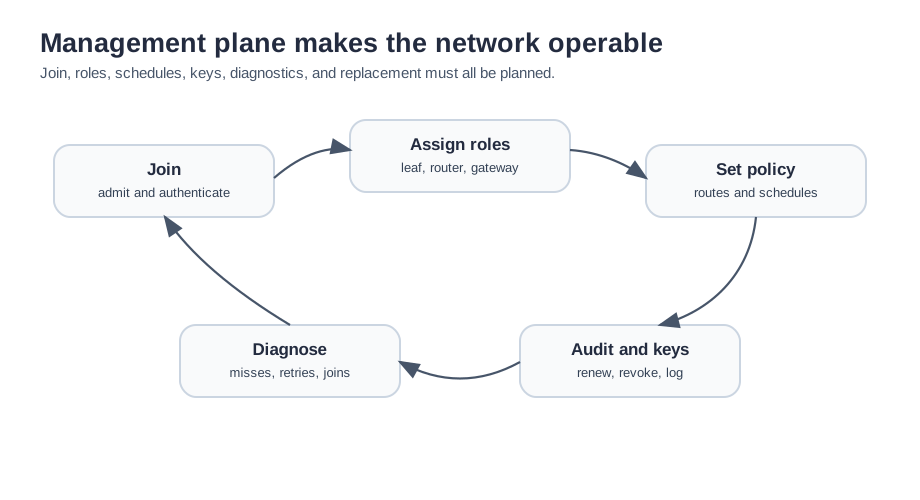
Joining Who approves a device, what credential is used, how failed joins are investigated, and how unauthorized attempts are logged.
Role assignment Which devices are allowed to route, which are leaf devices, and how that choice changes when devices are replaced.
Schedule and route policy Which flows need managed resources, how routes are maintained, and which changes require review.
Security lifecycle How keys are issued, renewed, revoked, backed up, and audited without creating undocumented manual work.
Diagnostics What evidence is available for missed updates, retries, route changes, join attempts, key failures, and gateway translation issues.
Replacement How a failed device is retired, replaced, recommissioned, and tested without accidentally changing the network behavior.
24.10 Topology Choices
ISA100.11a can be described as flexible, but flexibility must be turned into a documented topology choice.
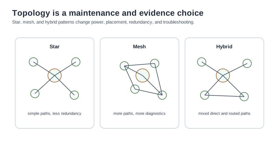
Star pattern Useful when devices can reach a gateway or backbone router directly and the team wants simpler routing behavior. It has less path redundancy.
Mesh pattern Useful when routing through neighbors improves coverage or resilience. It increases dependence on router placement, power, and route diagnostics.
Hybrid pattern Useful when some devices can connect directly while others need routed paths. It requires clear records for which devices are allowed to forward.
Review trigger Recheck topology when equipment moves, enclosures change, routers are replaced, interference changes, or maintenance access changes.
24.11 Traffic and Access
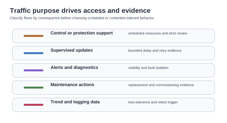
The access method should follow the purpose of each flow. Do not default all traffic to one mode just because the standard permits it.
Traffic review record
For each flow, record: - Purpose: control, supervision, alert, diagnostic, maintenance, or logging. - Owner: controls, operations, maintenance, reliability, IT/OT network, or vendor support. - Consequence: what happens if an update is delayed, lost, duplicated, stale, or out of order. - Access need: scheduled, contention-tolerant, or intentionally separated from normal traffic. - Evidence: site test, missed-update behavior, retry behavior, alarm behavior, route diagnostics, and retest trigger.ISA100.11a usage classes make that traffic discussion concrete. Use the class number as a consequence label, not as a substitute for site evidence.
| Category | Class | Application | Review meaning |
|---|---|---|---|
| Safety | 0 | Emergency action | Always critical; evidence must prove the wireless path is appropriate for the safety claim or explicitly keep the action outside the wireless loop. |
| Control | 1 | Closed-loop regulatory control | Often critical; schedule, retry, stale-value handling, and fallback ownership must be visible. |
| Control | 2 | Closed-loop supervisory control | Usually non-critical, but still needs delay and loss limits tied to the process consequence. |
| Control | 3 | Open-loop control | Human-in-the-loop behavior must show command identity, operator feedback, and timeout handling. |
| Monitoring | 4 | Alerting | Short-term operational consequences require alarm latency, missed-alert behavior, and escalation evidence. |
| Monitoring | 5 | Logging or downloading | No immediate operational consequence, but the record still needs completeness, backfill, and diagnostic ownership. |
24.12 Stack Fit
ISA100.11a fundamentals include the major stack choices, but the detailed comparison belongs in the next chapter.
IEEE 802.15.4 radio Review channel plan, site survey, enclosure effects, antenna position, neighboring radios, and allowed installation locations.
6LoWPAN and IPv6 Review addressing, compression assumptions, fragmentation risk, diagnostics, and border behavior.
Hybrid MAC behavior Review what gets scheduled, what can contend, and how the system reports retries, missed opportunities, and route changes.
Application and tunneling Review native objects, legacy payloads, gateway translation, support ownership, and how teams diagnose tunneled traffic.
24.13 IPv6 and Protocol Tunneling Still Need Budgets
What most distinguishes ISA100.11a from some industrial wireless peers is that it is built on 6LoWPAN and IPv6. Field devices can be addressed in an IPv6 scheme, which makes routing over the backbone and integration with IT infrastructure natural instead of bolted on. On top of that IPv6 transport sits an object-oriented application layer that does not assume a single instrument protocol.
That is what enables protocol tunneling: legacy application protocols such as HART, Modbus, Foundation Fieldbus, and Profibus can be carried as payloads over the ISA100.11a network, so a plant can bring existing instrumentation onto one wireless backbone without standardizing on a single fieldbus. The trade is complexity. Configurable slots, hopping modes, IPv6 addressing, and an object model are more to engineer than a fixed single-profile network, but the payoff is a general-purpose industrial wireless layer rather than a single-protocol one.
The engineering catch is that IP-addressable does not mean Ethernet-sized. IEEE 802.15.4 frames are small, so 6LoWPAN compression and fragmentation matter. Suppose a compact sensor update fits in one wireless frame and each frame attempt succeeds with probability 0.98 in a tested path. One frame succeeds before retry about 98% of the time. If a tunneled request expands into two fragments over a two-hop routed path, the message now depends on roughly four successful frame transmissions, so the no-retry success estimate is 0.98^4 = 0.922. That does not make tunneling wrong; it tells the reviewer to reserve retries, monitor fragment-related failures, and avoid treating every legacy payload like a tiny process-value update.
The same logic applies at the gateway boundary. A host system may see a familiar HART or Modbus object while the wireless network underneath is scheduling slots, compressing headers, routing through one or more devices, changing channels, and applying security policy. Troubleshooting therefore needs layered evidence: device join logs, key state, route history, retry counters, fragment or tunnel diagnostics, gateway translation records, and the application timestamp seen by the plant system.
Under the hood, ISA100.11a is strongest when its flexibility is used deliberately. Keep small periodic measurements, alerts, diagnostics, and tunneled maintenance traffic in separate review buckets. Give high-consequence flows scheduled resources and measured retry behavior. Leave contention-tolerant diagnostics room to operate without starving process traffic. Record when a routed path, key policy, firmware update, enclosure change, or neighboring radio change requires a retest.
24.14 Check IPv6 and Tunneling Evidence
24.15 ISA100.11a Review Notes
Use ISA100.11a when the review needs industrial wireless behavior plus explicit ownership of the management and security planes. A fit review should preserve these questions:
| Review item | What to check |
|---|---|
| IPv6 and 6LoWPAN fit | Addressing, compression, fragmentation, border behavior, and diagnostics must be testable by the team that will operate the network. |
| Hybrid access | Scheduled control traffic, contention-tolerant diagnostics, alerts, and maintenance flows need separate evidence instead of one generic traffic claim. |
| Protocol tunneling | Legacy payloads can cross the network, but gateway translation, troubleshooting, vendor support, and ownership must be written down. |
| Security ownership | Joining, key management, replacement, revocation, and audit roles should be assigned before field devices are installed. |
| Coexistence | Channel plan, enclosure effects, antenna placement, neighboring radios, and retest triggers need site evidence. |
For brownfield utility monitoring, the release record should show which points are operator-facing, which are maintenance alerts, which are trend-only, and which devices are allowed to route. That record prevents a later maintenance change from quietly turning a monitoring mesh into an unreliable control path.
24.16 Worked Example
A plant wants wireless monitoring in several utility areas where cable runs are difficult. Some points feed operator displays, some support maintenance alerts, and some are only trend data. The site has an existing plant backbone and a separate team that manages industrial network security.
The fundamentals review should produce:
- A role map for field devices, possible routers, backbone router, gateway, System Manager, and Security Manager.
- A topology choice for each area, including which devices can route and which cannot.
- A traffic classification record for operator updates, maintenance alerts, diagnostics, and trend data.
- A join and replacement workflow that the maintenance team can execute without hidden steps.
- A coexistence record for mounting, channel plan, enclosure, and neighboring wireless systems.
- A retest trigger list for layout changes, enclosure changes, firmware changes, key-policy changes, and device replacement.
Only after those records exist should the team move into detailed stack comparison or lab/security calculations.
24.17 Common Pitfalls
- Role ambiguity: the design names devices but not who owns routing, gateway diagnostics, management policy, or security lifecycle.
- Topology by diagram: a mesh diagram looks resilient, but router power, placement, maintenance access, and route evidence are not reviewed.
- Traffic flattening: control, alerting, diagnostics, and logging are treated as one traffic class even though their delay and loss consequences differ.
- IPv6 overconfidence: standard addressing is assumed to make diagnostics easy, while compression, fragmentation, and border behavior remain untested.
- Tunneling blind spot: legacy protocol payloads are carried over the network without support ownership or gateway troubleshooting evidence.
- Weak retirement process: devices can join securely, but lost, replaced, or decommissioned devices are not removed from policy and audit records.
24.18 Knowledge Check
24.19 Check the Fundamentals Review
24.20 Match the ISA100.11a Role
24.21 Order a Fundamentals Review
24.22 Summary
ISA100.11a fundamentals are the practical building blocks that make the rest of the standard reviewable. Before comparing stacks or running lab exercises, the team should know who owns the roles, how devices join, which devices route, how topology is maintained, how traffic is classified, how security is managed, how coexistence is tested, and how replacement or decommissioning is handled.
24.23 Key Takeaway
ISA100.11a is best reviewed as a managed industrial wireless system where scheduling, routing, security, and gateway integration must fit the plant workflow.
24.24 See Also
- ISA100.11a Overview: fit decision and release evidence.
- ISA100.11a Protocol Stack: layered stack and WirelessHART comparison.
- ISA100.11a Labs and Security: security keys, tunneling, compression, and practice checks.
- WirelessHART Fundamentals: competing industrial wireless fundamentals.
- 6LoWPAN Fundamentals: IPv6 adaptation for constrained wireless links.
24.25 What’s Next
Continue with ISA100.11a Protocol Stack to compare the layered architecture and WirelessHART trade-offs, then use ISA100.11a Labs and Security to verify key management, tunneling, compression, and evidence records.