14 NFC Modes and Protocols
14.1 Start With the Story
The same phone can read a tag, emulate a card, or exchange data with another device, but those modes have different responsibilities. Confusing the mode usually means confusing who starts, who answers, and what evidence the system can trust.
Use this chapter to slow the tap into roles and protocols. Separate reader/writer, card emulation, peer-to-peer, handover, tag technology, and NDEF so each design decision has the right boundary.
14.3 Learning Objectives
By the end of this chapter, you will be able to:
- Compare reader/writer, card emulation, peer-to-peer, and handover boundaries without mixing their responsibilities.
- Separate RF interface, tag technology, NDEF payload, and application-policy layers.
- Describe polling, anti-collision, selection, and activation at the level needed for design review.
- Choose tag and NDEF patterns from application needs instead of assuming all NFC tags are interchangeable.
- Define release evidence for NFC flows, including device coverage, failure handling, fallback, and trust-boundary checks.
14.4 Quick Check: NFC Mode
14.5 Prerequisites
Before diving into this chapter, you should have completed:
- NFC Fundamentals: NFC range, tap intent, and the difference between active and passive participants.
- RFID Fundamentals: HF RFID concepts, tag selection, and reader-controlled timing.
14.6 NFC as Specialized HF RFID
NFC sits inside the HF RFID family, but it adds operating modes and application conventions that ordinary RFID systems do not always provide. A useful review starts by separating the layers before arguing about tag type or user experience.
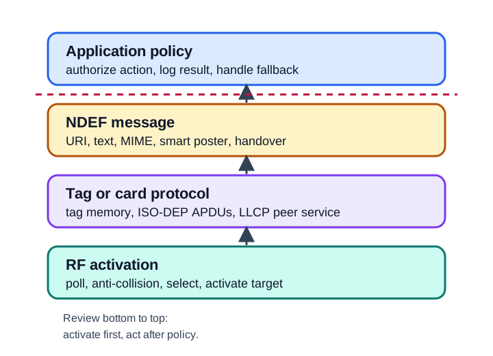
An NFC tap can look simple to the user while several different layers are involved:
- RF and activation decide which nearby target is selected and which low-level protocol is active.
- Tag technology or card protocol decides whether the reader sees tag memory, ISO-DEP APDUs, or a peer link.
- NDEF provides a portable envelope for small records, but it does not prove that the payload is safe or authorized.
- Application policy maps the tap to an IoT action such as pairing, opening a maintenance record, selecting a device profile, or logging an inspection.
14.7 Operating Modes
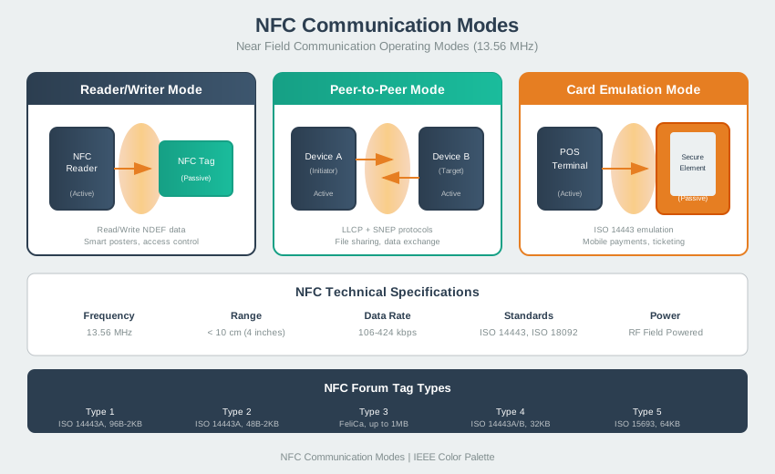
NFC designs should name the mode first, then state who powers the field, who initiates commands, and where policy is enforced.
14.7.1 One Radio, Three Roles
All NFC runs at 13.56 MHz over a few centimetres, but a single NFC chip can take different roles on different taps. A phone may read a poster tag in reader/writer mode, present a credential to a cabinet reader in card emulation mode, and exchange a setup token with another powered device through peer-to-peer or handover. The role switch changes who owns timing, who owns the RF field, and which software boundary must approve the result.
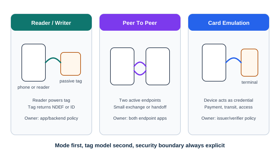
Use an IoT commissioning review as the concrete test. If a phone taps a gateway label to open https://ops.example/setup/GW-142, the phone is in reader/writer mode and the passive label only supplies a small record. The app must still validate the URI, bind it to an authenticated technician session, and ask policy whether this gateway can be configured.
If the same phone is presented to a cabinet reader as a service credential, it is in card emulation mode. The reader powers the field, sends commands, and the phone answers only if the credential application allows that reader application. If two powered devices exchange a setup token, peer-to-peer or handover may apply, but the follow-on Bluetooth, Wi-Fi, Thread, or backend session carries the durable connection.
A useful mode decision names four things before release: the physical role, the payload type, the policy owner, and the fallback. For reader/writer, fallback might be a printed asset ID. For card emulation, fallback might be a manual credential check or denied-entry message. For handover, fallback might be a setup code when the follow-on carrier fails.

Phoebe’s Why
The chapter’s own line – the target replies by load modulation, not by generating its own field – is the physics tell that NFC does not work like a normal radio link. At 13.56 MHz, the free-space wavelength is tens of metres, vastly larger than a coil a few centimetres across, so a tag “a few centimetres” from the reader sits deep inside the reactive near field, coupled magnetically like a transformer, not illuminated by a travelling wave. That is also why NFC’s bit rates are not chosen from a channel-capacity calculation the way a Wi-Fi or cellular rate would be. They are binary fractions of the 13.56 MHz field clock itself, because both ends only ever need to divide down the same field they already share.
The Derivation
Free-space wavelength and the reactive near-field boundary:
\[\lambda = \frac{c}{f}, \qquad r_{nf} \approx \frac{\lambda}{2\pi}\]
Bit rate as an integer division of the carrier clock \(f_c\):
\[R_b = \frac{f_c}{k}, \quad k \in \{32, 64, 128, \dots\}\]
Shannon’s capacity bound, for comparison against what is actually used:
\[C = B\log_2(1+\mathrm{SNR})\]
Worked Numbers: This Chapter’s Own Rates
At \(f_c = 13.56\) MHz: \(\lambda = 3.00\times10^{8}/13.56\times10^{6} = 22.1\) m, so \(r_{nf} \approx 22.1/2\pi = 3.52\) m – the “few centimetres” this chapter quotes is more than 100x closer than that boundary, confirming deep near-field operation.
- NFC-A’s 106 kbps: \(f_c/128 = 13{,}560{,}000/128 = 105{,}938\) bps \(= 105.9\) kbps, which rounds to exactly 106 kbps (3 s.f.) – this chapter’s own quoted rate
- NFC-F’s 212/424 kbps: \(f_c/64 = 211{,}875\) bps \(= 211.9\) kbps \(\to\) 212 kbps; \(f_c/32 = 423{,}750\) bps \(= 423.8\) kbps \(\to\) 424 kbps – both match this chapter’s numbers exactly
- Shannon check: even a modest 1 MHz sideband bandwidth at a generous 30 dB near-field SNR (ratio 1000) allows \(C = 10^6\log_2(1001) = 9.97\) Mbps – about 94x the 106 kbps actually used, so NFC is deliberately run far under its available channel capacity in exchange for the robustness of simple ASK/OOK envelope detection on an unpowered tag
- Unlike a hopping or DSSS radio, NFC does not use spread-spectrum, so no processing-gain figure applies here – the near-field link margin comes from proximity and coupling, not from spreading and despreading a signal against interference
The bit-rate table in this chapter is really a clock-division table wearing kbps units: every rate is one field cycle count away from 13.56 MHz, chosen for a simple divider circuit and reliable envelope detection, not for squeezing the channel toward its Shannon ceiling.
14.7.2 Reader/Writer Mode
Reader/writer mode is the default pattern for smart posters, asset tags, commissioning labels, maintenance tags, and many IoT field workflows. The reader creates the RF field, polls for targets, activates one tag, and performs reads or writes. The tag responds only when selected and powered by the reader field.
Use reader/writer mode when the physical object can carry a passive tag and the application can treat the tap as an input signal. The tag can hold a short identifier, a URI, a configuration hint, or a small signed payload. It should not be treated as the authority for high-impact decisions unless the application verifies the data and the deployment threat model supports that choice.
14.7.3 Card Emulation Mode
Card emulation mode lets a device respond to an external reader as if it were a contactless card. The external reader still controls the RF field and command timing. The emulating device decides, through its local policy and credential storage model, whether it can answer the requested application.
Use card emulation when the environment already has readers that expect card behavior, such as access terminals, fare gates, equipment cabinets, or dedicated service tools. The important design question is not only “can the phone emulate a card?” but also “which application owns the credential, which reader applications are accepted, and how are failed or ambiguous taps handled?”
14.7.4 Peer-to-Peer Mode
Peer-to-peer mode uses NFCIP-1 so two active devices can exchange data over an NFC link. LLCP provides a link layer for peer services, and SNEP is one way to exchange NDEF messages over that link.
Do not assume general-purpose phone-to-phone P2P is available in a deployed device. Many systems instead use NFC for a small handover message and move the longer session to Bluetooth, Wi-Fi, Thread commissioning, or an application backend. Treat P2P as a specific capability to verify, not as something every NFC device will expose to applications.
14.7.5 Handover Boundary
Handover is a boundary pattern, not a promise that NFC will carry the whole session. NFC carries enough information to identify the peer, select a carrier, or pass a setup token. The other bearer owns discovery completion, encryption, reconnect behavior, and bulk data exchange.
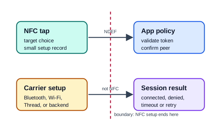
For IoT products, this distinction matters during review:
NFC owns Tap intent, close-range target choice, small setup records, and visible fallback when the tap cannot be parsed.
The carrier owns Pairing completion, session protection, reconnect behavior, throughput, range, and long-running data exchange.
The application owns Authorization, device binding, user confirmation, telemetry, retry rules, and rollback when setup fails.
14.8 Polling, Anti-Collision, and Activation
Before an NDEF record, APDU, or peer message can be exchanged, the reader must find and activate a target. Keep this level of detail in design reviews; diving into every modulation bit is usually unnecessary unless you are building reader firmware.
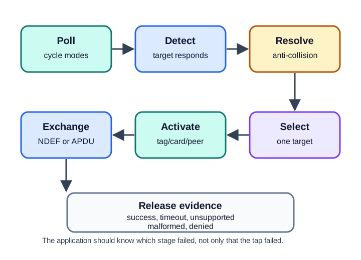
The activation sequence is reader-driven:
- Poll: The reader cycles through supported technologies such as NFC-A, NFC-B, NFC-F, or NFC-V.
- Detect response: A compatible target answers with enough information to continue selection.
- Resolve collisions: If more than one target responds, the reader selects one target at a time.
- Activate protocol: The reader moves into the protocol needed for tag memory, ISO-DEP, or peer exchange.
- Exchange data: Only after activation does the application see NDEF records, APDU responses, or peer payloads.
- Release or retry: The system records success, timeout, unsupported tag, malformed payload, or user-cancel evidence.
- Assuming the closest tag is always the selected tag when multiple targets are inside the field.
- Writing application logic that cannot distinguish “no tag,” “unsupported tag,” “activation failed,” and “payload rejected.”
- Treating a UID or serial-like value as a durable identity without a clone-resistance design and an application-side validation step.
14.9 Initiator, Target, and Passive Communication
Every NFC exchange has an initiator that starts and drives the exchange and a target that responds. In passive communication mode, only the initiator generates the 13.56 MHz field; the target replies by load modulation, varying how much energy it draws from the initiator field. This is the same operating idea that lets an unpowered HF RFID tag answer a reader.
This distinction explains several field failures. A phone can read an unpowered sticker because the phone is the initiator generating the field and the passive tag load-modulates a reply. At a cabinet reader or payment terminal, the fixed reader creates the field and sends commands; the phone acts as the card-emulation target and answers only through an allowed card application. Having a battery does not mean the phone owns the field.
Diagnose NFC failures from the bottom upward:
- No target reported: inspect field coupling, antenna orientation, tag technology support, shielding, mounting surface, and polling configuration.
- Target reported but no NDEF or APDU response: inspect activation, tag type mapping, memory access, ISO-DEP application selection, and record format.
- Payload parsed but action denied: inspect application policy, technician session, object state, authorization, and fallback.
- Handover tap succeeds but setup fails later: inspect peer identity, carrier pairing, session protection, timeout behavior, and rollback.
For card emulation, release evidence should record which application was selected, what happens when the reader asks for an unsupported application, whether user presence is required, and what audit event is emitted for declined or ambiguous taps. A successful “phone seen by reader” test can still hide a credential-policy failure.
14.10 Quick Check: NFC Role
14.11 Tag Types, Technologies, and NDEF
Tag type, RF technology, and NDEF record type are different decisions. They often get collapsed into one phrase, which leads to weak reviews.
Tag technology The low-level family exposed during polling and activation, such as NFC-A, NFC-B, NFC-F, or NFC-V.
NFC Forum tag type The mapping that defines how an NDEF message is stored or accessed on a supported tag.
NDEF record type The application envelope inside the message, such as URI, text, MIME, smart poster, or handover.
Application meaning The product-specific decision made after parsing and validating the payload.
14.11.1 Technology Matrix and Compatibility Evidence
Beneath the modes are RF technologies inherited from HF RFID smart cards. A tap works only when both sides share a supported technology.
| Technology | Based on | Notes |
|---|---|---|
| NFC-A | ISO/IEC 14443 Type A | Common MIFARE and NTAG family; 106 kbps base rate with modified Miller/OOK signaling. |
| NFC-B | ISO/IEC 14443 Type B | Used by many ID and banking-card systems; NRZ/BPSK signaling. |
| NFC-F | JIS X 6319-4, FeliCa | 212/424 kbps; common in Japanese transit and payment deployments. |
| NFC-V | ISO/IEC 15693 | Vicinity-card family; longer practical coupling distance at lower data rate. |
Turn this matrix into release evidence. A field-service app might support low-cost Type 2 labels for equipment lookup, a phone wallet credential for cabinet access, and an NFC handover tag for a Bluetooth sensor. Those are not one test. The label path needs reader/writer tests with the actual tag family, record size, lock state, and mounting surface. The cabinet path needs card-emulation tests against the installed readers and accepted application identifiers. The sensor setup path needs a handover test that proves the NFC record leads to the intended Bluetooth device, not merely that the tag can be read.
Write each result as a small compatibility record: mode=reader/writer, technology=NFC-A, tag_type=Type 2, payload=URI, max_length_checked=true, write_locked=true, fallback=manual asset search. For card emulation, record the reader model or class, selected application, declined-reader behavior, and audit event. For handover, record the carrier chosen, device identity check, timeout behavior, and rollback if the follow-on link fails.
14.11.2 Reader/Writer Tag Choices
Choose tags from the evidence your workflow needs:
- Simple public pointer: A URI or short text record can use a small widely supported tag. Locking after write may be appropriate when the content should not change in the field.
- Field-updated asset state: Prefer a tag and workflow that can verify write success, preserve a previous known-good value, and recover from interrupted writes.
- Structured device commissioning: Store a compact identifier or setup token, then let the application fetch policy from a trusted service or local controller.
- Access or entitlement decision: Do not rely on tag memory alone. Use an explicit credential model, challenge-response design, or backend check as required by the system.
14.11.3 NDEF Message Structure
NDEF is a message format. It is not encryption, not anti-collision, and not proof that the tap should be trusted. A message contains one or more records. Each record identifies its type and carries a payload.
Common record patterns include:
URI record
  Purpose: open or route to a resource
  Review point: validate scheme, host, and expected path

Text record
  Purpose: carry a short human-readable value
  Review point: handle language, length, and unexpected characters

MIME record
  Purpose: carry application-specific structured data
  Review point: parse with a strict schema and reject unknown fields

Handover record
  Purpose: carry setup data for another bearer
Review point: confirm the follow-on connection before changing statePut the smallest useful claim on the tag. The tag can identify an object or propose an action; the application should verify whether that action is allowed in the deployment context.
14.12 Trust Boundaries
The tap is intentional, but the data is still external input. Treat reader/writer, card emulation, and handover flows as separate trust-boundary reviews.
Reader/writer Validate record type, length, encoding, allowed URI schemes, tag write state, and expected object binding before changing IoT state.
Card emulation Limit which reader applications are answered, define user presence rules where applicable, and log declined or ambiguous reader requests.
Peer-to-peer Verify both devices expose the required P2P capability and decide whether peer data is informational, binding, or command-authorized.
Handover Bind the NFC setup token to the follow-on carrier session. A successful tap is not enough evidence that the later connection is the intended one.
14.13 Release Evidence
NFC failures often appear as “the tap did not work.” Good release evidence makes those failures diagnosable before field rollout.
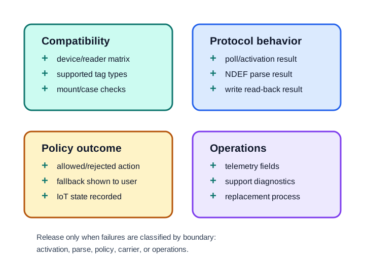
Capture evidence in four areas:
Compatibility Target device matrix, supported tag technologies, reader firmware version, phone operating system range, and case or mounting conditions.
Protocol behavior Polling result, activation success or failure, selected technology, NDEF parse result, write verification, and retry outcome.
Policy outcome Allowed action, rejected action, user confirmation, fallback path, and whether the IoT state changed.
Operations Telemetry fields, support diagnostics, tag replacement process, lost or damaged tag handling, and regression tests for known failures.
14.14 Check Your Understanding
14.15 Match Modes to Responsibilities
14.16 Order the NFC Reader/Writer Flow
Common Pitfalls
Some devices expose reader/writer mode but not general-purpose peer-to-peer services. Some readers only activate specific tag technologies. Verify the mode and technology matrix for the deployment, then document fallback behavior.
An NDEF URI, text record, or MIME payload can be well formed and still be wrong for the target device, user, location, or workflow. Parse first, validate second, act third.
For writable tags, a successful write command is not enough release evidence. Read the tag back, parse the resulting NDEF message, and record what the application will do if the write is interrupted.
If an NFC-assisted setup fails after the tap, separate NFC parse failures from carrier connection failures and application authorization failures. The support path needs to know which boundary failed.
14.17 Design Review Checklist
Use this short checklist before approving an NFC mode decision:
- Mode: Name reader/writer, card emulation, peer-to-peer, or handover. Identify the field generator and command initiator.
- Target technology: List supported tag technologies or card protocols, plus unsupported cases that users may encounter.
- Payload: Define the NDEF records, schemas, maximum accepted length, and rejection behavior.
- Trust boundary: State which component validates the tap and which component is allowed to change IoT state.
- Fallback: Provide a visible path for no tag, unsupported tag, malformed payload, denied action, and follow-on carrier failure.
- Evidence: Attach device coverage, activation logs, parse results, write verification, telemetry fields, and field-test notes.
14.18 Summary
This chapter covered NFC modes and protocols as a layered design problem:
- Reader/writer mode is for passive tags and reader-driven tag memory access.
- Card emulation mode is for devices that answer external readers as contactless card applications.
- Peer-to-peer and handover must be treated as explicit capabilities, with NFC usually carrying only small setup data in modern IoT workflows.
- NDEF is a portable message format, not a trust decision.
- Activation evidence explains whether the system failed to find a target, activate a protocol, parse a payload, or authorize an action.
- Release evidence should cover compatibility, protocol behavior, policy outcome, fallback, telemetry, and operations.
14.19 Key Takeaway
NFC mode selection should match the interaction: reader-writer, peer-to-peer, and card-emulation patterns create different security, data, and user-flow obligations.
14.20 Concept Relationships
Builds On:
- RFID Fundamentals - HF RFID, tag selection, reader timing, and standards context.
- NFC Fundamentals - NFC range, tap intent, and basic active/passive behavior.
Enables:
- NFC Tags and NDEF - Tag family, capacity, record structure, and write-state decisions build on mode choice.
- NFC Communication and IoT Integration - Tap payloads need application policy, controller behavior, and follow-on carrier evidence.
- NFC Security and Comparisons - Threat models and controls depend on the operating mode and trust boundary.
Related Concepts:
- Bluetooth, Wi-Fi, and Thread commissioning often use NFC as a setup input rather than as the long-running connection.
- NDEF records should be schema-checked before they drive IoT actions.
- Tag type choice should be documented with compatibility and release evidence, not only with memory size.
14.21 See Also
Standards and Specifications:
- NFC Forum Specifications - NDEF, tag operation, LLCP, and handover specifications.
- ISO/IEC 14443 - Proximity card communication used by many NFC systems.
- ISO/IEC 18092 - NFC Interface and Protocol specification.
Practice:
- Read a known NFC tag with a phone reader app and identify the record type, payload length, and tag technology.
- Write a test tag with a short URI record, read it back, and document the parse result and fallback if the record is malformed.
- For a handover design, write down exactly what NFC carries and what the follow-on bearer must prove before the application acts.