31 Lab: Z-Wave Network Simulation
z-wave simulation, source routing, mesh topology, failure injection, z-wave validation, smart home testing
31.1 Start With the Story
A Z-Wave simulation is not RF proof, but it is a useful way to test reasoning before buying or moving devices. It can expose topology assumptions, repeater dependency, route repair ideas, and failure scenarios in a controlled space.
Use this lab to separate model evidence from field evidence. Run the scenario, record what the simulation teaches, and write down exactly which behavior must still be validated with real hardware.
31.2 In 60 Seconds
A Z-Wave simulator is useful when it makes assumptions visible. It can test whether a topology graph has enough always-listening repeaters, whether a route exceeds the configured classic-mesh limit, how a controller should react when a route fails, and whether a scenario produces the evidence needed for a design review. It cannot prove RF range, antenna performance, certification status, regional compliance, battery life, or installed reliability. Those claims require real hardware, certified products, controlled measurements, and field validation.
This chapter shows how to design simulation scenarios, inject failures, interpret route evidence, and hand the results to hardware validation without overstating what software-only tests can prove.
31.3 Learning Objectives
By the end of this chapter, you should be able to:
- Define what a Z-Wave software simulation can and cannot validate.
- Build scenario records that separate topology assumptions, device roles, route constraints, events, and assertions.
- Exercise classic mesh routes, sleeping endpoints, and Z-Wave Long Range star links without treating the model as RF proof.
- Inject route, node, inclusion, security, and command-class failures in a controlled way.
- Convert simulation output into a hardware-validation checklist for controller, device, route-health, and installation tests.
- Explain why simulation evidence supports design review but does not replace certification or installed RF validation.
31.4 Quick Check: Z-Wave Simulation
31.5 Core Ideas
- Simulation boundary: the line between modeled behavior and evidence that must come from real devices.
- Scenario record: a repeatable description of topology, device roles, assumptions, events, and pass/fail assertions.
- Topology graph: a software model of nodes and allowed links, not a measured RF map.
- Classic route constraint: the repeater and route rules enforced by the model for classic Z-Wave source-routing exercises.
- Sleeping endpoint: a battery device that wakes for events or maintenance and should not be modeled as an always-available repeater.
- Failure injection: a deliberate simulated fault such as a missing acknowledgement, dead repeater, stale route, failed inclusion, or incomplete interview.
- Evidence handoff: the record that tells a hardware test what the simulator checked, what it assumed, and what still needs real validation.
31.6 The Simulation Boundary
Start every simulation by writing down the boundary. The boundary is not paperwork; it is how you stop a useful model from becoming a misleading claim.
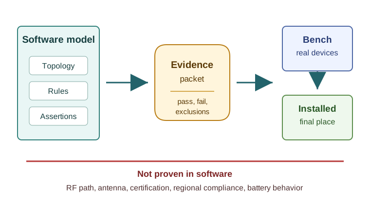
Software simulation can check:
- whether the modeled device roles are coherent;
- whether classic mesh routes stay within the configured repeater limit;
- whether sleeping devices are excluded from repeater paths;
- whether a controller retry or repair policy is triggered after a failed acknowledgement;
- whether a Z-Wave Long Range endpoint is modeled as a direct star link rather than as a mesh repeater;
- whether inclusion, interview, and command flows are complete at the level of states and events;
- whether the scenario produces a clear pass/fail record.
Software simulation cannot check:
- real RF propagation through walls, metal, appliances, water, people, or landscaping;
- antenna orientation, enclosure effects, or installation workmanship;
- regional compliance or device certification;
- controller firmware behavior beyond what the model implements;
- battery life, wake timing, or power behavior under real use;
- interoperability with a specific certified device unless that device is tested;
- user support outcomes after hub migration, firmware updates, or renovations.
Use the simulator to narrow the design question. Use hardware tests to answer the physical one.

Phoebe’s Why
The boundary list above names battery life as something the topology graph cannot check, and that is a statement about chemistry, not software. A cell’s printed mAh is charge, not energy – multiplying by terminal voltage turns it into the joules the radio actually spends. Every real cell also has internal resistance, so the voltage sags under load, worse as the cell ages; a slow chemical leak called self-discharge quietly drains capacity even while the device sleeps; and a design margin has to be reserved so the node shuts down cleanly instead of browning out mid-transmission. None of that shows up as a failed assertion in a route simulator, because a graph search has no concept of joules, volts, or milliamp-hours – only of which nodes are reachable.
The Derivation
Charge and delivered energy, related through terminal voltage:
\[E\,\mathrm{(Wh)} = C\,\mathrm{(Ah)} \times V\]
A cell under load sags by its internal resistance \(R_{int}\):
\[V_{load} = V_{oc} - I\,R_{int}\]
Usable charge after self-discharge over time \(t\) and a design derating margin \(\delta\):
\[C_{usable} = C_0\,(1-k)^{t}\,(1-\delta)\]
Energy spent by one radio transmit-plus-acknowledgement step of current \(I\), voltage \(V\), and duration \(t\):
\[E_{step} = I \times V \times t\]
Worked Numbers: The Cost of a Repair
This chapter fixes no cell or transceiver current, so take standard, catalog-typical figures for a battery contact sensor: a CR2032 cell (\(V=3\) V, \(C_0=220\) mAh), a 30 mA classic Z-Wave transmit current, and this chapter’s own 40 ms transmit-plus-ack step.
- Energy per step: \(E_{step} = 0.030\times3\times0.040 = 3.60\) mJ
- This chapter’s own healthy-scenario counters – 1 normal attempt, 2 retries, 5 explorer-related transmissions – total 8 steps before the route recovers: \(E_{repair} = 8\times3.60 = 28.8\) mJ, exactly \(8.00\times\) the 3.60 mJ a single clean transmission would have cost
- Usable cell energy after a standard 1%/year self-discharge over a 5-year service life and a 20% derating margin: \(C_{usable} = 220\times(0.99)^5\times0.80 = 167\) mAh, so \(E_{usable} = 167\times3 = 502\) mWh
- One repair event spends \(28.8/502{,}000\times100\% = 0.00159\%\) of that budget – trivial once, but a weak topology that triggers a repair roughly once an hour burns \(0.00159\%\times24 = 0.0382\%\) per day, exhausting the entire budget in about 2{,}620 days (7.16 years) from repair traffic alone, before ordinary reporting or sleep current are even counted
That last line is the physical reason the boundary list treats “letting sleeping devices repeat” and “no failed-route case” as design defects rather than style preferences: every explorer flood the simulator logs as a free assertion is a real millijoule charge on a coin cell the model cannot see. It compounds further with a poorly matched antenna – a small coin-cell PCB antenna typically radiates at only about 50% efficiency, so half of every one of those millijoules never leaves the device as RF power at all, which is exactly the kind of range shortfall that forces more retries and more explorer floods in the first place.
A useful model might contain 1 controller, 7 always-listening classic repeaters, 3 FLiRS locks, 14 sleeping sensors, and 1 Long Range endpoint. It can test whether the classic lock route uses only repeaters, whether a route stays inside the configured repeater limit, and whether the LR endpoint remains a direct gateway link. It cannot prove that the garage wall, metal door, antenna orientation, or regional device choice will work in the actual building.
Make every route an assumption with a label. For example, the model can say that Node 21 lock reaches the controller through Node 6 stair switch and Node 12 hall plug. That is design evidence only if the run also records that the Node 12 link is synthetic and must be validated later with the installed plug powered in its final outlet.
Use simulation to reject bad designs early. If the only passing route uses a sleeping contact sensor as a repeater, the model should fail. If moving one plug removes every route to a critical lock, the design needs another fixed repeater or a different topology. If the model passes only by treating an LR endpoint as a classic repeater, the rules are wrong and the pass result should be discarded.
31.7 Scenario Design
A useful scenario is small enough to explain and strict enough to fail. Avoid demonstrations that only show a happy path. A route simulation that never loses a repeater, never sleeps a battery device, and never records assumptions is just an animation.
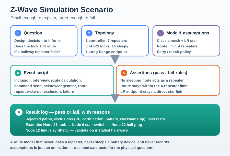
Each scenario record should include:
- Question: the design decision the simulation is meant to inform.
- Topology: controller, classic repeaters, sleeping endpoints, LR endpoints, and allowed links.
- Mode: classic mesh, Z-Wave Long Range star, or a mixed model with both called out.
- Assumptions: route limit, retry policy, wake behavior, failed-node timing, and any simplified RF rule.
- Events: inclusion, interview, route calculation, command send, acknowledgement, route repair, wake-up, exclusion, or failure.
- Assertions: the exact conditions that mark the run as pass or fail.
- Known exclusions: RF measurements, certification, real controller quirks, battery behavior, and installation workmanship.
Good scenario questions are concrete:
- Can the modeled door lock still receive a command if one hallway repeater fails?
- Does the simulated route ever use a sleeping contact sensor as a repeater?
- Does the network record a failed interview before the device is accepted?
- Does an LR endpoint remain a direct star endpoint rather than improving the classic mesh?
- Does the handoff record say which hardware evidence is still missing?
31.8 Route and Topology Exercises
Topology exercises should teach the route decision, not promise a deployment result.
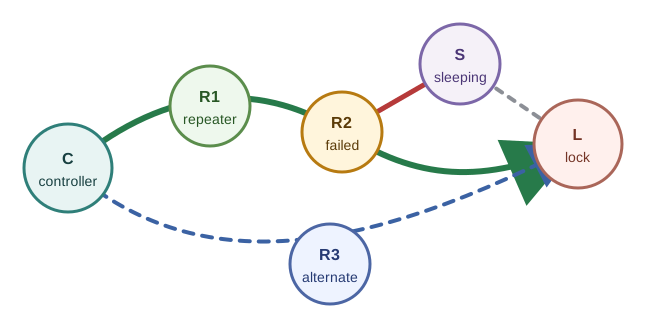
31.8.1 Exercise 1: Classic Route Feasibility
Model a controller, several always-listening repeaters, one sleeping sensor, and one lock. Define the allowed classic-mesh links manually. Then ask the simulator to find a path from the controller to the lock.
The pass condition is not “a route exists.” The pass condition is stricter:
- the route uses only always-listening classic mesh devices as repeaters;
- the route respects the configured classic repeater limit;
- the route does not use a sleeping battery endpoint as a forwarding node;
- the run records which link assumptions were synthetic and require RF validation.
If the path only works because the model allowed an endpoint to repeat while asleep, the model is wrong even if the graph search succeeds.
Run it: Test this controller-to-lock route in the source-routing animation below. Set the Route Request destination to Front lock #62 and run Discover Route to watch the controller build the hop list inside the command frame, checking that only always-listening repeaters carry it. Then compare a Cache hit against a Stale route, and use Clear Cache, to see when the controller trusts a cached path versus rediscovering one – the feasibility evidence this exercise asks you to record.
31.8.2 Exercise 2: Repeater Failure
Start with a passing route. Then remove one modeled repeater or force it to miss acknowledgements.
The simulator should record:
- the original route;
- the failure event;
- the retry or repair trigger;
- the alternate route if one exists;
- the reason for failure if no valid route remains;
- the hardware test that must confirm real route repair behavior.
The lesson is not that Z-Wave always heals instantly. The lesson is that route repair is observable evidence and must be tested with the actual controller and devices before acceptance.
Run it: Start from a working route in the mesh animation below, then break it. Pick a Source node and Destination node, let the route form through the repeaters, then use Fail the selected repeater and watch the Route Evidence show the failure, the repair trigger, and the alternate path – or the reason none remains. Raise the Wall / placement penalty or change the Radio range model to see how a marginal repeater turns a passing route into one that needs real-hardware confirmation, exactly the evidence this drill records.
31.8.3 Exercise 3: Sleeping Endpoint Timing
Model a battery sensor that wakes only during event or maintenance windows. Send an application command or configuration update while it is asleep.
The expected result should be one of these:
- queue the command if the modeled device class and controller policy support that behavior;
- mark the command as waiting for wake-up;
- fail the command if the scenario policy requires immediate delivery.
Do not let the simulator hide wake behavior by treating battery devices as permanently available.
31.8.4 Exercise 4: Classic Mesh and Long Range Side by Side
Model one classic mesh endpoint and one Z-Wave Long Range endpoint. The classic endpoint may use repeaters. The LR endpoint should be modeled as a direct gateway-to-device star link.
The pass condition is that the model keeps the two topology rules separate. An LR endpoint may solve a direct-reach design problem, but it should not be counted as a classic mesh repeater unless the target product and controller documentation explicitly support that role.
31.9 Latency, Associations, and Timing Assumptions
Two models pay off immediately. First, model latency by hop count. Each hop adds transmission time, per-node processing, and acknowledgements, so a four-hop path is meaningfully slower than a direct path. Z-Wave data rates are modest compared with Wi-Fi, so the simulation should make hop count and retry cost visible instead of hiding them behind a single “reachable” result.
| Route | Modelled behavior |
|---|---|
| Direct, 0 hops | Lowest latency; one transmit and acknowledgement. |
| Multi-hop, up to the configured classic route limit | Latency accumulates per hop; every hop adds another chance for retry or repair. |
Keep timing arithmetic honest by making it a model parameter, not a product promise. For a workshop scenario, you might assign 40 ms of modelled time to each transmit-plus-ack step. A direct command then costs one step, a route through two repeaters costs roughly three steps, and a route through four repeaters costs roughly five steps before any retry. Those numbers are not measured Z-Wave latency; they are a visible assumption that lets students compare route shapes.
Now add retries. If the scenario allows 2 retries after a failed acknowledgement, a marginal four-repeater path can consume three attempts before repair starts. The result log should show each attempt, the failing segment, and whether the route finally succeeded, switched to an alternate, or escalated to Explorer Frame discovery. That timeline is more useful than a green “reachable” label because it explains why a command feels slow after a device has moved.
Second, model associations. The Association command class lets one device directly control another, such as a wall switch bound to a lamp module, without a hub round trip for that action. Modelling associations shows why an associated pair can react faster and continue working when the controller is busy or offline.
Associations need the same discipline as route timing. A switch-to-lamp association can be modelled as direct device control only when the scenario states the source device, target device, group, and command being sent. If the lamp also participates in hub-driven scenes, the test should include two assertions: direct association still toggles the lamp when the hub is busy, and the hub scene still records or recovers state according to the controller behavior being modelled.
Hand the timing model to hardware validation. The bench test does not need to reproduce the placeholder milliseconds. It needs to verify that direct, two-repeater, and repaired routes are distinguishable in controller diagnostics or command observations, and that association behavior matches the selected devices rather than the simplified model.
31.10 Failure Injection
Failure injection is the most valuable part of a simulation chapter because it turns a drawing into evidence. Inject one fault at a time so the result remains explainable.
Useful faults include:
- Dead repeater: remove a mains-powered routing endpoint and verify that affected routes are recalculated or marked failed.
- Stale route: keep an old path after a repeater moves and verify that failed acknowledgements trigger repair evidence.
- Sleeping endpoint: send configuration while a battery device is asleep and verify wake-up handling.
- Failed inclusion: simulate a device that starts inclusion but never completes interview or security setup.
- Wrong role: mark a battery sensor as a repeater and confirm the scenario rejects that topology.
- Command-class mismatch: include a device whose advertised behavior does not satisfy the automation requirement.
- Regional mismatch placeholder: mark a device as incompatible by region and verify that the model blocks inclusion, while clearly noting that the simulator did not test radio hardware.
- Controller migration: remove the controller identity or route database and verify which evidence must be restored from backup or rebuilt.
For each fault, record three things:
- What the simulator changed.
- What assertion failed or passed.
- What real-device test remains before deployment.
31.11 Explorer Frame Flood and Retries
The most instructive thing to simulate is what happens when a route breaks. A Z-Wave transmission is acknowledged with retries, so first model the retry: a lost frame is retransmitted according to the scenario policy, each attempt adds latency, and then the node gives up on that route. When known routes are exhausted, an Explorer Frame can spread outward through the network to discover a new path.
That flood is controlled, but it is still much more expensive than a normal routed message. Neighbours rebroadcast under a hop budget, duplicate suppression keeps repeated frames from expanding forever, and the destination reply lets the network cache a recovered path. A simulation reveals the cost: route repair briefly generates more traffic than a normal command, which is why explorer behavior is a last resort rather than the default.
Use an event log rather than a single final state. A route-repair scenario for Node 21 can start with cached path controller -> 6 -> 12 -> 21. At event 1, remove Node 12 or mark its acknowledgement as failed. At event 2, retry the same route according to policy. At event 3, try an alternate stored path such as controller -> 8 -> 14 -> 21. At event 4, if stored paths fail, launch the explorer-frame search.
The flood model should track duplicate suppression and hop budget. If Node 6 and Node 8 both hear the explorer, each may rebroadcast according to the ruleset. If Node 14 receives duplicates, it should forward only according to the model’s suppression rule. If every discovered candidate exceeds the classic repeater limit, the run should fail with “no valid classic route” instead of inventing a longer path.
Record three counters: normal route attempts, repair transmissions, and accepted path length. A healthy scenario might show 1 normal attempt before failure, 2 retries, 5 explorer-related transmissions, and then a recovered two-repeater route. A weak scenario might show many repair transmissions but no valid route because the only apparent bridge was a sleeping endpoint.
31.12 Release Rule
Accept simulation evidence only when the result log names the assumptions, the injected fault, the pass/fail assertion, and the hardware proof still required.
31.13 Quick Check: Explorer Flood
31.14 Evidence Handoff
Simulation evidence is most useful when it is written for the next reviewer. A good handoff says, “Here is what the model checked, here is what it assumed, and here is what hardware must still prove.”
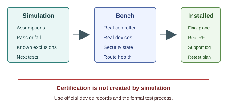
The simulation evidence packet should include:
- scenario name and purpose;
- model version or ruleset;
- topology graph and device-role list;
- event script and injected faults;
- pass/fail assertions;
- failed paths, repair attempts, and excluded routes;
- known exclusions and hardware follow-up items.
Bench validation should then check:
- inclusion and exclusion with the actual controller and target devices;
- reported security class and command-class interview completion;
- controller route or health diagnostics after real commands;
- behavior when a real repeater is powered down and restored;
- sleeping-device wake, report, and configuration behavior;
- logs that show failed acknowledgements, retries, or repair actions where available.
Installed validation should then check:
- final physical placement, not a bench layout;
- regional device compatibility;
- route health after every major device is installed;
- critical device behavior after route repair or network heal;
- support records for controller backup, failed-node removal, device replacement, and future retest triggers.
Certification remains separate. A simulator can help prepare a product or installation review, but it does not certify a Z-Wave device, validate RF compliance, or prove that a mixed installation meets certification requirements.
31.15 Worked Scenario
A design review needs to decide whether a smart lock near an exterior door has enough classic mesh support. The team has not installed hardware yet, so they build a software scenario.
The scenario model includes:
- one controller in the utility room;
- three mains-powered routing endpoints between the controller and the door;
- one smart lock at the edge;
- two battery contact sensors near the door;
- one optional LR sensor elsewhere on the property.
The first run passes because the lock route uses two mains-powered repeaters. The contact sensors are excluded from route paths. The LR sensor is modeled as direct to the gateway and does not improve the classic route.
The failure run powers down the hallway repeater. The simulator finds one alternate route through a different always-listening device, but that route is marked marginal because it depends on a synthetic link. The result is a conditional pass:
- The topology has at least one alternate software path.
- The model did not prove the alternate path exists in the building.
- Hardware validation must test the lock from final placement, power down the hallway repeater, send real lock commands, and record controller diagnostics.
The review decision is to keep the design as a candidate, not to accept the installation. The simulator reduced the risk before hardware arrived; it did not replace the installation test.
31.16 Knowledge Check
31.17 Match the Evidence Types
31.18 Order the Simulation Workflow
31.19 Common Mistakes
Treating the graph as an RF survey. A route edge in software is an assumption until measured or observed with real devices.
Letting sleeping devices repeat. This creates false paths and hides a weak classic mesh.
Mixing classic mesh and LR rules. A Z-Wave Long Range endpoint should not be counted as a classic repeater in a route exercise.
Running only the happy path. A useful simulation includes at least one failed acknowledgement, removed repeater, incomplete interview, or sleeping-device case.
Accepting a device because inclusion was simulated. Real inclusion must verify controller support, device state, security class, command-class interview, and regional compatibility.
Reporting certification from simulation. Simulation can prepare evidence for review, but certification requires the formal process and certified device records.
31.20 Simulation Review Checklist
Before accepting a simulation run as design evidence, check that:
- the scenario has a clear question;
- the model separates controller, classic repeater, sleeping endpoint, and LR endpoint roles;
- route limits and retry behavior are explicit;
- each pass/fail condition is written before the run;
- at least one failure was injected;
- result logs identify assumptions and excluded evidence;
- hardware follow-up is specific enough for another person to execute;
- no RF, battery, range, cost, or certification claim is made from software-only output.
31.21 References
31.22 Summary
Z-Wave simulation is strongest when it is narrow, explicit, and connected to hardware follow-up. It can test route logic, role classification, failure handling, and evidence quality. It cannot validate RF hardware, certification, regional compliance, installed reliability, or battery behavior. Good simulation records make those limits visible and hand the remaining questions to bench and installed validation.
31.23 Key Takeaway
A Z-Wave simulation should test inclusion, routing, device failure, latency, and scene behavior before assumptions reach a real installation.
31.24 Concept Relationships
Builds on:
- Z-Wave Overview and Fundamentals: protocol purpose, regional context, and ecosystem position.
- Z-Wave Architecture and Devices: Home ID, Node ID, controller, repeater, sleeping endpoint, and LR topology roles.
- Network Topologies: graph reasoning, route paths, and topology tradeoffs.
Prepares for:
- Z-Wave Routing and Healing: deeper route repair, failed acknowledgements, and diagnostic evidence.
- Z-Wave Network Planning and Acceptance: converting topology evidence into installation choices.
- Hardware acceptance testing with the selected controller, devices, and installed environment.
Compares with:
- Zigbee Fundamentals and Architecture: distributed mesh behavior and coordinator/router roles.
- Thread Network Architecture: IPv6 mesh behavior and border-router responsibilities.
31.25 Try It Yourself
Create a five-node scenario with one controller, two mains-powered repeaters, one sleeping sensor, and one critical endpoint. Run three paper or software passes:
- Baseline route with all repeaters available.
- One repeater removed.
- Sleeping sensor incorrectly marked as a repeater.
For each pass, write the route result, the assertion outcome, and the hardware evidence still required. The final answer should not be “works” or “fails”; it should be a short evidence packet that another reviewer can use.
31.26 What’s Next?
- Z-Wave Routing and Healing: study route repair behavior in more detail.
- Z-Wave Network Planning and Acceptance: use simulation evidence to plan real device placement and acceptance checks.
- Z-Wave Overview and Fundamentals: revisit protocol context if the simulation assumptions are unclear.