19 Lab: NFC Reader Simulation
19.1 Start With the Story
A simulation cannot prove the RF field, but it can make the NFC logic visible. Polling, anti-collision, NDEF parsing, policy checks, and failure cases become easier to inspect when the lab removes the hardware uncertainty.
Use this chapter as a dry run for reasoning. Treat each simulated trace as evidence about the protocol and policy path, then mark which claims still need hardware before anyone calls the result field-ready.
19.2 Learning Objectives
By the end of this chapter, you should be able to:
- Define what an NFC reader simulation can and cannot prove.
- Model the reader state sequence from polling through tag selection, NDEF parsing, policy validation, and release evidence.
- Decode simple NDEF TLV and URI records well enough to spot length, type, and host-validation failures.
- Simulate multi-tag, malformed-payload, cloned-static-data, and relay-risk scenarios without overclaiming physical accuracy.
- Convert simulation output into a test record that can guide later hardware and field validation.
19.3 Quick Check: NFC Simulation
19.4 Simulation Scope
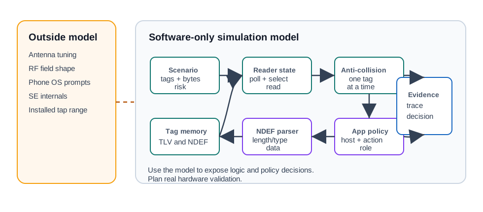
An NFC simulation is useful when it is honest about its boundary. A browser or microcontroller sketch can model bytes, state transitions, and policy checks. It cannot prove the final tap range, detuning, operating-system prompts, secure-element behavior, or user workflow until the target phones, tags, cases, and mounting surfaces are tested.

Phoebe’s Why
A Wi-Fi or BLE reader’s coverage is described by antenna gain in dBi – how tightly a fixed transmit power is focused into one direction – and EIRP is the resulting concentrated power a regulator caps. That whole framework assumes the receiver sits many wavelengths away, out in the antenna’s radiating far field. NFC deliberately works the opposite way: the reader and tag coils are magnetically coupled like two loosely wound transformer windings, not a transmitter and receiver exchanging a travelling wave. There is no beam to aim and no dBi number to look up, because the tag never leaves the region where the field still behaves like a slowly changing induced current rather than a propagating wave. That is the physical reason this chapter’s simulation boundary explicitly excludes “exact antenna field shape” and “installed read range” – those are near-field coil-geometry effects, not protocol logic a software model can reach.
The Derivation
The far-field framework used elsewhere in this book: an antenna redirects fixed power into a solid angle, and EIRP is the regulator-facing result.
\[G(\mathrm{dBi}) = 10\log_{10}\!\left(\frac{4\pi}{\Omega}\right), \qquad \mathrm{EIRP(dBm)} = P_t(\mathrm{dBm}) + G(\mathrm{dBi})\]
The near/far-field boundary is set by wavelength:
\[\lambda = \frac{c}{f}, \qquad r_{near\text{-}field} \approx \frac{\lambda}{2\pi}\]
Inside that boundary, coupling is governed by mutual inductance between two coaxial loops (reader radius \(a\), tag radius \(b\), separation \(d\)), not by radiated gain:
\[M \approx \frac{\mu_0\pi a^2 b^2}{2\left(a^2+d^2\right)^{3/2}}\]
Worked Numbers: 13.56 MHz Read Range
- Near-field boundary: \(\lambda = 3.00\times10^{8}/13.56\times10^{6} = 22.1\) m; \(r_{near\text{-}field} = 22.1/2\pi = 3.52\) m
- Every tap this chapter simulates happens at a few centimetres – deep inside that 3.52 m boundary, so there is no far field to describe with a gain number
- Using standard/typical coil sizes (reader \(a=2.5\) cm, tag \(b=1.5\) cm, single-turn approximation): at \(d=1\) cm, \(M \approx 14.2\) nH; at \(d=4\) cm, \(M \approx 2.65\) nH – a \(14.2/2.65=5.38\times\) drop in coupling for just a \(4\times\) increase in distance
- Induced tag voltage follows Faraday’s law, \(V_{tag}\propto \omega M I_{reader} = 2\pi f\,M\,I_{reader}\), so raising the operating frequency raises the coupled voltage for the same coil geometry – one reason 13.56 MHz was chosen over a lower ISM frequency, not a gain-pattern reason
That steep, geometry-driven falloff is the real physics behind “tap range,” “case effects,” and metal-mounting detuning: none of them are a radiation pattern narrowing, so none of them can be fixed by picking a higher-gain antenna. Orientation and coil-axis alignment set the working envelope here, not a beamwidth number.
19.5 Reader State Model
Start with a small state machine. The simulation should make each transition explicit so a bad tag, ambiguous field, malformed record, or policy denial is visible rather than hidden behind a single “read failed” message.
19.5.1 Minimal Scenario Record
Use a compact scenario record instead of a long copied code listing. The record should describe what the simulated reader sees, not pretend to be real RF data.
19.6 Activation Loop Trace
Simulating an NFC reader means modelling a repeating loop, not a single read. The reader energizes the 13.56 MHz field, polls supported technologies such as NFC-A, NFC-B, NFC-F, and NFC-V, detects a response, resolves one target out of any crowd, activates it, exchanges data, and releases the target before polling again.
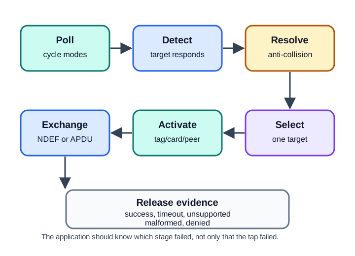
A useful simulator logs transitions instead of returning only “tag read” or “read failed.” For a maintenance tag, the trace might say: field on, Type 2 candidate detected, UID selected, NDEF TLV read, URI decoded, host accepted, app authorization still required. That trace lets a review distinguish a polling miss, collision-resolution issue, payload rejection, policy denial, or release-evidence outcome.
The simulation boundary should be explicit in the same report. A software-only lab can prove that the parser rejects a malformed TLV length, that policy rejects an unknown URI host, and that the application asks the user to isolate one label when two tags are in the field. It cannot prove antenna tuning, installed read range, phone operating-system prompts, secure-element behavior, or the effect of mounting a label on metal.
Use a simple release example. If the target deployment is a gateway tag carrying https://ops.example/A7, the simulation should accept that reference only after checking the NDEF record type, URI scheme, allowed host, payload length, and duplicate-read rule. It should still stop short of service action until an authenticated app session and backend work-order state allow it.
19.7 Activation Sequence Details
Model the activation sequence as distinct states so failure injection can name exactly where the workflow stopped:
- Field on and technology polling: the reader sends each technology’s poll command, such as
REQA/WUPAfor NFC-A orSENSF_REQfor NFC-F, and listens for a technology-specific response. - Anti-collision: if more than one card answers, the reader resolves one UID or target identifier so it talks to exactly one device.
- Select and activate: the reader issues
SELECTor the technology equivalent to put the resolved target into the active state. - Protocol activation: for a Type 4 or ISO-DEP card, the reader runs
RATSto learn card capabilities, then exchanges ISO 7816-4 APDUs such as application selection by AID and command/response pairs. - Release: the card is deactivated and the polling loop resumes.
Run it: Steps 3 and 4 are a command-then-response exchange – watch one play out in the card-emulation workbench below. The terminal starts the conversation, the AID selects an app or secure element route, and each command draws a response until a security policy decides the result. Switch between the Host card emulation app and the Secure element route, then Show a common failure to trigger No matching route – the unknown-host case this lab injects – so you can name which activation state owns the failure.
This is where the lab earns its keep. You can inject a second card at the anti-collision step, drop the field mid-APDU, corrupt a TLV length, or delay a response and then ask which state owns the failure. The point is not to imitate every analog timing detail; it is to make the reader software obligations explicit enough that the review can separate parser, policy, and follow-up hardware risks.
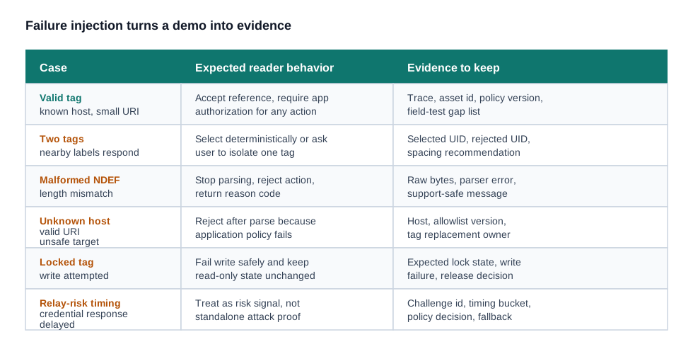
A practical scenario table should include one clean tag and several negative cases. In the clean case, a Type 2 tag advertises an NDEF Message TLV, the parser finds a URI record, and policy accepts the host. In a malformed case, the TLV length claims more bytes than the buffer contains, so the parser must reject before policy sees a partial URI. In a multi-tag case, anti-collision selects one UID, but the application may still reject a maintenance write because two nearby labels create user ambiguity.
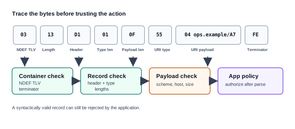
The byte trace can stay small. For example, 03 13 means an NDEF Message TLV with length 0x13, or 19 bytes, before the FE terminator. The record header D1 indicates a short well-known record with message-begin and message-end set. The URI record type 55 is followed by URI identifier code 04, which abbreviates the https:// prefix, and the remaining payload bytes spell the host and path.
19.8 Folded Hands-On Pilot Notes
A useful NFC hands-on pilot separates tap intent, payload design, app policy, and field testing:
| Pilot checkpoint | Evidence to capture |
|---|---|
| Tap intent | What the user expects the tap to select, open, or hand off. |
| NDEF payload | Record type, host, schema version, payload size, and unsupported-record behavior. |
| Application policy | Session requirement, role check, object-state check, fallback path, and audit event. |
| Field test | Final tag surface, phone models, cases, label overlay, tap-zone marking, and damaged-tag behavior. |
| Release record | Owner, app version, tag batch, replacement process, and failure reason codes. |
Use the simulator for parser behavior, duplicate reads, anti-collision paths, malformed records, and policy denials. Then run a physical pilot before release, because software-only traces cannot prove installed read range, phone prompts, metal detuning, or user handling.
19.9 Folded Lab Evidence Record
When the lab uses a real tag, phone, USB reader, or supplied trace, finish with one evidence record that separates observation from authorization:
| Evidence field | What to record |
|---|---|
| Reader path | Phone app, USB reader, embedded reader, or supplied trace. |
| Raw evidence | Saved trace, tag type, UID if exposed, NDEF bytes, record order, and read timestamp. |
| Decode result | Record type, payload length, URI prefix, host, text encoding, schema version, and terminator handling. |
| Validation result | Approved host, allowed record type, object reference exists, malformed length rejected, duplicate tap behavior. |
| Action boundary | Which action may proceed after app policy, and which actions must never follow from read success alone. |
| Retest trigger | Payload format, reader path, policy, tag replacement, mounting material, or installation change. |
This record is intentionally small. It should prove that learners can plan a payload, read it, decode it, reject bad cases, and explain why “tag read” is not the same as “action allowed.”
19.10 NDEF Trace Review
The simulation should teach byte-level reasoning without burying the learner in a thousand-line sketch. The important question is whether the parser and application disagree with the raw bytes.
19.10.1 Parser Checks
19.11 Interactive Scenario Runner
Use the runner to inspect a few common cases. It intentionally models logical reader decisions and application policy only; final hardware behavior still needs field testing.
Reader Trace
Evidence Review
19.12 Failure Injection Matrix
A useful lab does not only show the happy path. It should include failure scenarios that force the reader and application to explain their decision.
19.13 UID Anti-Collision and Cascade Levels
The step that surprises people is anti-collision, because NFC has to single out one card from several sharing the field with no central schedule. For NFC-A, ISO/IEC 14443-3 Type A uses bit-oriented anti-collision over the card UID. Cards reply with UID bits; when two disagree at a bit position, the reader detects the collision, fixes the prefix, and asks again. That binary walk continues until one card is uniquely identified.
Because UIDs can be 4, 7, or 10 bytes, this happens in cascade levels: CL1, CL2, and CL3. Each level resolves part of the UID, and a cascade tag byte signals that more UID bytes follow. Once the full UID is known, SELECT activates that one card. NFC-B uses a different time-slotted anti-collision process, so a simulator should not pretend all technologies resolve collisions the same way.
The simulator should expose the difference between reader capability and application safety. The reader may correctly resolve one Type A card from two candidates, but a maintenance workflow may still reject the action because two nearby labels create user ambiguity. For a read-only lookup, selecting one card may be acceptable. For a write, lock, or credential action, policy may require one visible target in the field before proceeding.
Cascade-level logging also protects the model from treating every UID as an opaque string. A 4-byte UID can be resolved in one cascade level, while longer UIDs require later levels after the cascade tag indicates that more bytes follow. If the model never records those steps, it cannot test partial UID handling, duplicate prefixes, or mistaken selection after a collision.
Finally, keep relay-risk modelling honest. A software scenario can simulate stale challenge identifiers, delayed responses, duplicate credential observations, and policy decisions that deny high-value actions. It cannot prove that a real relay attack was prevented by timing alone. The right output is a trace and a reason code: challenge freshness checked, response outside expected bucket, action denied or escalated, audit row recorded, physical or credential review required.
19.14 Quick Check: Anti-Collision
19.15 Worked Example: Maintenance Tag Review
A facilities team wants tags on gateways and air handlers. A tap should open the correct maintenance record and allow a technician to create a service note. The team wants a simulation before buying production labels.
19.15.1 Simulation Design
19.15.2 Acceptance Evidence
The simulation is ready for field testing only when it produces evidence for both accepted and rejected paths:
- Accepted tag opens the asset record only after the app session is valid.
- Unknown host, malformed NDEF, and oversized payload are rejected with clear reason codes.
- Multi-tag behavior is documented so label spacing can be checked in the physical layout.
- Write tests include read-back validation and expected lock state.
- The report states what the simulation does not prove: tap range, antenna detuning, case effects, and phone operating-system prompts.
19.16 Common Pitfalls
- Using a new-project simulator as evidence. A generic board page does not validate an NFC workflow unless the scenario, parser, policy, and failure cases are explicit.
- Confusing parsed data with trusted data. Valid NDEF syntax only means the bytes decoded. The application still needs host, type, length, schema, and authorization checks.
- Overclaiming relay detection. Timing signals can inform risk, but credential flows need challenge freshness, policy, audit, and fallback decisions.
- Skipping negative tests. A lab that only shows a valid URI does not prepare the deployment for replaced tags, partial writes, nearby labels, or corrupted data.
- Forgetting physical validation. A software lab cannot replace installed tests with real tags, readers, phones, cases, and mounting surfaces.
19.17 Knowledge Check
19.18 Quick Check: Simulation Boundary
19.19 Matching Quiz: Lab Artifact To Purpose
19.20 Ordering Quiz: Run A Simulation Review
19.21 Summary
- A useful NFC simulation is a logic and evidence tool, not a substitute for RF, phone, and installation testing.
- Model the reader path explicitly: polling, anti-collision, memory access, NDEF parsing, application policy, and evidence.
- Valid NDEF syntax does not mean the payload is trusted or authorized.
- Failure injection is part of the lab, especially malformed records, unexpected hosts, nearby tags, lock-state errors, and relay-risk signals.
- The final lab output should say what passed, what failed, what remains unproven, and what must be tested with real hardware.
19.22 Key Takeaway
NFC labs should prove the read, write, validation, error, and security path that a real user or device will experience at the tap point.