9 RFID Read Troubleshooting
9.1 Start With the Story
An RFID failure rarely arrives as a neat error message. It arrives as missed reads, duplicate reads, cross-reads, intermittent tag behavior, or a business event that looks wrong after the raw radio trace has already passed.
Use this chapter as a fault investigation. Reproduce the symptom, isolate tag, reader, antenna, environment, and middleware variables, then record the smallest change that makes the evidence trustworthy again.
9.2 In 60 Seconds
RFID troubleshooting starts by describing the failure pattern, not by turning up reader power. Ask which tags fail, where they fail, when they fail, and what changed. Then isolate the layers: tag and attachment, object material, antenna and read zone, reader settings, neighboring readers, middleware filtering, and business workflow. Change one variable at a time, keep evidence, and record the fix as a retestable operating setting.

Phoebe’s Why
This chapter’s own controlled test – 40/40 reads in free air, 6/40 flat on a steel tool, 32/40 on a spacer, 40/40 with an on-metal tag – is not a story about signal getting weaker. It is a story about a match getting worse. A passive tag’s antenna is built so its impedance is the complex conjugate of the chip’s input impedance: at that exact match, essentially all the power the antenna intercepts flows into the chip instead of bouncing back out. Metal, liquid, or the wrong dielectric shifts the antenna’s resonance and impedance, so the chip stops looking like a matched load at the operating frequency. Because the chip needs a minimum power to wake at all, a tag sitting right at that wake threshold can flip from reading every time to reading almost never over a mismatch change too small to notice on a link-budget spreadsheet – which is exactly the cliff this chapter’s own numbers show.
The Derivation
Power reflection coefficient at the chip terminals, referenced to the chip’s own impedance \(Z_{chip}\):
\[\Gamma = \frac{Z_{ant} - Z_{chip}^{*}}{Z_{ant} + Z_{chip}}\]
Fraction of available power actually delivered to the chip, and the loss that costs in dB:
\[\tau = 1 - |\Gamma|^{2} \qquad \mathrm{Mismatch\ Loss}_{dB} = -10\log_{10}\tau\]
A bench VNA reports VSWR rather than \(\Gamma\) directly, but the two carry the same information:
\[|\Gamma| = \frac{\mathrm{VSWR}-1}{\mathrm{VSWR}+1}\]
Each extra dB of mismatch loss shrinks the read boundary set by this chapter’s own forward-link estimate, because distance and loss trade off geometrically, not linearly:
\[d_{new} = d_{old}\times 10^{-\mathrm{Mismatch\ Loss}_{dB}/20}\]
Worked Numbers: Free Air Versus Detuned On Metal
- This chapter’s own UHF band, 900 MHz, gives \(\lambda = 3.00\times10^{8}/9.00\times10^{8} = 0.333\) m, quarter-wave \(\approx 8.33\) cm – close to, and consistent with, this chapter’s own inline 8.25 cm figure (that figure carries a small rounding-chain difference from using \(\lambda \approx 0.33\) m instead of the unrounded \(0.3333...\) m).
- A well-matched tag in free air, catalog-typical VSWR 1.5:1: \(|\Gamma| = 0.5/2.5 = 0.200\), mismatch loss \(= 0.177\) dB – negligible, consistent with the 40/40 free-air reads.
- The same tag detuned on bare steel, catalog-typical VSWR 10:1 for an unmounted UHF tag on metal: \(|\Gamma| = 9/11 = 0.818\), mismatch loss \(= 4.81\) dB.
- Carried through the range relationship: \(d_{new}/d_{old} = 10^{-4.81/20} = 0.575\) – a 42.5% range collapse from mismatch alone, on top of whatever near-field or reflection-null effects this chapter’s link-budget section already covers. A wake-threshold-limited tag that was barely inside its read zone at the matched distance is now well outside it, which is the abrupt free-air-to-6/40 failure this chapter’s own test shows, and why an on-metal tag with an engineered ground plane – not more reader power – is the fix.
9.3 Learning Objectives
By the end of this chapter, you will be able to:
- Classify RFID failures by pattern instead of guessing from symptoms.
- Separate tag, object, antenna, reader, middleware, and process causes.
- Use controlled tests to identify material, orientation, collision, and cross-read issues.
- Decide when a fix belongs in physical layout, reader settings, middleware, or operations.
- Build a troubleshooting evidence packet that supports retest and handoff.
9.4 Quick Check: RFID Troubleshooting
9.5 Start With the Failure Pattern
Most RFID failures are not random. The pattern usually points to the layer that needs attention.
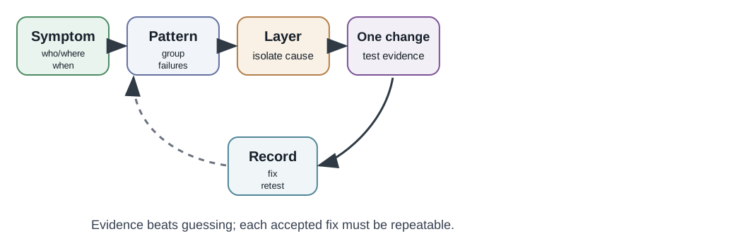
Use the first five minutes to capture:
- Which identifiers were missed, duplicated, unknown, or read in the wrong place.
- Which object type, tag type, attachment method, reader, antenna, and location were involved.
- Whether the issue affects every item, one item, one material, one reader, one antenna, one doorway, one time window, or one software event.
- What changed recently: tag batch, mounting, packaging, pallet pattern, reader firmware, antenna cable, power setting, middleware rule, or workflow.
- Whether the business problem is a physical read problem or an event interpretation problem.
Do not start by increasing power. That can hide the real issue, enlarge the wrong read zone, and create cross-reads.
9.6 Turn the Complaint Into Counts
When tags stop reading, the instinct is to blame the reader or the software. Far more often the cause is the RF link between antenna and tag: the tag is detuned by the object it is attached to, sitting in a field null, cross-polarized to the reader antenna, shadowed by packaging, or moving through the zone too quickly. The tell is that the failures are position-specific or material-specific. The same tag and reader may work in free air and fail on a particular carton, metal tool, liquid container, or presentation angle.
Start by turning the complaint into counts. “The dock reader is bad” is not evidence. A useful first record might say: during 50 carton passes, 38 produced accepted receiving events, 8 produced raw reads that middleware filtered out, 4 produced no raw reads, and 3 neighboring staged cartons were also observed. That record separates at least three problems: physical missed reads, event filtering, and wrong-zone reads. Each problem needs a different first test.
Then group the misses. If the 4 no-read cases are all foil-lined cartons, object material is a better first suspect than reader firmware. If they all pass antenna 2, the cable, port, antenna angle, or local reflections are better suspects. If every carton has raw reads but only 38 events appear, middleware timing and duplicate rules are the first boundary to inspect. A good troubleshooting summary therefore includes both raw observations and accepted business events, such as 50 expected passes, 46 raw-read successes, 38 accepted events, 8 filtered observations, and 3 wrong-zone reads.
This pattern-first habit prevents harmful fixes. Increasing power may turn the 4 misses into reads, but it may also raise wrong-zone reads from 3 to 12. Replacing all tags may hide a bad antenna port. Editing middleware may make a physical blind spot look like a clean event stream. The right first action is to preserve the symptom, identify the layer, and test one variable while watching for side effects.
9.7 Pattern Map
Use the pattern map to choose the first diagnostic branch.
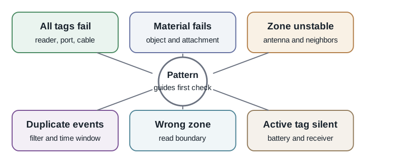
Common patterns:
- All tags fail at one reader: Check reader power state, antenna port, cable, region setting, inventory operation, and network path.
- One tag type fails everywhere: Check tag family, memory encoding, orientation, attachment, and compatibility with the reader operation.
- One object material fails: Check metal, liquid, body proximity, stacking, bending, cleaning, heat, and tag form factor.
- One doorway or shelf is unstable: Check antenna placement, cable, reflections, neighboring readers, shielding, and workflow motion.
- Many reads but poor events: Check middleware filtering, time windows, duplicate suppression, direction logic, and business rules.
- Wrong-zone reads: Check whether the RF field extends into staging, adjacent shelves, neighboring lanes, or return areas.
The first diagnostic question is not “What is the best tag?” It is “What does this failure pattern make unlikely?”
9.8 Layer Isolation
Troubleshooting should move from physical evidence to software interpretation.
9.8.1 Tag And Attachment
Check whether the tag is correct, encoded, attached, protected, and oriented as expected.
Useful tests:
- Read a known-good tag in a simple controlled location.
- Read the failing tag before and after attachment.
- Compare the same tag on the real object, on a spacer, and away from the object.
- Check whether the identifier, memory bank, and lock state match the process.
- Inspect damaged, bent, wet, overheated, dirty, or reused tags.
9.8.2 Object And Environment
Materials change tag behavior. Metal can detune or reflect. Liquids and body proximity can absorb or shift RF behavior. Stacking and dense packing can shadow tags. Movement can shorten the time available for a reliable read.
Useful tests:
- Test the real object, not only a sample tag in free air.
- Rotate and reposition the item through the intended path.
- Compare empty, full, wrapped, stacked, and cleaned conditions where relevant.
- Log misses and duplicates by material and mounting position.
9.8.3 Antenna And Read Zone
The antenna creates the read zone. A good read zone reads the intended object and suppresses nearby objects.
Useful tests:
- Sketch where reads should happen and where reads must not happen.
- Disable antennas one at a time to see which antenna creates the event.
- Move a test tag through the boundary of the zone.
- Check cable, connector, antenna port, mounting angle, and shielding.
- Verify that neighboring readers are not creating duplicate or wrong-zone events.
9.8.4 Reader Settings
Reader settings control inventory timing, antenna sequence, session behavior, power, reporting, and diagnostics. A setting change can fix one issue while creating another.
Useful tests:
- Export the accepted settings before changing them.
- Change one setting at a time.
- Record reader, firmware, region, antenna, and inventory settings with each test.
- Compare raw reads with middleware events after each change.
9.8.5 Middleware And Business Events
Raw reads are not business facts. Middleware decides how repeated reads become received, returned, moved, present, missing, or exception events.
Useful tests:
- Compare raw reader observations to the event stream.
- Check duplicate suppression, read windows, direction logic, and exception queues.
- Confirm that a missed business event is not only a filtered physical read.
- Verify unknown tags, duplicate identifiers, and retired identifiers.
9.9 Material, Orientation, and Event Evidence
Two material families break RFID in different ways, and the fix depends on band and mounting. Treat material behavior as evidence, not as a generic “bad tag” label.
| Situation | What happens | First fix to test |
|---|---|---|
| UHF tag on metal | Metal reflects and detunes the tag antenna, shifting it off band and creating nulls. | Use an on-metal tag with a ground plane, or stand the tag off the surface. |
| UHF tag on or near liquid | Water absorbs UHF energy, starving the tag of wake-up power. | Move the tag to a dry face and expect shorter range near liquids. |
| HF or NFC tag on metal | Metal induces eddy currents that absorb the magnetic field and detune the coil. | Add a ferrite layer between coil and metal. |
| Tag edge-on to the field | Tag antennas are directional; broadside presentation reads while edge-on presentation may not. | Control presentation angle or use circular-polarized reader antennas where appropriate. |
The unifying idea is detuning: a tag antenna is resonant at the operating frequency, and mounting it on metal, liquid, or certain plastics can shift that resonance off band. A tag that reads on the bench and dies on the product is often being detuned by the product.
Use a small controlled matrix instead of a hunch. For a metal tool checkout problem, test the same identifier in four states: free air, taped flat to the tool, mounted on a spacer, and mounted with an on-metal tag. If the log is 40 / 40 reads in free air, 6 / 40 reads flat on the tool, 32 / 40 reads on a spacer, and 40 / 40 reads with an on-metal package, the cause is no longer “RFID unreliable.” The evidence says the original mounting detuned the tag and the on-metal package fixed that boundary.
Do the same for read-zone problems. Move one known test tag through the intended path and the nearby no-read zone while logging reader, antenna, timestamp, raw identifier, and event result. If antenna A produces 20 / 20 intended doorway reads but also 9 / 20 staging-area reads, while antenna B produces 18 / 20 intended reads and 0 / 20 staging reads, the fix is likely antenna geometry, shielding, or zone logic, not a different tag family. Record the side effect: a lower-power or re-aimed antenna must not trade wrong-zone reads for missed intended reads.
Middleware tests need their own counts. A tag sitting in a portal for 4 seconds may produce dozens of raw observations. If 75 raw observations become one receiving event, duplicate suppression is working. If the same 75 observations become 12 receiving events, the duplicate window or event key is wrong. If 75 observations become no event, the read may be filtered by an unexpected antenna, direction, unknown-tag, retired-tag, or confidence rule. Troubleshooting is complete only when the physical record and event record agree.
9.10 Controlled Change Test
Do not change five things and then declare victory. A controlled change makes the fix reproducible.
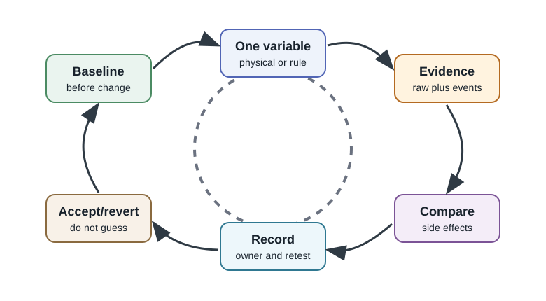
A controlled test includes:
- Baseline: Capture the symptom before changing anything.
- One change: Move one antenna, adjust one setting, change one tag position, or change one middleware rule.
- Evidence: Record raw reads, events, misses, duplicates, wrong-zone reads, and exceptions.
- Comparison: Check whether the original issue improved and whether side effects appeared.
- Decision: Accept, revert, or continue with a new single change.
- Record: Save the accepted setting, evidence, owner, and retest trigger.
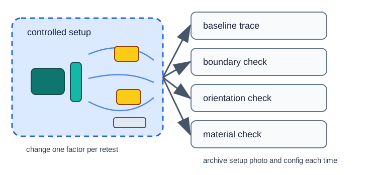
Good troubleshooting creates a record that another engineer can repeat.
9.11 Common Failures and First Checks
9.11.1 Missed Reads
Missed reads happen when intended tags are not observed or not turned into events.
First checks:
- Is the tag readable away from the object?
- Does the failure follow the tag, object, antenna, reader, or location?
- Is the tag shadowed, detuned, damaged, poorly oriented, or outside the read zone?
- Is middleware filtering the read out?
- Did a recent setting, firmware, cable, layout, packaging, or process change occur?
9.11.2 Duplicate Reads
Duplicate reads become a business issue when repeated observations create repeated events.
First checks:
- Are repeated raw reads expected while the tag remains in the zone?
- Is duplicate suppression using the right time window?
- Are multiple antennas or readers reporting the same movement?
- Does the business process need one event, one event per zone, or one event per direction?
9.11.3 Cross-Reads
Cross-reads happen when a reader observes tags outside the intended workflow.
First checks:
- Does the RF field reach staging, adjacent shelves, returns, or neighboring lanes?
- Which antenna reports the unwanted read?
- Can antenna placement, direction, shielding, or power reduce the zone without harming the intended read?
- Does middleware need a zone rule or direction rule?
9.11.4 Dense Tag Reads
Dense tag reads fail when the reader does not have enough time or configuration to inventory the population reliably.
First checks:
- Is the tag population larger or packed differently than the pilot?
- Does the reader have enough dwell time in the zone?
- Are antenna sequence and inventory settings appropriate for the population?
- Are items shadowing each other?
- Is the process expecting one fast pass when multiple passes or a different layout are needed?
9.11.5 Active Tag Issues
Active systems add battery, beacon, receiver, and location-evidence problems.
First checks:
- Is the tag awake, configured, and assigned to the right asset?
- Are receivers online and placed for the intended evidence?
- Are beacon settings, battery state, and decommissioning records up to date in the asset system?
- Does the business process treat a sighting as presence, approximate location, or proof of custody?
9.12 Nulls, Polarization, and Link Budget
A tag can fail right next to the antenna, which rules out a simple “not enough range” diagnosis. Two effects explain many near-field surprises. First, reflections from metal racks, frames, carts, and walls create standing-wave patterns with nulls: spots where the incident and reflected waves cancel and the field is weak even close to the antenna. Move the tag a few centimeters and it reads. Second, polarization mismatch can cut the link. A linear reader antenna and a linear tag antenna at 90 degrees can lose most of the coupling regardless of distance.
Underneath both effects is a two-way link budget. A passive read works only if the forward link delivers enough power to wake the tag and the reverse backscatter link is strong enough for the reader to decode. Detuning, absorption, nulls, and cross-polarization each reduce one or both links. That is why the right diagnosis is systematic: change angle, position, mounting material, polarization, or antenna sequence one variable at a time and watch which change restores the read.
A few numbers make the diagnosis less mysterious. UHF RFID around 900 MHz has a free-space wavelength near 300,000,000 / 900,000,000 = 0.33 m, so a quarter wavelength is about 0.33 / 4 = 0.0825 m, or 8.25 cm. Reflections from shelves, frames, and carts can therefore move a strong-read spot or a null by only a few centimeters. If a tag changes from unreadable to reliable after moving it 6 cm, that is consistent with a field-pattern problem.
Reader power also needs units. Raising conducted power from 27 dBm to 30 dBm is a 3 dB increase, roughly double the conducted power before antenna and regulatory limits. Doubling power can help marginal wake-up cases, but it also expands the field into nearby shelves and staging areas. If the baseline has 45 / 50 intended reads and 1 / 50 wrong-zone reads, and the higher-power test has 49 / 50 intended reads but 11 / 50 wrong-zone reads, the change is not acceptable without antenna, shielding, or middleware changes.
Dwell time closes the loop. A pallet crossing a 2.0 m useful read zone at 1.0 m/s stays in the zone for 2.0 / 1.0 = 2.0 seconds. If the reader cycles four antennas evenly, each antenna has roughly 2.0 / 4 = 0.5 seconds before the geometry changes. A dense-tag miss may be an inventory timing problem, not a tag defect. Good troubleshooting asks whether the selected power, antenna sequence, inventory behavior, duplicate window, and event rules all fit inside the actual motion of the workflow.
9.13 Quick Check: Detuning and Nulls
9.14 Example: Wrong-Zone Doorway Reads
A receiving doorway correctly reads tagged cases crossing the door, but it also reads cases waiting in a nearby staging area. The team first proposes more middleware filtering. That may help, but the diagnostic sequence should find where the unwanted read originates.
Evidence sequence:
- Capture raw reads by antenna and timestamp while moving one known test case through the doorway and staging area.
- Disable antennas one at a time to identify the antenna that sees the staging area.
- Sketch the intended read zone and unwanted zone.
- Test a physical change such as antenna angle, shielding, lower power, or relocation.
- Compare intended reads, missed reads, and wrong-zone reads.
- Add middleware zone rules only after the physical read zone is understood.
- Record the accepted layout, settings, middleware rule, and retest triggers.
The accepted fix may be physical, software, or both. The important point is that the team can explain why the event is now trustworthy.
9.15 Evidence Packet
A troubleshooting packet makes the fix auditable.
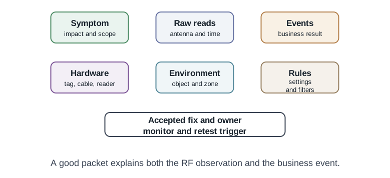
Include:
- Symptom, business impact, and affected workflow.
- Raw observations and business events.
- Tag model, object material, attachment, and representative photos or notes.
- Reader, antenna, cable, firmware, region, and settings.
- Middleware filtering, time window, event schema, and exception rules.
- Test steps, changed variables, results, and side effects.
- Accepted fix, owner, monitoring rule, and retest trigger.
9.16 Common Mistakes
- Changing reader power first: This may increase cross-reads and hide the root cause.
- Testing only a loose tag: The real object, material, and attachment can change behavior.
- Ignoring middleware: A physical read may be filtered out, duplicated, or mapped to the wrong event.
- Skipping raw-read evidence: Without raw reads, event problems are hard to separate from RF problems.
- Fixing one zone without checking neighbors: Antenna changes can create new wrong-zone reads.
- Treating active sightings as exact proof: Receiver layout and evidence model still need review.
- Forgetting retest triggers: Packaging, layout, firmware, tags, and business rules change over time.
9.17 Review Checklist
Before closing a troubleshooting issue, confirm:
- The failure pattern is described and scoped.
- Raw reads and business events were compared.
- Tag, object, antenna, reader, middleware, and process layers were considered.
- A known-good tag and representative failing object were tested.
- Only one variable was changed per accepted test.
- Side effects were checked, especially wrong-zone reads and duplicate events.
- The accepted fix, owner, monitoring rule, and retest trigger are recorded.
9.18 Knowledge Check
9.19 Match Symptoms to First Checks
9.20 Order the Troubleshooting Workflow
9.21 Summary
RFID troubleshooting is an evidence workflow. Start with the failure pattern, isolate the layer, change one variable, compare raw reads with business events, and record the accepted fix. The goal is not only to make the symptom disappear; it is to preserve a retestable explanation for why the RFID event can now be trusted.
9.22 Key Takeaway
RFID troubleshooting should isolate the layer first: tag, antenna, reader, environment, middleware, or application event handling.
9.23 Concept Relationships
- Tag and attachment connect the identifier to the real object and material.
- Antenna layout defines where reads are intended and where they become cross-reads.
- Reader settings shape inventory behavior and reporting volume.
- Middleware converts raw observations into business events and exceptions.
- Operations owns retest triggers when layout, packaging, firmware, tags, or business rules change.
9.24 References
This chapter was checked against official RFID and NFC standards context from GS1 EPC/RFID materials, the ISO/IEC 18000-63 standards page, and NFC Forum specifications. Treat standards and data sheets as starting points; troubleshoot with the actual tag, object, reader, antenna, firmware, and workflow.
9.25 What’s Next
- RFID Design and Deployment: turn troubleshooting findings into better pilot and rollout plans.
- RFID System Components: review readers, antennas, middleware, and event handoff.
- RFID Tag Types: revisit tag family, form factor, memory, and lifecycle choices.
- RFID Frequency Bands: connect material behavior to LF, HF, NFC, UHF, and active systems.