13 Packet Error Detection
Checksums, CRCs, Validation Scope, and Recovery Decisions
13.1 In 60 Seconds
Error detection checks whether a protected byte range still matches the sender’s check value. A checksum or CRC can reject corrupted bytes and drive a recovery action, but it does not repair the frame, explain the payload, or authenticate the sender.
13.2 Start With the Story
Start with a message crossing a link where the receiver must know where the packet starts, what each field means, and whether any byte was corrupted. The core idea in Packet Error Detection is simple: packet and format design is about boundaries, field meaning, compactness, checks, and the evidence that the receiver can parse the payload safely. This page focuses that idea on Packet reliability checksum and CRC roles, validation scope, residual risk, recovery behavior, and a repeatable error-detection review workflow. In everyday IoT, JSON, CBOR, Protobuf, custom binary, framing bytes, CRCs, and overhead budgets are practical choices with reliability and debugging costs. Start simple: draw the packet as fields, mark the payload and checks, then justify the format only after the parse path is clear.
13.3 What a Check Value Proves (and What It Doesn’t)
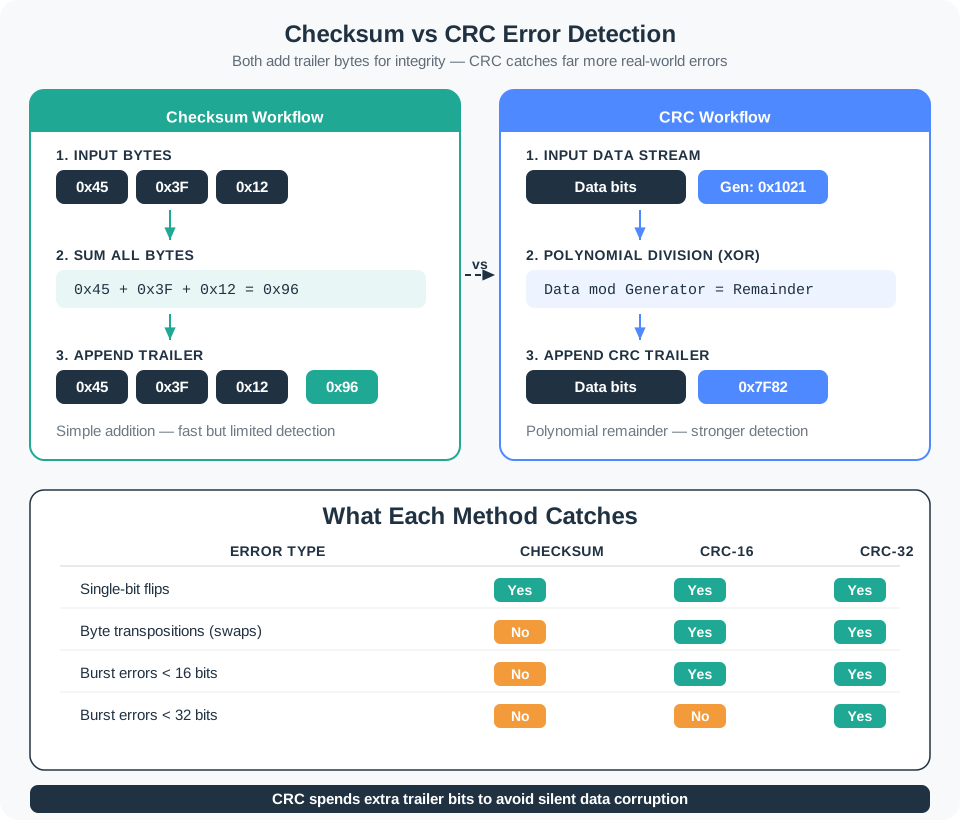
Packet error detection answers a narrow question: did the bytes that arrived match the bytes the sender intended to protect? The sender computes a small check value over a defined byte range and appends it. The receiver recomputes it and compares.
The important idea is to know the limits. A passing check gives the receiver evidence to accept, drop, retry, or escalate a frame. It does not explain what the payload means, correct the data, or prove who sent it.
If you only need the intuition, this layer is enough: a check value protects a specific byte range; both sides must compute it the same way; a match means those bytes passed this one test, nothing more.
Think of a tamper-evident seal on a parcel. A broken seal tells you something changed in transit, but it does not tell you what the contents should have been, and a maker could counterfeit the seal. A check value is the same: it flags accidental corruption, not meaning and not authenticity.
A practical receiver also keeps the check value tied to the packet boundary. In a Modbus RTU frame, for example, the CRC belongs to the address, function code, data bytes, and exact end of the frame; validating only the register value shown by a decoder would miss length, address, or byte-order mistakes. On an Ethernet link, the frame check sequence screens the delivered frame before higher layers interpret an IP packet or application message. In both cases, the check is useful because the receiver knows the covered bytes and the action to take when they fail.
The One-Minute Check-Value View
It protects a byte range
A record should always say exactly which bytes are covered: header, payload, length, or selected fields.
It detects, it does not correct
A failed check rejects the frame; the protocol still needs a recovery action such as drop or retry.
It is not authentication
A CRC catches accidental corruption. Deliberate tampering needs a keyed integrity tag, not a bigger CRC.
Beginner Examples
- A packet carries a one-byte checksum over the header and payload; the receiver adds the same bytes in the same order and rejects a mismatch.
- A framed link uses a CRC trailer; two devices that both say “CRC” still disagree unless the exact variant and protected range match.
- A security review finds an attacker can modify packets; a CRC still catches accidental corruption, but the design now needs an authenticated tag.
Check Value Knowledge Check
If you can name what a check value proves and does not prove, you can stop here. Continue to Practitioner to validate a real packet and pick a recovery action.
13.4 Apply It: Validate a Packet and Choose Recovery
The receiver should validate boundaries, scope, algorithm, and recovery in a repeatable order. The check value usually appears as a trailer or frame check sequence; the receiver recomputes over the protected bytes and compares.
Walkthrough: The Receiver-Side Check
- Confirm boundaries. Find the exact start and end of the frame before checking any value.
- Identify protected bytes. State whether the header, payload, length, trailer, or selected fields are included.
- Match algorithm parameters. Record width, polynomial or sum rule, initial value, reflection, final XOR, and transmitted byte order.
- Recompute locally. Use the captured bytes, not a decoded display value, to calculate the expected check.
- Compare and classify. A mismatch means reject; a match means only that the protected bytes passed this check.
- Choose recovery. Drop, retry, request a fresh sample, quarantine, or raise an alarm based on the system requirement.
Worked Example: A Tiny Checksum and Its Blind Spot
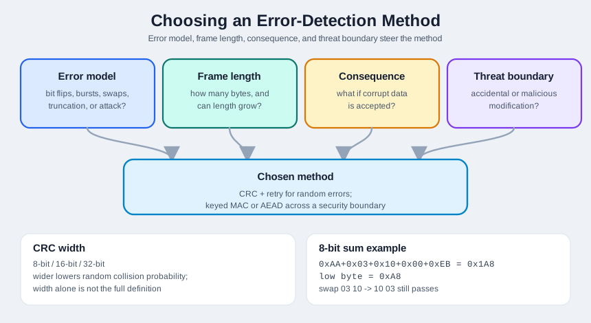
For the protected bytes AA 03 10 00 EB, an 8-bit addition checksum is 0xAA + 0x03 + 0x10 + 0x00 + 0xEB = 0x1A8, and the low byte is 0xA8. A complete review record makes the calculation reproducible:
Packet bytes:      AA 03 10 00 EB A8
Protected bytes:   AA 03 10 00 EB
Received check:    A8
Algorithm:         8-bit sum, low byte
Computed check:    A8
Decision:          accept for checksum demo only
Residual note:     byte swaps can still pass this checksum
Recovery on fail:  drop frame and request resend
Now swap 03 and 10. The sum is still 0x1A8 and the checksum still reads 0xA8, so the corrupted order passes. That blind spot is exactly why stronger links use a CRC, whose result depends on bit position and order.
Try It: CRC and Checksum Calculator
Enter bytes, then change one byte or swap two and watch how the addition checksum and the CRC respond differently. The CRC changes for reorderings that leave the simple sum unchanged.
Incremental Practice
Beginner
Take a packet layout and mark the bytes the check field should cover, then write one sentence on what it does not prove.
Intermediate
For a CRC trailer, list the full variant the receiver must know to reproduce the value from a capture.
Advanced
Decide whether a given link needs accidental-error detection only or authentication, and name the trigger for that decision.
CRC Parameter Knowledge Check
If you can validate a frame and choose recovery, you can stop here. Continue to Under the Hood for CRC parameters, method selection, and residual risk.
13.5 Under the Hood: CRC Parameters, Selection, and Residual Risk
A CRC treats the protected bits as a polynomial and divides by a generator polynomial; the remainder becomes the check value. That makes the result sensitive to bit position and ordering, which is why a CRC catches many error patterns an addition checksum misses. But “CRC” alone is not a specification.
Implementation details matter because many field failures are variant mismatches, not bad mathematics. A reflected CRC implementation processes least-significant bits first; a non-reflected implementation processes most-significant bits first. Some protocols transmit the low-order check byte first, while others transmit the high-order byte first. A receiver ported from one microcontroller library to another can therefore reject every clean frame if the polynomial notation, reflection flags, initial register, final XOR, or output byte order silently changes.
Selection also depends on what the protocol is trying to defend against. A small sensor link that mainly sees random bit flips can often use a CRC plus retry because the receiver only needs to screen accidental corruption. A gateway that crosses a security boundary needs a different layer: a keyed message authentication code, AEAD tag, or protocol-provided integrity check that an attacker cannot recompute without the key. A wider CRC lowers accidental collision risk for a stated model, but it does not create trust.
A useful implementation record names both the math and the operational decision. It should identify the CRC variant, the bytes covered, byte ordering on the wire, the comparison result, and the receiver action for mismatch. That record prevents a later port, library upgrade, or protocol bridge from changing one parameter while keeping the same label in the documentation.
The Parameters That Define a CRC
Width
The number of CRC bits, such as 8, 16, or 32. Wider usually lowers random collision probability, but width alone is not the full definition.
Polynomial
The generator polynomial. Different polynomials give different detection guarantees for different message lengths.
Initial value
The starting register value. A mismatch here makes both sides disagree even on clean bytes.
Reflection
Some variants process bits least-significant first, others most-significant first. A common implementation mismatch.
Final XOR
Some variants invert or transform the final remainder before sending it.
Byte order
The transmitted check field needs a defined byte order so the receiver compares the same value.
Avoid universal CRC claims. Do not write that a CRC catches a fixed percentage of all errors without stating the variant, the protected message length, and the error model. A useful review states what the chosen variant guarantees and what residual risk remains.
Choosing a Check Method
The choice is driven by the error model, frame length, failure consequence, and threat boundary.
For example, a battery sensor sending short binary frames over RS-485 might choose a CRC and a retry limit because noise, termination problems, and cable faults are the dominant failure modes. A firmware-update channel should not rely on that same CRC to accept code: it still needs a signed image or authenticated transport because the consequence is executing attacker-controlled bytes. The review question is not “which check value is strongest in isolation?” but “which failure can pass this check, and what layer catches it next?”
Good test vectors cover more than one happy path. Include the empty payload if the protocol permits it, the maximum-length payload, a one-bit flip, a burst error, a swapped-byte case, a truncated frame, and a frame with the right check value but the wrong address or length field. Those cases expose whether the implementation protects the intended byte range and whether the receiver rejects cleanly before any application action runs.
Common Pitfalls
- Verifying the wrong bytes. Do not compute over a decoded value, an omitted field, or an already-stripped region unless the protocol says so.
- Naming only CRC-16 or CRC-32. The width is not enough; record polynomial, initial value, reflection, final XOR, and byte order.
- Treating a match as proof of meaning. A pass means the protected bytes passed this check; the payload can still be stale, mis-scaled, or unauthorized.
- Forgetting recovery. A receiver that detects corruption but has no drop, retry, quarantine, or alarm policy still has an incomplete design.
Integrity Boundary Knowledge Check
At this depth, error detection is a receiver decision tool with explicit limits: it protects a stated byte range, screens for a stated error model, and leaves residual risk that the recovery policy and any authentication layer must cover.
13.6 Summary
- A sender computes a check value over a defined byte range; the receiver recomputes it and compares.
- Checksums are simple but can miss structured changes such as byte swaps and balanced edits.
- CRCs are stronger for accidental corruption, but only when both sides use the same variant and protected-byte scope.
- A CRC is defined by width, polynomial, initial value, reflection, final XOR, and byte order, not by its name alone.
- Detection is not correction; the protocol still needs a recovery action on failure.
- A CRC is not authentication; use a keyed integrity mechanism when deliberate modification is in scope.
Error detection finds corrupted data; it does not make the link reliable by itself. Choose parity, checksum, or CRC based on the likely error pattern and the consequence of accepting bad data, and always pair detection with a recovery action.
13.7 See Also
Packet Anatomy
See where headers, payloads, and check fields sit inside a frame.
Packet Framing
Learn how the receiver finds frame boundaries before validating any value.
Protocol Selection Framework
Decide when integrity and recovery requirements should shape protocol choice.