flowchart TD
  A["Microphone signal"] --> B["Sample and quantize speech"]
  B --> C["Encode with a voice codec"]
  C --> D["Group codec frames into packets"]
  D --> E["Send over constrained link"]
  E --> F{"Interactive enough?"}
  F -- "yes" --> G["Keep codec, packet size, and jitter buffer"]
  F -- "no" --> H["Rebalance bit rate, frame size, batching, or link"]
24 Voice and Audio Compression for IoT
Match Speech Codecs to Link Budget and Review Evidence
fundamentals
signal
processing
voice
24.1 In 60 Seconds
Voice compression turns a raw microphone sample stream into a stream small enough for constrained IoT links. Review it as a complete link-budget, packet-overhead, latency, loss, CPU, energy, and listening-validation decision.
24.2 Start With the Story
Start with a physical signal that is noisy, delayed, sampled, quantized, calibrated, filtered, packed, and finally sent as a number someone will trust. The core idea in Voice and Audio Compression for IoT is simple: signal processing is the bridge between the physical world and digital evidence, so every sampling, ADC, filter, and calibration choice changes the value that leaves the device. This page focuses that idea on Narrowband voice, PCM baselines, companding, speech codecs, packet overhead, DTMF, SS7 control planes, CTI/TAPI, TDM trunks, and latency. In everyday IoT, temperature drift, vibration spikes, audio snippets, and lab traces all become decisions only after their limits and uncertainty are made visible. Start simple: trace one measurement through the chain, keep the raw-to-processed evidence, and move advanced math into the deeper review only when the simple chain no longer explains the result.
Phoebe’s Field Notes: Why A Quiet Talker Needs Companding, Not Just 8 Bits

Phoebe’s Why
Sampling at 8 kHz answers how often a microphone voltage is read; it says nothing about how finely each reading is rounded. That second question sets a noise floor that is fixed in absolute volts, because a linear quantizer spends its 8 bits across the full electrical range every single sample, loud or quiet. A talker speaking close to the mic uses most of that range, so the rounding error is a small fraction of the signal. A talker speaking softly, or farther away, still gets rounded to the same fixed-size steps – so the same absolute error becomes a much bigger fraction of a much smaller signal. This chapter’s own line about linear quantization “wasting resolution on loud parts” is really this: the step size is sized for the loudest moment and then charged, in full, against every quiet one. Companding’s trick is to shrink the step size for quiet samples before quantizing, so quiet speech is not forced to share the loud talker’s ruler.
The Derivation
Sampling rate sets the Nyquist ceiling on content, independent of bit depth:
\[f_{max} = \frac{f_s}{2}\]
Quantizing an \(N\)-bit linear PCM word over a full-scale range spaces code steps by \(q\), and a uniform rounding error averages to an RMS noise of \(q/\sqrt{12}\), giving a full-scale signal-to-noise ratio of:
\[\mathrm{SNR}_{dB} = 6.02N + 1.76\]
Because the quantization noise floor is fixed by \(q\), not by how loud the actual signal is, a signal sitting \(L\) dB below full scale loses that same \(L\) dB of headroom one-for-one:
\[\mathrm{SNR}_{dB}(L) = 6.02N + 1.76 - L\]
Worked Numbers: This Chapter’s Own 8 kHz Baseline
- Nyquist ceiling at this chapter’s own 8 kHz rate: \(f_s/2=8{,}000/2=4{,}000\) Hz – exactly the “about 4 kHz” this chapter already states for the classic narrowband baseline.
- Full-scale SNR at the chapter’s own 8-bit, 64 kbps baseline: \(\mathrm{SNR}=6.02(8)+1.76=49.9\) dB.
- For contrast, the chapter’s own 16-bit, 128 kbps figure: \(\mathrm{SNR}=6.02(16)+1.76=98.1\) dB – doubling the sample width buys about 48 dB, not double the quality.
- A quiet talker, a realistic 40 dB below full scale (someone speaking softly, or farther from the mic than the level the link was calibrated for): \(\mathrm{SNR}(40)=49.9-40=9.9\) dB on plain 8-bit linear PCM – barely above the noise, which is exactly why an uncompanded 8-bit narrowband channel is not good enough on its own.
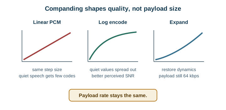
- Why companding fixes this without adding bits: mu-law and A-law compress large samples and expand small ones before quantizing, so the effective step size shrinks for quiet passages instead of staying fixed at the loud-talker size used above. The wire still carries 8 bits and 64 kbps; the same quantization-noise arithmetic is simply spent where quiet speech actually lives, which is this chapter’s own claim that companded 8-bit speech “sounds like more bits of linear PCM at the same bit rate.”
24.3 Why Voice Gets Compressed
Raw digital audio is bandwidth-hungry. Capturing speech as plain samples produces a steady stream of bits that can overwhelm the narrow, low-power links many IoT devices use. Voice compression shrinks that stream so speech fits the link.
The path is familiar from sampling: a microphone signal is sampled and quantized into numbers, and then compressed before it is packetized and sent. Compression sits after the same sampling and quantization steps covered in the ADC chapter.
If you only need the intuition, this layer is enough: voice compression trades exact fidelity for a stream small enough to fit a tight link, and the main levers are bit rate, audio quality, and end-to-end delay.
Lossy compression is the norm for voice. Unlike a file you must reconstruct exactly, speech only needs to stay intelligible and natural enough, so voice codecs discard detail the ear barely notices in exchange for a much smaller stream. Think of shorthand note-taking: you do not capture every word, only enough to reconstruct the meaning.
For example, a battery-powered site intercom may capture narrowband speech from a MEMS microphone, send it over Wi-Fi or LTE-M backhaul, and need a supervisor to understand a short spoken request with little delay. Raw 8 kHz, 16-bit, mono PCM is 128 kbps before packet headers, and classic 8-bit narrowband PCM is still 64 kbps. A speech codec such as AMR-NB, Opus configured for speech, or Codec2 can reduce the carried voice stream by modelling speech and tolerating small perceptual losses. The choice is not only the advertised codec bit rate; the device must also budget packet headers, jitter buffer delay, dropped packets, CPU energy, and whether the audio is live talk, a push-to-talk clip, or a stored alert.
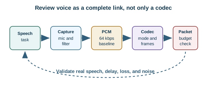
The One-Minute Voice-Coding View
Start from the link
The reliable, sustained bit rate sets the ceiling for the codec you can use.
Mind the delay
Interactive conversation needs low end-to-end latency, which limits how much audio you can batch.
Pick lossy, then validate
Choose a speech codec and confirm it sounds acceptable over the real link, not only on paper.
Beginner Examples
- Plain uncompressed speech samples can exceed what a narrow link comfortably carries, which is why phones compress.
- A one-way recorded alert tolerates more delay than a live two-way conversation.
- Working on bench wifi does not prove a codec works over a constrained field link.
Voice Compression Knowledge Check
If this gives you the trade-off, you can stop here. Continue to Practitioner when you need to choose a codec and packet size for a real link.
24.4 Apply It: Match the Codec to the Link
The practical job is to pick a codec and bit rate the link can sustain, size the packets to balance overhead against latency and loss, and confirm the result by listening over the real link.
A practical review starts with the worst hour of the deployment, not the best bench measurement. A Wi-Fi door station may have enough throughput but suffer roaming gaps and jitter when the access point is busy. An LTE-M tracker may have enough coverage for telemetry but limited uplink budget for live speech. A phone-tethered wearable may depend on BLE connection interval and app foreground behavior. For each case, test the same sentence, background noise, and packet-loss pattern with the candidate codec and packet size, then log perceived intelligibility, round-trip delay, and gaps.
Walkthrough: From Link Budget to Validated Audio
- Measure the link budget. Find the reliable, sustained bit rate and the typical packet loss of the real link, not the peak or the lab figure.
- Set the latency budget. Decide the maximum acceptable end-to-end delay; interactive talk needs far less than one-way playback.
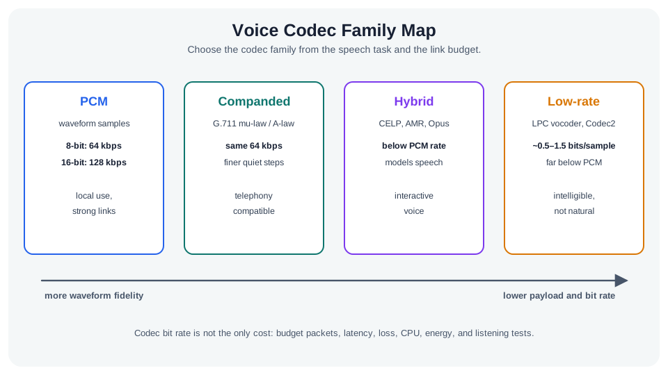
- Choose the codec family. Waveform coders preserve general audio at higher bit rates; speech-model coders reach much lower bit rates for voice specifically. Match the family to the content and the bit rate the link allows.
- Size the packets. Each packet carries header overhead, so very small audio packets waste bandwidth on headers, while large packets add delay and lose more audio per dropped packet.
- Plan for loss. Expect dropped packets on real links; prefer codecs and packet sizes that degrade gracefully, and consider packet-loss concealment.
- Validate with real speech. Listen to representative voices and conditions, because tone tests do not capture intelligibility or conversational delay.
The Packet-Sizing Trade-Off
Audio per Packet
Header Overhead Share
Latency
Audio Lost per Dropped Packet
Very small
High, headers dominate the bytes sent.
Low.
Small.
Moderate
Balanced against the payload.
Moderate.
Moderate.
Large
Low, overhead is amortized.
High.
Large.
There is no single best packet size, only a balance for your link’s bit rate, loss rate, and delay budget.
Incremental Practice
Beginner
For a one-way audio alert, explain why you can batch more audio per packet than for a live call.
Intermediate
Given a very low reliable bit rate, argue why a speech-model coder may be necessary and what content it assumes.
Advanced
Choose an audio-per-packet size for a lossy link and justify it against header overhead, latency, and per-loss audio.
Packet Sizing Knowledge Check
If your job is to choose a codec and packet size, you can stop here. Continue to Under the Hood for the baseline math and the coder families.
24.5 Under the Hood: From Samples to a Speech Model
The deeper layer explains the bit-rate baseline, how companding squeezes more from each bit, and how coders reach low rates.
Why Compression Works
Compression starts from redundancy. English text is not random: spaces, vowels, common letters such as E, T, A, O, I, and N, and repeated word patterns appear far more often than rare letters or unusual sequences. A compressor can spend short codes on common events and longer codes on rare events. Speech signals have similar structure across amplitude, time, and frequency. Adjacent samples are often related, voiced speech has periodic energy, and different frequency bands carry different amounts of intelligibility.
Voice codecs also exploit source knowledge. A speech source is shaped by the lungs, vocal folds, vocal tract, tongue, lips, and nasal passages, and the listener’s ear and auditory system do not treat every sample error equally. That does not mean a codec can throw away anything it likes; it means compression should be judged against the human task. The useful review dimensions are compression efficiency, reconstructed speech quality, algorithmic latency, error resilience on a lossy link, and computational complexity on the target device.
The PCM Baseline
Uncompressed linear PCM has a simple bit rate:
bit rate = sample rate x bits per sample x channels
The classic narrowband telephony baseline samples speech at 8 kHz with 8-bit samples on one channel:
8000 samples/s x 8 bits = 64,000 bits/s (64 kbps)
By the sampling rule, an 8 kHz rate represents content up to about 4 kHz, which is enough for intelligible speech though narrower than the full range of hearing. This baseline is the reference that compression improves upon.
Companding: More From the Same Bits
Speech has a wide dynamic range, and quiet passages still carry meaning. Linear quantization spreads its code steps evenly, wasting resolution on loud parts. Companding applies a logarithmic curve before quantizing and the inverse curve after, giving quiet sounds finer steps. The two classic companding laws let 8-bit companded speech sound like more bits of linear PCM at the same bit rate.
In G.711 terms, mu-law and A-law are the two logarithmic companding rules used for narrowband PCM telephony. Both map a larger internal sample range into an 8-bit transmitted code word, then expand it at playback. Mu-law is commonly associated with a 14-bit two’s-complement input range before companding, while A-law is commonly described from a 13-bit signed input range; the operational point is the same for a connected product review: the wire still carries a 64 kbps channel, but the quantization steps are spent where speech perception needs them most.
Digital Telephony Baseline
Classic digital telephony is a useful baseline because it separates the data plane from the control plane. The data plane is the sampled speech stream: one narrowband channel at 8 kHz and 8 bits/sample is a 64 kbps voice channel before packet headers. Mu-law and A-law are the classic companding laws that make those 8-bit samples more useful for speech than uniform linear steps. T1 and E1 trunks then schedule many of those voice channels into fixed time slots with time-division multiplexing, rather than dedicating one analog path per conversation.
The control plane carries the evidence that sets up or steers the conversation. DTMF dialing is the compact example: each keypad symbol is encoded as one low-group tone and one high-group tone, so switching equipment or an IVR can recognize digits without interpreting speech. For IoT voice and audio systems, this distinction is still practical: keep control events, call state, media packets, timestamps, and authentication evidence separate enough that audio loss does not silently become a command or routing failure.
Carrier telephony made that split explicit in SS7, the signaling system used around the public switched telephone network. A service switching point attaches phones and call paths, a signal transfer point routes signaling messages through the control network, and a service control point hosts service logic or database lookups. The useful IoT transfer is not the acronym set; it is the habit of asking which component carries media, which component routes control evidence, and which database or policy service is allowed to change the session.
Toll-free and emergency services show why that control plane is more than call setup. A dialed 1-800 number can be translated through a service database before the voice path is connected, so the caller’s digits, the lookup result, and the media circuit are separate evidence streams. Vertical service codes such as *69, *66, and *60 follow the same pattern: a small user command changes switch behavior only if the service record and policy allow it. Enhanced 911 adds the public-safety version of the lesson by routing a call toward the right public safety answering point and address record, often through Master Street Address Guide style data. A 108-style emergency service such as GVK EMRI makes the same architecture visible outside the US: the short code, call-center screen, ambulance dispatch, medical triage, police or fire handoff, and callback record are one safety workflow, but each field has a different owner and failure mode. For IoT designs, this is the warning against “solutions looking for problems”: powerful service logic must expose the problem it solves, the database it trusts, and the failure mode when the lookup is stale, unavailable, or routed to the wrong authority.
The later computer-telephony shift moved some service logic away from large carrier switching platforms from vendors such as Nortel, Siemens, Ericsson, Lucent/Bell Labs, and NTT and toward PCs, servers, and application APIs. Computer telephony integration, including TAPI-style interfaces, let software coordinate call state with message machines, interactive voice response menus, and call-center workflows. For connected products, treat a voice prompt, keypad digit, support script, or dashboard button as a control action with an owner, log, timeout, and fallback path, not merely as audio.
That shift also explains why simple answering machines matter in an IoT course. A local recorder with remote playback became a network service that can store a message, notify another endpoint, expose a directory, route a caller through an IVR, and attach the result to a customer record. Modern unified-communications systems bundle voice, email, video, presence, directory services, data, and mobility around the same session evidence. Call centers and CRM systems then add queues, agent screens, support scripts, outsourced handoff, and 411-style directory assistance. The design lesson is to keep the voice path, the control event, the identity record, and the business workflow explicit, because a support operator or automation service should see enough evidence to help without silently gaining access to unrelated device telemetry.
A caution follows from the same CTI path: once software owns the voice interface, release evidence must include more than audio quality. A speech interface often chains voice activation, speech recognition and transcription, intent interpretation, data lookup, and spoken response. Each stage needs a failure budget: noise immunity and low power at activation, recognition accuracy for real callers, intent confidence and escalation rules, query authorization, and response confirmation. A 99.999% availability target still allows about five minutes of annual downtime, so emergency and public-safety voice paths cannot treat a cloud IVR, carrier route, or call-center integration as always available. 911 outages and phone-compromise scenarios belong in the review as explicit drills: verify fallback dialing, local instructions, callback identity, audit logs, least-privilege support screens, and a security path for suspected PBX, handset, or account takeover.
Lossless Versus Lossy
Lossless coding reconstructs the exact samples but achieves only modest, data-dependent compression, so it rarely fits tight voice links. Lossy coding discards perceptually minor information for much larger savings and is the norm for voice.
Two Ways to Be Lossy
Coder Family
What It Sends
Bit Rate
Trade-Offs
Waveform coder
An approximation of the waveform, often by predicting each sample and coding the smaller error.
Below PCM, with modest complexity.
Handles general audio; less aggressive savings.
Parametric (speech-model) coder
Parameters of a vocal-tract model: filter coefficients, pitch, and excitation.
Far below PCM.
Assumes speech, adds complexity, can add artifacts.
A parametric coder reaches a low bit rate because it transmits a compact model and lets the receiver re-synthesize speech, rather than sending the signal itself. That is also why it distorts music or tones, which the vocal-tract model was never meant to represent.
Waveform coders improve on plain PCM without fully switching to a speech model. Adaptive differential PCM, or ADPCM, predicts the next sample, sends a quantized prediction error, and adapts the predictor and quantizer as the signal changes. If the prediction is good, the error needs fewer bits than the original sample. Subband ADPCM first splits the speech bandwidth into bands, often with quadrature mirror filters, then codes the bands separately so each band can use a rate and predictor that match its energy and perceptual value. These designs sit between simple waveform preservation and full parametric speech synthesis.
A parametric speech-production model goes further. It treats speech as excitation from a voiced pulse train or unvoiced noise source passing through a vocal-tract filter and a lip-radiation/output model. Linear predictive coding estimates that filter from recent speech samples, then sends parameters such as prediction coefficients, pitch, gain, and voiced/unvoiced state. The decoder reconstructs intelligible speech from the model parameters, which is why this family can reach very low rates but must be validated with real voices, accents, noise, packet loss, and device CPU limits.
The LPC review record should name what is being estimated, not only quote a low bit rate. A short speech segment is approximated as a weighted sum of previous samples plus an excitation term. The encoder estimates the prediction coefficients for an all-pole vocal-tract filter, the residual or source signal that drives it, and the gain of that excitation. A practical implementation often estimates pitch from the autocorrelation of low-pass filtered speech, marks voiced segments as periodic and unvoiced segments as noise-like, and solves the coefficient equations with efficient Toeplitz-matrix methods such as Levinson-Durbin recursion. This is the source-filter reason an LPC-style coder can spend roughly 0.5 to 1.5 bits per sample rather than sending every PCM sample.
Code-excited linear prediction, or CELP, keeps the LPC source-filter model but searches a codebook for an excitation vector that minimizes a perceptually weighted error after the pitch predictor and LPC synthesis filter. That idea sits behind many mobile speech codecs: the channel sends a compact description of model state and excitation instead of a full waveform. In an IoT review, names such as GSM full-rate, AMR, AMR-WB, EVRC, or EVRC-B should trigger the same questions: supported modes, selected bit rate, voice activity behavior, packet-loss concealment, CPU load, and whether the codec is being used only for speech-like audio.
Latency, Overhead, and Loss
- Frame latency. Block-based codecs process audio in frames, so the frame length, any look-ahead, and the processing time all add delay before a packet can be sent. This algorithmic delay is separate from network delay.
- Packet overhead. Each audio frame is small, so fixed per-packet headers can be a large fraction of the bytes on the wire; batching frames amortizes the header but raises latency and per-loss audio.
- Loss propagation. Coders that predict across frames can let one lost packet affect following frames until the decoder re-synchronizes; packet-loss concealment hides gaps, and codec and packet-size choices set how gracefully the link degrades.
Voice Quality Evidence
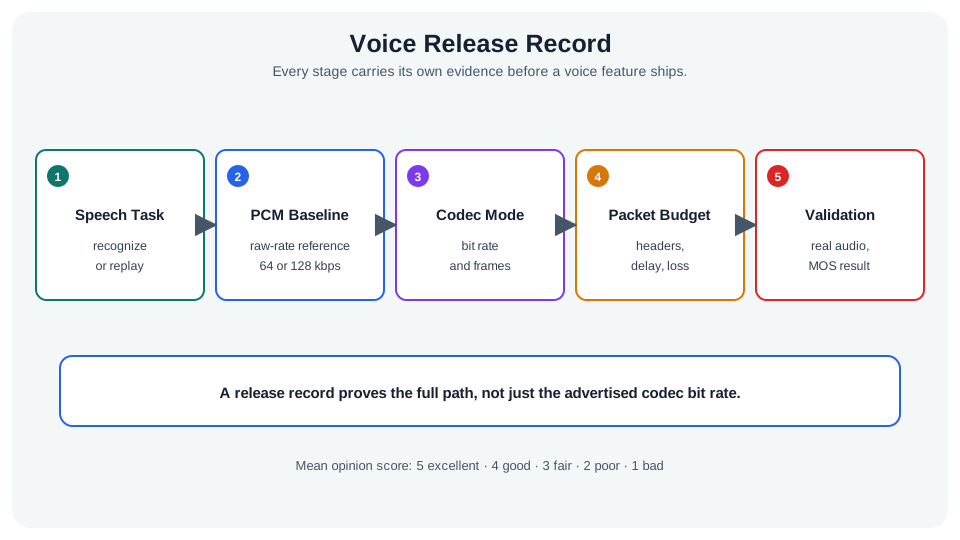
Voice quality is not proven by bit rate alone. Objective measures such as signal-to-noise ratio, segmental SNR, PESQ, and POLQA can compare a reference speech signal with a degraded output, but they still need listening context. The human-facing scale is often a mean opinion score, where 5 means excellent, 4 good, 3 fair, 2 poor, and 1 bad. A release record should say which language, talkers, background noise, packet loss, and device audio path were tested, because a codec that scores well in clean English lab speech may fail under accents, low-cost microphones, or wireless loss.
Variable-rate mobile codecs make that evidence especially important. EVRC-style operation can pair a high rate with voiced speech, lower rates with unvoiced or silence periods, and transitional rates with onsets, saving radio capacity while preserving intelligibility. AMR and AMR-WB modes make similar trade-offs across rates and bandwidths. The useful claim is therefore not “we use AMR” or “we use EVRC”; it is the selected mode set, the switching rule, the average data rate under realistic conversations, the MOS or objective-quality evidence, and the failure behavior when frame erasures rise.
VoIP Over Wireless
Packet voice adds protocol overhead around a small coded payload. A circuit-switched model dedicates capacity to a call, while a packet-switched model usually stacks codec output, presentation or payload framing, RTP, UDP, IP, MAC, and PHY behavior. That stack adds headers, algorithmic delay, packetization delay, arrival jitter, and fragmentation or goodput loss risk. Robust Header Compression, or ROHC, can make repeated IP/UDP/RTP headers much smaller on constrained wireless links, but the review should record the before-and-after header budget, compressor context, packet-loss tolerance, and recovery after long gaps or reordered packets. For wireless IoT products that carry voice, the packet budget should include the codec payload, RTP timestamp and sequence evidence, UDP/IP headers, link-layer retries, security overhead, jitter-buffer delay, and loss-concealment behavior.
The standards named in a voice design tell reviewers where to look. RTP itself is specified by RFC 3550, the basic audio/video profile by RFC 3551, AMR and AMR-WB RTP payload formats by RFC 4867, and EVRC-family RTP payload formats by RFC 5188. These references do not make a deployment correct, but they keep the record precise: the endpoint should identify the payload format it actually negotiates, the packet time it uses, the timestamp clock, and how receiver reports or application telemetry prove delay, jitter, and loss.
Common Pitfalls
- Validating on a tone or signal-to-noise figure instead of real speech. Objective tone metrics miss intelligibility and conversational delay.
- Ignoring algorithmic latency. A low-bit-rate codec can still feel laggy if its frames and look-ahead add delay.
- Forgetting per-packet overhead. For tiny audio frames, headers can dominate the link.
- Over-batching audio per packet. It cuts overhead but worsens latency and the impact of each loss.
- Using a speech-model coder for non-speech audio. Vocal-tract models assume speech and distort music or tones.
PCM Bit-Rate Knowledge Check
At this depth, voice coding is a budget problem: a PCM baseline set by sampling and bit depth, companding and lossy coding to shrink it, and a balance of bit rate, latency, overhead, and loss that only a real-link listening test can confirm.
24.6 Summary
- Voice compression shrinks a bandwidth-hungry audio stream so speech fits a narrow, often lossy, IoT link.
- The path is sample, quantize, then compress, and lossy coding is normal because speech only needs to stay intelligible.
- The classic narrowband PCM baseline is 8 kHz, 8-bit, single channel, which is 64 kbps before compression.
- Companding improves perceived quality at the same bit rate by giving quiet sounds finer quantization steps.
- Digital telephony keeps voice payloads, multiplexing, and control signals such as DTMF conceptually separate; SS7, toll-free lookup, vertical service codes, CTI/TAPI, IVR, enhanced 911 routing, unified communications, directory assistance, CRM-linked call centers, 911 fallback, and phone-compromise drills show why IoT audio designs should preserve that boundary across gateways, applications, and support workflows.
- Waveform coders reproduce the signal shape at moderate rates, while speech-model coders send vocal-tract parameters to reach much lower rates for speech only.
- Codec choice must balance bit rate, quality, algorithmic latency, packet overhead, and loss behavior, and must be validated with real speech over the real link.
Key Takeaway
Choose a voice codec and packet size from the link’s reliable bit rate, loss, and latency budget, remembering that lower bit rate, lower delay, and higher quality pull against each other, and confirm the choice by listening to real speech over the real link.
24.7 See Also
ADC Sampling Fundamentals
The sampling and quantization that produce the audio samples a codec compresses.
Signal Processing Essentials
Where audio coding sits among sampling, resolution, and validation decisions.