26 Radio Waves and Frequency Bands
Frequency, Wavelength, Obstacles, and Band Choice
26.1 In 60 Seconds
Radio band choice starts with wave behavior, not a headline range number. Frequency sets wavelength, wavelength shapes how antennas fit and how obstacles behave, and those physics determine whether a link can carry the required data through the real environment.
26.2 Start With the Story
Start with a sensor that works on the bench but fails after a wall, a shelf, interference, or a longer distance changes the radio path. The core idea in Radio Waves and Frequency Bands is simple: wireless propagation is about link margin, obstacles, frequency, fading, interference, antennas, and measured delivery rather than hope. This page focuses that idea on Wireless-propagation explaining frequency, wavelength, band families, obstacle interaction, antenna scale. In everyday IoT, RSSI, SNR, retries, packet delivery, placement, and fade margin explain why a gateway location or band choice succeeds or fails. Start simple: write the distance, band, obstacles, antenna assumptions, and measured margin before choosing the radio plan.
26.3 Why Frequency and Wavelength Decide the Link
Radio is how most IoT devices talk without wires. A transmitter pushes energy into an antenna, that energy radiates outward as an electromagnetic wave, and a receiver’s antenna captures a tiny fraction of it. Two linked numbers describe that wave: its frequency (how many times per second it oscillates) and its wavelength (the physical length of one oscillation in space). They are tied together by the wave’s speed, which in air is very close to the speed of light.
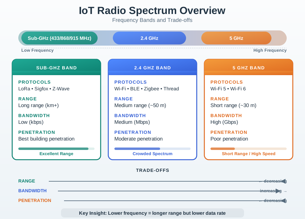
The single most useful intuition is this: a lower frequency means a longer wave, and a longer wave bends around and passes through everyday objects more easily and reaches farther for the same power. A higher frequency means a shorter wave, which can carry more data but is blocked, reflected, and scattered more by the walls and clutter of a real building.

26.3.1 Phoebe’s Why
A radio band is not just a label. The carrier frequency fixes the wavelength, and the wavelength becomes the physical ruler for the whole link. It sets the size of an efficient antenna, how strongly edges can diffract energy into a shadowed region, and how much free-space loss the receiver must overcome. Lower bands get longer waves, so they bend and penetrate better and ask for larger antennas. Higher bands get shorter waves, so they fit smaller devices and wider channels, but they pay extra loss at the same distance.
26.3.2 The Derivation
One cycle takes \(1/f\) seconds, so in that time the wave travels one wavelength:
\[\lambda = \frac{c}{f}\]
A quarter-wave antenna therefore scales as
\[L_{1/4} = \frac{\lambda}{4}\]
Power from an ideal transmitter spreads over a sphere:
\[S = \frac{P_t}{4\pi d^2}\]
An ideal receive antenna collects through an effective aperture:
\[A_e = \frac{\lambda^2}{4\pi}\]
So received power is
\[P_r = P_t\left(\frac{\lambda}{4\pi d}\right)^2\]
and free-space path loss is
\[\mathrm{FSPL} = \left(\frac{4\pi d f}{c}\right)^2\]
26.3.3 Worked Numbers: This Chapter’s Bands
Using \(c = 3.00 \times 10^8\) m/s:
- Sub-GHz near 900 MHz: \(\lambda = 3.00\times10^8 / 9.00\times10^8 = 0.333\) m, so \(L_{1/4} = 0.0833\) m \(= 8.33\) cm
- 2.4 GHz: \(\lambda = 3.00\times10^8 / 2.40\times10^9 = 0.125\) m, so \(L_{1/4} = 3.12\) cm
- 5 GHz: \(\lambda = 3.00\times10^8 / 5.00\times10^9 = 0.0600\) m, so \(L_{1/4} = 1.50\) cm
- Same-distance loss penalty: \(20\log_{10}(2400/900) = 8.52\) dB, \(20\log_{10}(5000/2400) = 6.38\) dB, and \(20\log_{10}(5000/900) = 14.9\) dB
The chapter’s band table follows directly: the sub-GHz antenna is about \(8.33/3.12 = 2.67\) times longer than the 2.4 GHz antenna, while a 5 GHz link starts with about \(14.9\) dB more free-space loss than a 900 MHz link at the same distance before walls, human bodies, or antenna detuning add their own losses.
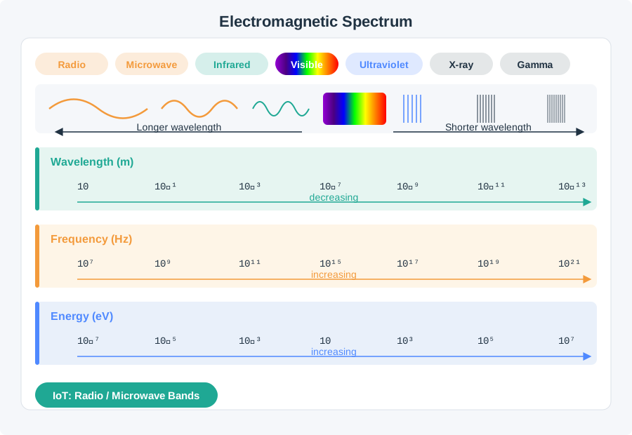
If you only need the intuition, this layer is enough: pick a lower frequency when you need range and obstacle penetration with modest data, pick a higher frequency when you need more data over shorter and clearer paths, and never trust a single datasheet “range” number for your real environment.
Think of sound. A deep bass note has a long wave and travels through walls and around corners, which is why you hear a neighbor’s bass but not their cymbals. A high hiss has a short wave and is easily stopped by a closed door. Radio behaves the same way: the long, low-frequency wave gets around and through obstacles, while the short, high-frequency wave is more easily stopped.
The same rule also explains why there is no universal best IoT band. A farm sensor, a hospital wearable, a Wi-Fi camera, and a millimeter-wave radar all value different parts of the trade-off. Good band choice starts by writing the job first, then choosing the frequency range whose wavelength, antenna size, and available bandwidth fit that job.
There is also a spectrum-placement idea underneath most radio systems. A sensor waveform, microphone signal, or digital bit stream starts as a baseband signal near zero frequency. A radio transmitter shifts that information onto a carrier so it can travel through an assigned channel and coexist with other users of the spectrum. Amplitude modulation varies the carrier’s strength; frequency modulation varies the carrier’s instantaneous frequency. Modern IoT radios use more efficient digital modulation, but the review habit is the same: separate the payload from the radio channel that carries it, then check occupied bandwidth, interference, receiver support, and regional rules.
Digital modulation applies the same idea to bits. Amplitude-shift keying (ASK) changes carrier strength, frequency-shift keying (FSK) chooses among carrier frequencies, and phase-shift keying (PSK) changes the carrier phase. Constellation diagrams are a compact way to show those choices: BPSK uses two phase points, QPSK uses four, and QAM combines phase and amplitude to carry more bits per symbol when the received signal is clean enough.
The One-Minute Band Decision
Name the link
Write down the distance, the environment (open field versus concrete building), and how much data each message carries.
Trade range against data
Lower frequencies favor range and penetration; higher frequencies favor data capacity and smaller antennas.
Respect antenna and region
A usable antenna must fit the enclosure at that wavelength, and the band must be legal where the device ships.
Beginner Examples
- A soil-moisture sensor across a large field, sending a few bytes per hour, favors a lower sub-gigahertz band for reach.
- A camera streaming inside a single room favors a higher band that offers more data capacity over a short path.
- A higher frequency is not simply “better.” It buys data capacity and small antennas at the cost of range and obstacle penetration.
Frequency Band Knowledge Check
If this gives you enough to reason about a band, you can stop here. Continue to Practitioner when you need to choose and defend a band for a real link.
26.4 Apply It: Choose a Band From the Link Requirement
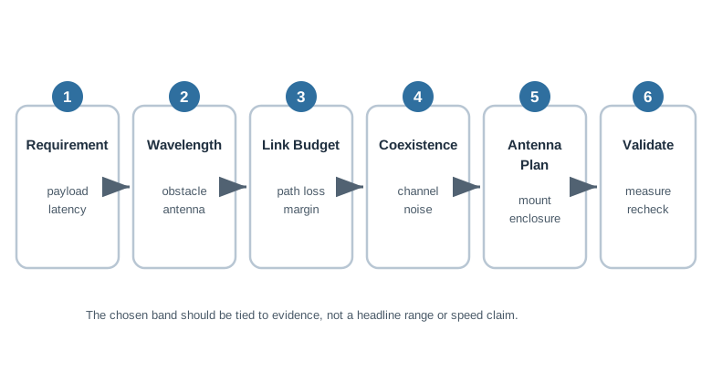
The practical job is to turn a link requirement into a defensible band choice and then prove it with a field test. The band sets your starting point for range, data rate, antenna size, and which obstacles will hurt the most.
Walkthrough: From Requirement to Defensible Band
- State the link. Distance, environment (open outdoor, light indoor, dense concrete, reflective urban), data per message and per second, power and battery limits, antenna space, and every regulatory region the product ships to.
- Translate data need into bandwidth need. More data per second generally needs more bandwidth, and wide bandwidth is easier to find at higher frequencies. Small, infrequent messages do not require a high band.
- Translate range and obstacles into a frequency direction. Longer range and heavier obstruction push toward lower frequencies; short, clear paths tolerate higher frequencies.
- Check antenna feasibility. A resonant antenna scales with wavelength, so lower frequencies need physically larger antennas. Confirm an adequate antenna and ground plane fit the enclosure.
- Confirm regional availability. License-free bands and their power rules differ by region; do not assume a band used in one country is legal or identical elsewhere.
- Validate in the field. Measure received signal and successful delivery in the real environment, at the real mounting position, with the production antenna and enclosure. Datasheet range is usually a best-case, open-air figure.
Worked Example: Antenna Size From Wavelength
Wavelength follows a simple relationship, where c is the wave speed (about 3 x 10^8 m/s in air):
wavelength = c / frequency
A common resonant element is about a quarter of the wavelength. Lower frequencies therefore need larger antennas.
These are example frequencies used to show the scaling. The exact bands you may legally use, and at what power, depend on your region.
Incremental Practice
Beginner
For a battery sensor sending a few bytes per hour across a warehouse, justify a sub-gigahertz choice in one sentence.
Intermediate
For a wearable with a 2 cm antenna budget, explain why 2.4 GHz is more feasible than a sub-gigahertz band.
Advanced
Take a vendor “range up to” claim and list the environmental assumptions you must field-test before trusting it.
Band Selection Knowledge Check
If your job is to choose a band and prove it works, you can stop here. Continue to Under the Hood for the mechanisms behind the trade-off.
26.5 Under the Hood: Wavelength, Obstacles, and Antennas
The deeper layer explains why the band trade-off exists. Each behavior comes from how a wave of a given length interacts with objects of a given size.
Wavelength and Frequency
Wavelength and frequency are inversely related through the wave speed:
wavelength = c / frequency
Because c is essentially fixed, doubling the frequency halves the wavelength. Wavelength is the yardstick that decides how a wave meets an object of a given size, which is why it, and not frequency alone, governs propagation behavior.
How Waves Meet Obstacles
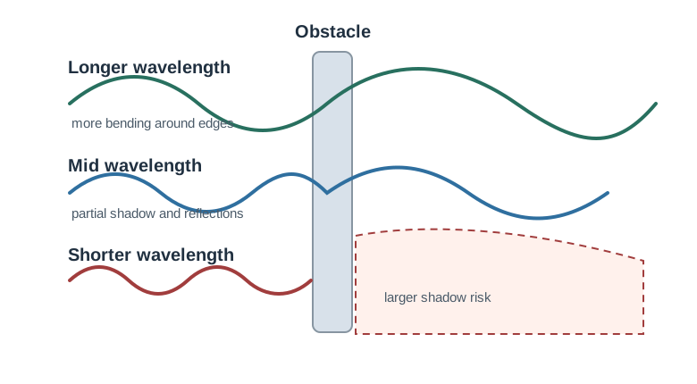
- Reflection happens off surfaces that are large and smooth compared with the wavelength, such as walls, metal, and the ground. Reflections create copies of the signal that arrive by different paths, which is the root of multipath fading covered in a separate chapter.
- Diffraction is the bending of waves around edges and corners. Longer wavelengths diffract more, so lower frequencies reach into the shadow behind an obstacle more effectively.
- Scattering occurs off objects and roughness comparable to or smaller than the wavelength, such as foliage and rain, spreading energy in many directions.
- Penetration and absorption attenuate a signal passing through a material. Loss generally grows with frequency, and water-rich materials, including people, absorb strongly. This is a major reason higher bands struggle indoors.
Line of Sight Is Not the Whole Story
Even with a clear line of sight, the wave needs clearance in an elliptical region around the direct path called the first Fresnel zone. Obstacles that intrude into this zone cause loss even when the two antennas can “see” each other. The zone is widest near the midpoint of the link and is larger at lower frequencies.
In clear conditions, received power also falls with distance, and for a fixed distance the free-space loss is higher at higher frequencies. The full accounting of path loss, antenna gains, and margins belongs to the link-budget chapter; the takeaway here is that a higher frequency starts with a propagation penalty that the rest of the design must pay for.
Antennas Are Tuned to Wavelength
- A resonant antenna’s size scales with wavelength. Common forms are about a half wavelength (a dipole) or a quarter wavelength (a monopole over a ground plane), so a lower frequency needs a larger efficient antenna.
- A quarter-wave monopole depends on a ground plane; a small or missing ground plane detunes it.
- Nearby metal, the enclosure, a battery, or a human hand shifts the resonant frequency and lowers efficiency, so the antenna must be tuned in its final mechanical context, not only on the bench.
- The polarization, or orientation, of the transmit and receive antennas should match; a large mismatch loses signal.
From Bits to RF and Back
A radio does not put application bits directly into the air. The transmitter first maps bits into a baseband waveform, shapes the pulses so the signal fits its channel, converts the waveform to analog form, filters unwanted content, mixes or synthesizes it up to the assigned carrier frequency, then drives the antenna through a power amplifier. The receiver does the reverse job: a low-noise amplifier and band-pass filtering protect the wanted channel, mixing brings the signal back toward baseband, filtering and sampling recover the waveform, and demodulation plus any equalization or error handling turns it back into bits.
The modulation choice changes both data rate and robustness. Simple schemes such as ASK or FSK can be cheap to implement but spend bandwidth or tolerate interference differently. Denser PSK and QAM constellations can move more bits per symbol, but the receiver needs enough signal-to-noise margin to distinguish nearby points; otherwise a high-rate mode becomes less reliable than a slower, more robust one.
This chain is why a wireless review separates payload, occupied bandwidth, carrier frequency, filtering, amplifier limits, antenna pattern, and regulatory channel plan. A modulation choice can be correct while the pulse shaping spills energy into a neighbor channel, a power amplifier can be legal only with the selected antenna gain, and a receiver can fail because filtering or overload rejects the wanted signal before software sees any packet.
Antenna Pattern Is Part of the Link
Omnidirectional antennas spread energy around a broad plane and fit many access-point, gateway, and wearable cases where device orientation is uncertain. Directional antennas such as Yagi or parabolic designs concentrate energy into a narrower region, increasing useful gain in that direction while making alignment, sidelobes, and coverage holes part of the deployment evidence. Choosing an antenna is therefore not only a range question; it is a coverage-shape question tied to user orientation, mounting height, polarization, and the areas the design must deliberately exclude.
Obstacle Interaction Reference
Common Pitfalls
- Treating higher frequency as strictly better. It adds bandwidth and shrinks antennas but pays in range and penetration.
- Trusting datasheet range. Published range is usually open-air, line-of-sight, best case, which a real building will not match.
- Ignoring the antenna’s mechanical context. Enclosure, ground plane, and nearby metal can detune a good antenna into a poor one.
- Assuming a band is legal everywhere. License-free allocations and power limits differ by region, so a working prototype can be non-compliant elsewhere.
- Claiming line of sight is enough. Obstacles inside the first Fresnel zone still cause loss.
Antenna Scaling Knowledge Check
At this depth, a band is a bundle of physics: wavelength sets antenna size, decides reflection, diffraction, scattering, and penetration, and drives the free-space loss the link budget must cover. A defensible band choice records each of these instead of treating “higher” or “lower” as automatically better.
26.6 Summary
- Frequency and wavelength are inversely linked by
wavelength = c / frequency, and wavelength decides how a wave meets objects. - Lower frequencies (longer waves) reach farther and penetrate and diffract around obstacles better, but offer less data capacity and need larger antennas.
- Higher frequencies (shorter waves) carry more data with smaller antennas, but lose range and are blocked, reflected, and scattered more.
- Obstacles act through reflection, diffraction, scattering, and absorption, all judged relative to the wavelength.
- A resonant antenna scales with wavelength and must be tuned in its real enclosure, with a proper ground plane and matched polarization.
- Band choice must respect the shipping region’s rules, and every range claim should be confirmed by a field test rather than a datasheet.
26.7 Key Takeaway
Choose a band by trading range and obstacle penetration, which favor lower frequencies, against data capacity and antenna size, which favor higher frequencies, and then prove the link in the real environment.
26.8 See Also
Path Loss and Link Budgets
Turn the band's propagation penalty into a quantified link budget and fade margin.
Fading and RF Interference
See how reflection and multipath become fading, and how interference differs from a weak signal.
Wireless Propagation Lab
Practice measuring real range and signal behavior instead of trusting datasheet numbers.