35 Stationary WSN Fundamentals
stationary WSN fundamentals, fixed wireless sensor network review, stationary sensor placement, WSN energy hole review, WSN coverage evidence, fixed sensor network design
35.1 Start With the Field Story
Stationary WSNs look simple because the nodes do not move, but the environment still does. Start with the sensing claim, then check coverage, sink placement, relay burden, maintenance access, and what changes would force a retest.
35.2 In 60 Seconds
A stationary wireless sensor network fixes sensor nodes, sinks, gateways, relays, and antennas in known locations. This makes coverage, routing, maintenance, and calibration easier to reason about, but it also makes placement mistakes persistent. A missed coverage area, weak link, overloaded relay, blocked enclosure, or inaccessible node remains a problem until someone changes the deployment.
Stationary WSN review is therefore a fixed-placement evidence process. The design is acceptable only when the sensing claim, node placement, coverage evidence, connectivity evidence, sink placement, relay burden, power assumptions, failure visibility, maintenance route, fallback action, and retest trigger are all recorded for the installed environment.

Phoebe’s Why
This chapter’s evidence record keeps asking for “antenna orientation” and “enclosure” as fixed, checkable facts – and that is only possible because a stationary node lets a reviewer measure the antenna’s actual clearance once and trust it forever. What that clearance has to satisfy is a real physical boundary: close to any antenna there is a near-field zone where the radiating pattern has not yet settled into the clean lobes a gain figure describes, because reactive energy sloshes back and forth between the antenna and anything nearby – a mounting bracket, a metal enclosure wall, another antenna – instead of radiating cleanly away. Only past a calculable distance does the field organize into the far-field pattern that “coverage angle,” “gain,” and “path loss” actually describe. A mobile node cannot promise that clearance stays constant; a bolted-down node can, which is exactly why this chapter treats mounting distance as evidence worth recording rather than a risk that needs continuous monitoring.
The Derivation
The Fraunhofer (far-field) distance for an antenna of largest physical dimension \(D\) at wavelength \(\lambda\):
\[R_{ff} = \frac{2D^2}{\lambda}\]
Inside \(R_{ff}\), radiation-pattern and gain measurements are not valid; a gain figure or a free-space path-loss model only describes the field beyond this boundary. Since \(\lambda = c/f\), a larger antenna or a lower frequency both push \(R_{ff}\) farther out:
\[R_{ff} = \frac{2D^2 f}{c}\]
Worked Numbers: Mote vs. Gateway Antenna Clearance
- Compact leaf-node antenna (catalog-typical 5.00 cm PCB monopole/dipole on a 2.4 GHz mote, \(\lambda = 0.125\) m): \(R_{ff} = 2(0.0500)^2/0.125 = 0.0400\) m \(= 4.00\) cm – a small clearance that a properly ventilated enclosure wall can usually satisfy
- Directional sub-GHz gateway antenna (catalog-typical 30.0 cm Yagi/panel at 900 MHz, \(\lambda = 0.333\) m): \(R_{ff} = 2(0.300)^2/0.333 = 0.540\) m \(= 54.0\) cm – more than ten times the mote’s clearance, because gain-oriented antennas trade a larger physical aperture for that gain, and aperture size enters \(R_{ff}\) squared
- The mounting consequence: installing that gateway antenna 20 cm from a metal utility-cabinet wall keeps it inside its own near field, where the manufacturer’s dBi rating, and any free-space or log-distance path-loss estimate built from it, is not yet a valid description of the radiated pattern
- Why “fixed” matters here: because \(R_{ff}\) scales with \(D^2\), a higher-gain antenna needs proportionally more clearance – exactly the kind of one-time, verifiable mounting fact this chapter’s placement-evidence record is built to capture, and exactly the kind of fact a moving node cannot guarantee stays true
35.3 Learning Objectives
By the end of this chapter, you will be able to:
- explain when a stationary WSN is a good fit and when mobility should be considered
- review fixed node placement for sensing meaning, coverage, connectivity, energy, and maintenance
- identify energy-hole, hotspot, coverage-hole, and partition risks without relying on brittle numeric shortcuts
- build a stationary WSN evidence record with accepted limits, fallback actions, owner, and retest trigger
- connect stationary WSN design to mobile WSN, energy management, routing, and coverage review chapters
35.4 Stationary WSN Fundamentals
35.5 Prerequisites
This chapter builds on WSN Introduction, Mobile WSN Fundamentals Review, MWSN Nodes, Sinks, and Data MULEs Review, WSN Communication Patterns, WSN Energy Management, WSN Routing Introduction, and WSN Coverage Fundamentals.
If a learner cannot describe sensing claims, node roles, gateway boundaries, coverage, route state, relay burden, duty cycling, buffers, and maintenance ownership, review those chapters before accepting a stationary WSN design.
35.6 Stationary Review Scope
Stationary WSN review starts with the reason nodes should stay fixed. Fixed placement is useful when the monitored condition is tied to known locations, but every placement assumption must be verified.
Sensing claim State what physical condition must be measured, where it is valid, how fresh it must be, and what decision uses the result.
Placement evidence Record node location, mounting, sensor exposure, enclosure, antenna orientation, calibration state, and environmental constraints.
Coverage evidence Show which areas, assets, or route segments are covered, uncertain, redundant, or outside the claim.
Connectivity evidence Record link quality, relay paths, sink reachability, reverse-link behavior, retries, and what happens when a path fails.
Relay and power evidence Review relay burden, wake schedules, battery or power source, replacement access, and hotspots near sinks or gateways.
Operations loop Name the owner, monitoring signal, fallback action, uncertainty rule, replacement rule, and retest trigger.
35.7 Fixed Placement Evidence Map
Use Figure 35.1 to keep fixed placement tied to the evidence it must produce.
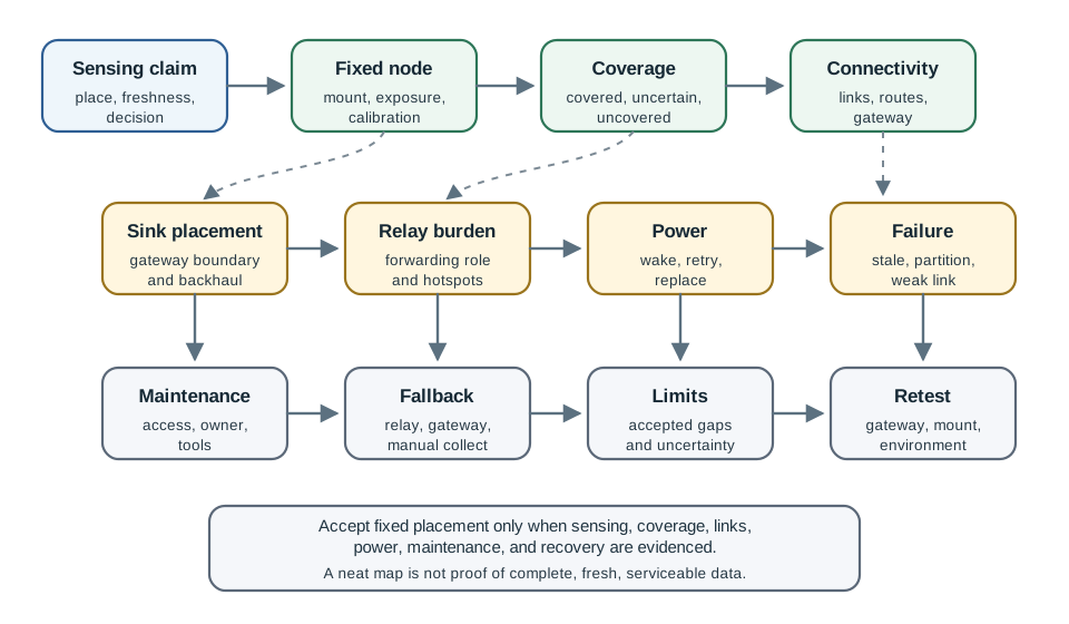
The map prevents a common mistake: treating stationary placement as finished once the nodes are installed. Fixed topology makes evidence easier to collect, but it also makes failures persistent. If a relay hotspot, coverage hole, obstructed sensor, or inaccessible battery is not visible in the record, the deployment can look stable while its data quality is drifting.
Use Figure 35.2 as a reminder that fixed placement still needs measured radio evidence. The figure is a stationary-source RSSI heatmap; the exact dBm values are example measurements, but the review pattern is general: preserve strong, weak, uncertain, and accepted areas instead of treating the planned position as proof of usable connectivity.
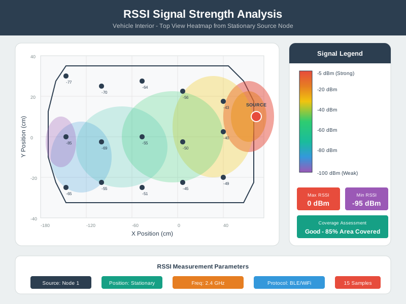
The fixed map is an index into evidence, not the evidence itself. A node position may stay correct for years while link quality, enclosure exposure, crop canopy, traffic mix, or maintenance access changes after one season, one equipment move, or one gateway relocation.
35.8 Stationary Design Proof Limits
Predictable topology Fixed nodes can make routes easier to inspect. They do not prove reliability unless link quality, reverse paths, retry behavior, and route repair are recorded.
Repeatable sensing A fixed sensor can compare the same place over time. It still needs mounting, exposure, calibration, drift, and physical access evidence.
Coverage planning Planned placement can reduce blind spots. It cannot prove coverage unless the review ties sensing range, obstacles, redundancy, and uncertain areas to the claim.
Energy planning Stable routes can make energy review easier. They can also concentrate relay work near sinks, gateways, or chokepoints.
Maintenance planning Known locations can simplify replacement. They can also create hard-to-service nodes if access, safety, and ownership are not reviewed.
Baseline comparison Stationary design gives a stable baseline for mobile alternatives. It does not prove that mobility is unnecessary unless fixed design risks are accepted.
35.9 Evidence Record
Use Figure 35.3 to turn fixed-placement assumptions into an auditable stationary WSN decision.
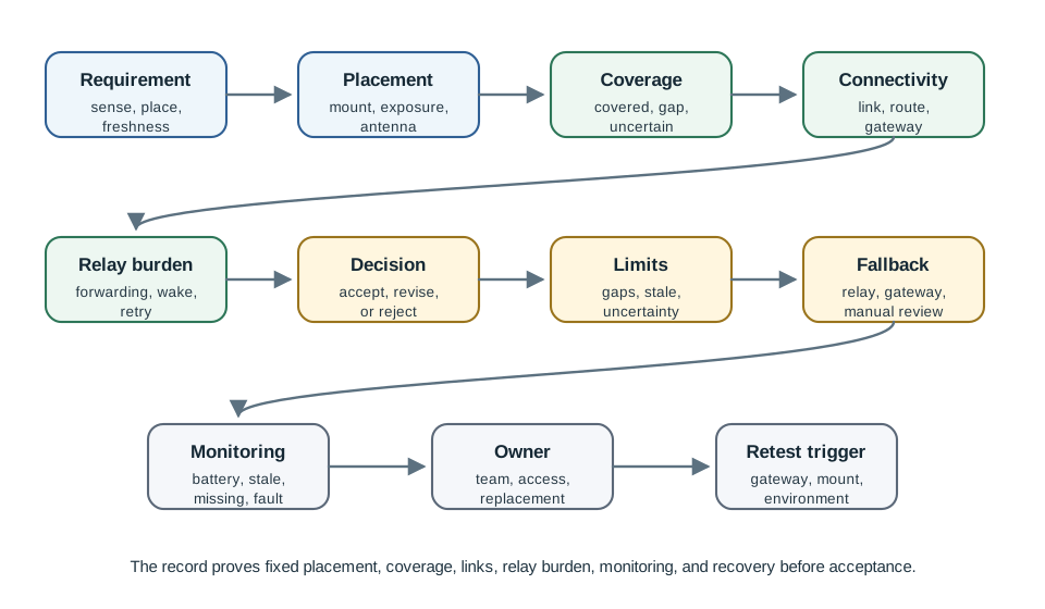
Requirement: Record the sensed condition, location meaning, freshness need, tolerated gaps, and decision that uses the reading.
Placement assumptions: Record node positions, mounting, sensor exposure, antenna orientation, sink placement, gateway boundary, and access constraints.
Observations: Record coverage checks, link evidence, route traces, relay burden, power state, sensor calibration, failure signals, and maintenance access.
Decision: Accept, revise, or reject the fixed deployment for this monitoring claim and operating environment.
Operations: Name owner, monitoring signal, fallback action, uncertainty rule, replacement rule, and retest trigger.
35.10 Reviewing Placement and Coverage
Fixed placement is not just a map. It is a claim about what each sensor can observe from a specific physical position.
Location meaning Record whether the reading describes a point, surface, zone, asset, route segment, volume, or inferred area.
Sensor exposure Review airflow, vibration, moisture, light, contact pressure, line of sight, enclosure effects, and interference from nearby equipment.
Coverage boundary Mark covered, redundant, uncertain, and uncovered areas. Do not let a placement diagram imply coverage that was not checked.
Retest condition New equipment, walls, crops, weather exposure, antenna position, gateway movement, or mounting changes can invalidate coverage evidence.
35.11 Reviewing Connectivity and Relay Burden
Stationary WSNs often use fixed multi-hop paths or stable neighbor sets. That stability can make operations easier, but it can also hide relay pressure.
| Property | Evidence made reusable by fixed topology | Retest trigger |
|---|---|---|
| Routing | Parent choices, route traces, reverse paths, and retry patterns can be checked against known node positions. | Node failure, gateway move, new obstruction, channel change, or repeated route repair. |
| Scheduling | Wake windows and TDMA-style slots can be planned around a stable neighbor set and known traffic pattern. | Added node, removed node, changed sampling period, relay overload, or unexpected collisions. |
| Localization | Surveyed positions, mounting height, orientation, and sensor exposure can be reused for later reviews. | Remounting, enclosure change, calibration drift, crop growth, equipment move, or access change. |
| Coverage | Covered, redundant, uncertain, and uncovered areas can be marked against a fixed physical layout. | Obstacle, environment, asset layout, sensing radius, or data-quality change. |
The strongest records separate planned topology from observed topology. Planned topology says where nodes, relays, sinks, and gateways should be. Observed topology says which neighbors were actually heard, which parent paths were selected, which nodes forwarded for others, which readings arrived stale or missing, and which physical areas stayed uncertain. The acceptance decision should cite the observed topology.
Link evidence Record delivery, reverse-link behavior, retries, channel state, antenna placement, enclosure effects, and link-quality trend.
Route evidence Record route traces, parent choices, failover path, route repair behavior, and whether data meaning changes through aggregation.
Relay burden Identify nodes that forward for others, especially near sinks, gateways, chokepoints, and narrow route corridors.
Energy-hole risk Energy-hole review is about role and evidence, not a fixed multiplier. Inspect wake time, receive windows, retransmissions, and replacement access.
Partition risk Record which node, relay, gateway, antenna, or power source failure would isolate readings or make an area uncertain.
Fallback path Record whether fallback is route repair, extra relay, alternate gateway, mobile collection, manual collection, or uncertainty marking.
35.12 Reviewing Maintenance and Operations
Stationary deployments fail quietly when maintenance assumptions are absent.
Access and safety Record how a node is reached, who can replace it, what tools are needed, and whether access changes by season or operating state.
Health signals Monitor battery or power state, link trend, stale readings, missed samples, repeated reboot, sensor fault, and gateway ingestion status.
Replacement rule Define what triggers service, replacement, recalibration, route change, gateway move, or downgrade to uncertain data.
Mobility comparison If fixed maintenance is risky, compare a mobile sink, Data MULE, carried reader, or temporary gateway instead of forcing a fixed design.
35.13 Worked Review: Bridge Vibration Nodes
Scenario: Fixed vibration nodes are mounted along a bridge to monitor structural trends and alert maintenance when readings become abnormal.
Requirement: Repeatable vibration readings tied to specific bridge locations, missing-node visibility, and enough freshness for maintenance review.
Placement assumptions: Nodes are mounted at reviewed locations, enclosures preserve vibration transfer, gateway placement supports link quality, and maintenance access is safe.
Evidence: Mounting photos, calibration record, baseline readings, route trace, link trend, power state, stale-data signal, and service access notes.
Decision: Accept only if each installed location supports the sensing claim and relay burden does not hide failures near the gateway.
Fallback: Add a relay, move a gateway, service a node, flag a span uncertain, or schedule manual inspection.
35.14 Worked Review: Greenhouse Climate Grid
Scenario: A greenhouse uses fixed temperature and humidity nodes across aisles to guide ventilation and irrigation review.
Requirement: Zone-level climate trends, missing-zone visibility, and enough freshness for daily operations.
Placement assumptions: Nodes are placed where airflow and crop canopy do not distort the claim, and gateway coverage reaches each aisle.
Evidence: Placement map, airflow check, calibration record, link evidence, route trace, relay burden, power state, and missing-zone alert.
Decision: Accept only if fixed locations represent the intended zones and operations can detect stale readings before decisions rely on them.
Fallback: Add a fixed relay, add a mobile service-cart collection path, move a sensor, adjust sampling, or mark an aisle uncertain.
35.15 Common Mistakes
Map-first acceptance A placement map is not proof of sensing, coverage, connectivity, power, or maintenance readiness.
Ignoring gateway-side burden Nodes close to a sink or gateway may become relay chokepoints even when their own sensing workload is small.
Assuming fixed means reliable Stable topology can hide stale readings, weak reverse links, inaccessible batteries, and persistent coverage holes.
Overclaiming coverage Sensor range, radio range, and meaningful measurement range are different. The review must preserve those boundaries.
No maintenance owner Fixed nodes still need replacement, calibration, enclosure inspection, gateway repair, and uncertainty marking.
No mobility comparison If fixed access, gateway placement, or relay burden is weak, a mobile collection path may be the better evidence choice.
35.16 Review Checklist
Before accepting a stationary WSN design, verify that the record includes:
- sensing claim, location meaning, freshness need, tolerated gaps, and decision owner
- node placement, mounting, sensor exposure, antenna orientation, enclosure, calibration, and access evidence
- coverage map with covered, redundant, uncertain, and uncovered areas tied to the sensing claim
- link evidence, route traces, reverse-link behavior, retries, aggregation meaning, and gateway ingestion evidence
- relay burden, energy-hole risk, power source, health signals, replacement rule, and service access
- fallback action, uncertainty rule, monitoring owner, mobility comparison, and retest trigger
35.17 Knowledge Check: Fixed Placement
35.18 Knowledge Check: Energy-Hole Risk
35.19 Knowledge Check: Stationary Tradeoff
35.20 Match Stationary Claims to Evidence
35.21 Order a Stationary WSN Review
35.22 Summary
Stationary WSNs are fixed-placement sensing systems. Their strength is repeatable location-specific measurement, predictable topology, and planned maintenance. Their risk is that bad placement, weak links, overloaded relays, inaccessible nodes, and stale readings can persist unnoticed.
The accepted record should prove the sensing claim, placement, coverage, connectivity, relay burden, power state, maintenance route, owner, fallback action, and retest trigger. Stationary design is a good fit when fixed placement makes the monitoring evidence stronger than a mobile alternative.
35.23 Key Takeaway
Stationary WSN Fundamentals Review should compare stationary nodes, mobile nodes, sinks, and data MULEs using coverage, latency, buffer pressure, routing cost, energy, and deployment evidence.
35.24 Concept Relationships
Mobile WSN fundamentals Provides the comparison point when fixed placement, access, relay burden, or coverage assumptions are weak.
MWSN components Explains mobile sinks, Data MULEs, rendezvous points, and service routes that can supplement or replace fixed collection.
Routing and energy Connect fixed placement to relay burden, wake schedules, route repair, retries, and power evidence.
Coverage fundamentals Connects node placement to sensing radius, redundancy, uncertainty, gaps, and coverage maintenance.
35.25 What’s Next?
Continue with Mobile WSN Fundamentals Review to compare fixed placement against movement-based designs, MWSN Nodes, Sinks, and Data MULEs Review for mobile component roles, MWSN Types and Mobile Entities for mobility families, and WSN Coverage Fundamentals when the main risk is sensing coverage rather than movement.