16 WSN Deployment Sizing
WSN deployment sizing, wireless sensor network deployment, sensor node count, gateway sizing, WSN pilot validation, deployment evidence
16.1 Start With the Field Story
Deployment sizing starts with a place, a sensing radius, and a support plan, not with a node count. The practical story is how many nodes are needed after obstacles, redundancy, gateway reach, battery replacement, installation access, and pilot evidence are included.
16.2 In 60 Seconds
WSN deployment sizing converts a monitoring claim into a defendable deployment plan. It estimates candidate sensor count, gateway and relay paths, power and maintenance effort, installation constraints, validation work, and repair margin. A sizing result is not just a number of nodes. It is a decision record that says what was sized, what evidence supports it, what is outside the claim, and what field change forces a retest.
Good sizing starts with evidence. Area, point, barrier, path, and hybrid deployments have different count drivers. A dense spreadsheet can still be wrong if it ignores weak locations, active sleep schedules, gateway reachability, installation access, weather, calibration, spare stock, or support ownership.
16.3 Learning Objectives
By the end of this chapter, you will be able to:
- Convert a WSN monitoring objective into a reviewable sizing claim.
- Separate area, point, barrier, path, and hybrid count drivers.
- Include gateway, routing, power, installation, and maintenance constraints in sizing.
- Use pilot evidence to accept, narrow, repair, or retest a deployment size.
- Avoid false precision from universal cost, lifetime, range, or sensor-count assumptions.
16.4 Quick Check: WSN Deployment Sizing
16.5 Sizing Starts With a Claim
The first sizing decision is not “how many sensors?” The first decision is “what must this deployment prove?” A node count without a claim can hide whether the design is sizing for area coverage, named assets, crossing detection, route monitoring, redundancy, latency, or maintenance access.
Scope Name the site, region, target list, boundary, route, or mixed set of claims.
Operating state State which sensors count when the deployment is active. Sleep schedules, failed nodes, maintenance mode, and unreachable relays change the real size.
Decision output Record candidate count, gateway plan, power plan, install effort, pilot evidence, accepted limits, and retest trigger.
Sizing should be written so another reviewer can ask, “Does this evidence prove this claim?” If the answer depends on hidden assumptions, the sizing record is not ready.
16.6 Deployment Sizing Review Route
Use Figure 16.1 to keep sizing tied to evidence instead of a single calculator result.
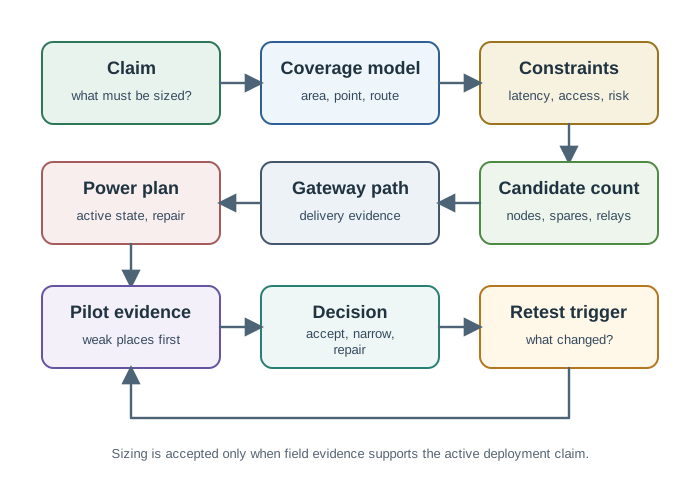
The route is a loop. Pilot evidence can send the design back to spacing, gateway placement, enclosure choice, duty cycle, or maintenance planning. That is normal. The mistake is treating the first estimate as the final deployment promise.
16.7 Inputs That Change the Size
Different WSN deployments are sized by different constraints. A count that is adequate for one claim may be wasteful or unsafe for another.
Coverage model Area coverage is driven by region size and weak locations. Point coverage is driven by target inventory. Barrier and path coverage are driven by crossings, route bends, gates, and bypasses.
Redundancy Backup sensing, spare nodes, independent relay paths, and repair access can require more devices than a single-coverage drawing suggests.
Connectivity Gateway reach, relay density, interference, walls, foliage, antenna placement, and backhaul availability can become the binding constraint.
Power and service Battery size, sleep schedule, access difficulty, charging path, replacement interval, and maintenance crew capacity can change the accepted deployment size.
Installation limits Mounting height, enclosure rating, cable access, safety rules, tenant access, calibration time, and commissioning windows often decide whether a sizing plan is practical.
Validation plan The first estimate should reserve effort for pilot checks, weak-location tests, ground-truth comparison, failed-node response, and post-install retesting.
The safest sizing habit is to identify the binding constraint. If coverage suggests one count but gateway reach, battery service, or installation access requires a different plan, the final size must satisfy the harder constraint or narrow the claim.
16.8 From Coverage to Candidate Count
Candidate count is an estimate that needs validation. The method depends on the coverage type.
Area deployments Start with the monitored boundary and a conservative sensing model. Then inspect edges, corners, obstructions, mounting locations, environmental variation, and the active duty-cycle state.
Point deployments Start with the target inventory. Count each valve, tank, bearing, door, shelf, or asset that needs sensing. Add redundancy only where consequence or repair access justifies it.
Barrier and path deployments Start with the boundary or route. Check likely crossings, gates, turns, blind spots, timing requirements, and whether the claim is crossing detection or continuous observation.
Hybrid deployments Split the site into separate claims. A chemical room, fence line, tank list, and service corridor should not be collapsed into one vague “site coverage” count.
Avoid false precision. A spreadsheet can estimate a starting count, but field evidence decides whether the selected spacing, mounting position, and active state support the claim.
16.9 Gateway and Backhaul Sizing
Gateway sizing is not only a capacity question. It is also a reachability, failure, and operations question.
Reachability Can weak sensors reach a gateway or relay path in the accepted operating state?
Load Does the gateway plan handle normal reporting, bursts, retries, firmware updates, and diagnostics without hiding lost data?
Failure mode What happens when a gateway, relay, backhaul link, or power source fails? Is the claim narrowed or is there a repair path?
Backhaul The path from gateway to platform or local system needs its own evidence: coverage, uptime, data cap, security, and support owner.
A deployment can have enough sensors and still fail if readings cannot leave the site. Sizing should therefore record both sensing capacity and data-delivery capacity.
16.10 Power, Maintenance, and Spares
Power sizing should be tied to the monitoring claim. A long sleep interval can reduce service work, but it may also create unacceptable blind time or slow event delivery.
Power review: State the duty-cycle rule, wake trigger, expected event timing, battery or power source, service interval, and evidence from measured current or field trials.
Maintenance review: State who can reach each device, how failed devices are detected, how many spares are stocked, and how quickly a weak claim is repaired.
Limit: Do not reuse a power plan from slow environmental logging for safety alarms, intrusion response, or fast control without a new latency and consequence review.
The accepted size should include support capacity. If the operations team cannot replace batteries, clean enclosures, recalibrate sensors, or respond to failed-node alerts, the nominal deployment size is not honest.
16.11 Deployment-Energy Sizing Controls
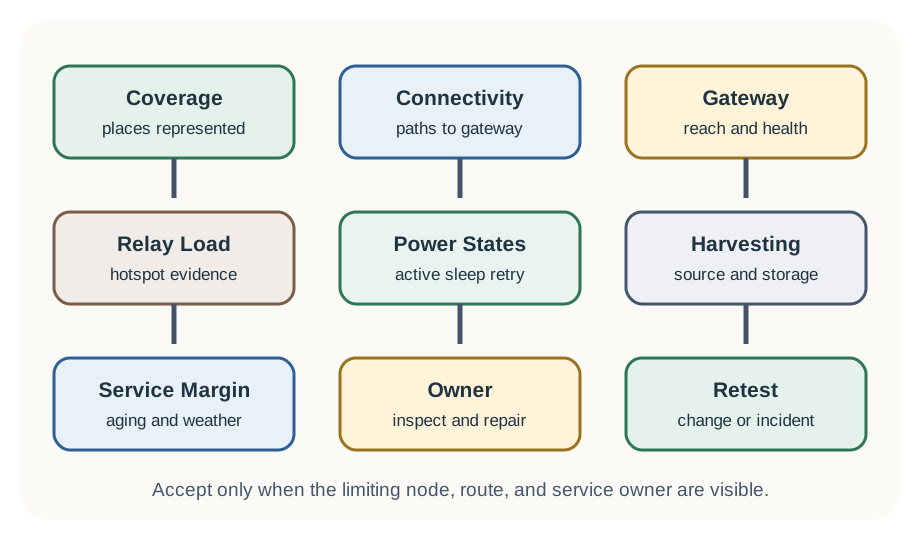
The merged deployment-energy chapter adds a practical check: sizing is not only a coverage count. The final size must include the power, relay, gateway, and service controls that keep the accepted claim alive.
Use Figure 16.2 as a guardrail for the energy side of sizing.
Review:
- coverage evidence and connectivity evidence separately; a sensed event is not useful if it cannot reach a gateway or local decision point
- actual installed locations, known gaps, boundary assumptions, rejected zones, and weak-location pilot checks
- gateway reach, upstream behavior, local buffering, restart behavior, clock handling, and health reporting
- relay hotspots, including receive, forward, retry, route repair, and early-depletion risk
- power states for active work, sleep work, retry work, maintenance work, update windows, and failure recovery
- harvesting or battery-service evidence, including low-harvest periods, storage aging, deep-discharge recovery, and inspection ownership
Do not accept a deployment plan that averages energy across all nodes while ignoring the limiting relay or gateway-adjacent node. The limiting node often determines the service claim.
16.12 Limiting Node and Service Margin
Many-to-one WSN traffic makes average sizing dangerous. A node near the sink may relay traffic for many other nodes, while an edge node sends only its own readings. If every node receives the same battery and the estimate uses average energy, the near-sink group can die first and disconnect the network while the spreadsheet still looks healthy.
| Limiting case | Sizing response | Proof before acceptance |
|---|---|---|
| Near-sink relay hotspot | Add relays, larger batteries, denser nodes near the sink, aggregation, or another sink | Forwarding-load trace, retry count, battery-current evidence, and route-repair behavior |
| Gateway shadow or weak wall | Add an alternate relay, move the gateway, narrow the claim, or change the backhaul plan | Link-margin check, missed-reading test, gateway health record, and failure-mode response |
| Hard-to-service sensor | Increase service margin, improve access, add spares, or narrow the service interval | Maintenance route, owner, replacement time, spare stock, and stale-data rule |
| High-consequence point target | Add redundant sensing or a stronger fault response only for that target | Consequence record, redundancy evidence, alert latency, and repair ownership |
Extra margin should name the failure mode it covers. A spare for a high-consequence valve, an alternate relay for a gateway shadow, a larger cell for a hot relay group, and a shorter maintenance interval for drift are different decisions. Each one needs an owner and retest trigger, otherwise it becomes an unowned promise.

Phoebe’s Why
An “average energy” spreadsheet quietly assumes every node draws the same current, but a relay’s current is not its own traffic – it is its own traffic plus everyone downstream of it. A nameplate mAh figure has to survive the same internal-resistance sag and self-discharge derating on every node, so two identical cells with two different duty cycles do not reach empty at the same time; they reach the same derated charge floor at very different rates. That is the whole near-sink hotspot in one sentence: not a topology abstraction, but current accounting against a shared, shrinking budget.
The Derivation
The same mAh-to-Wh chain used throughout this book applies to every node before traffic is even considered:
\[V_{term} = V_{oc} - I\,R_{int}, \qquad E_{usable}(\mathrm{Wh}) \approx Q_{usable}(\mathrm{Ah})\times V, \qquad Q_{usable}=f_{derate}\times Q_{nominal}\]
A relay carrying its own reading plus \(n\) downstream nodes’ forwarded traffic draws roughly:
\[I_{relay} \approx I_{edge}\times(1+n)\]
Free-space path loss sets how far one hop can reach before the next relay tier is needed, and that range scales with the band’s frequency:
\[\Delta\mathrm{FSPL} = 20\log_{10}\frac{f_2}{f_1}\]
Worked Numbers: Edge Node Versus Relay
The chapter names no battery or radio, so take a standard/typical WSN cell (3.6 V, 2000 mAh, \(R_{int}=3\ \Omega\)) derated 80% to \(Q_{usable}=1600\) mAh, and a standard/typical edge-node average current \(I_{edge}=50\ \mu\)A:
- Edge-node life: \(1600/0.050 = 32{,}000\) h \(= 3.65\) years
- A relay carrying traffic for \(n=5\) downstream nodes (representative, since the chapter fixes no topology): \(I_{relay}=50\times(1+5)=300\ \mu\)A
- Relay life on the identical battery: \(1600/0.300 = 5{,}333\) h \(= 0.609\) years \(\approx7.3\) months
The same derated 1600 mAh budget lasts 3.65 years at the edge and about 7.3 months at the relay – the spreadsheet-healthy average hides a node dying in under a year. Band choice compounds this: dropping from 2.4 GHz to 868 MHz buys about \(20\log_{10}(2400/868)=8.83\) dB more link margin, or roughly \(10^{8.83/20}=2.76\times\) the usable hop range for the same power, which lets a design reach the same footprint with fewer relay tiers and a smaller \(n\) stacking onto the innermost hotspot.
16.13 Knowledge Check: Limiting Node
16.14 Budget Without False Precision
Budget sizing should separate the estimate from the evidence. Hardware unit price is only one line. The size can be dominated by installation labor, enclosures, gateways, power, backhaul, spare stock, calibration, permits, site access, and validation.
Include Sensor nodes, mounting hardware, enclosures, gateways, backhaul, power, spares, installation, commissioning, field validation, monitoring, repair visits, and documentation.
Do not overclaim Do not present sample prices, battery life, vendor ranges, or gateway ratios as universal facts. Treat them as inputs that must be replaced by local quotes and pilot evidence.
Keep options visible Record why a cheaper device was rejected or why a more expensive device reduced installation, maintenance, or validation risk.
The best sizing record makes tradeoffs reviewable. It does not hide them inside a single total cost.
16.15 Pilot Evidence Record
Use Figure 30.3 to capture the result of a sizing review. The record should stay short enough to update after a pilot or failed validation test.
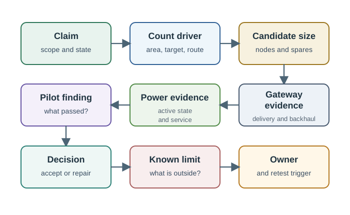
A pilot should test the weakest parts of the estimate first: edge locations, hard-to-reach targets, link margins, battery draw, enclosure behavior, installation time, data delivery, and maintenance workflow.
16.16 Worked Review: Greenhouse Expansion
A greenhouse team wants to extend temperature and humidity monitoring into a new growing bay. The requirement is area coverage during the night schedule, with enough evidence to detect weak zones near doors and fans.
Claim: The new growing bay will have area monitoring during the normal night schedule, with weak zones near doors and fans explicitly tested.
Count driver: Region boundary, sensor mounting options, airflow variation, obstruction from shelves, and the accepted active state.
Gateway driver: Reachability from the far bay corner and from sensors behind humid equipment.
Power driver: Sleep schedule, sampling interval, service access, enclosure moisture, and battery replacement workflow.
Decision: Start with a pilot count that covers representative weak locations, then finalize only after field readings and gateway-path tests match the claim.
Retest trigger: Reopen sizing after shelf movement, fan changes, gateway relocation, sensor model change, repeated missed readings, or changed night schedule.
The point is not to memorize a node count. The point is to show how a candidate count becomes acceptable only after weak-location evidence and operating-state evidence support it.
16.17 Worked Review: Pipeline Valve Monitoring
A utility needs to monitor named valves along a pipeline corridor. The requirement is point coverage at the valves, not full area monitoring of the corridor between valves.
Claim: The named valve list has point coverage with a reporting path to the gateway during the accepted schedule.
Count driver: Valve inventory, criticality, redundancy needs, calibration access, and whether each target has an acceptable mounting point.
Gateway driver: Long route geometry, terrain, relay options, backhaul availability, and weak links during bad weather or maintenance states.
Decision: Size the target list and gateway path separately. Do not buy area coverage for empty corridor space unless a new area or path claim is added.
Retest trigger: Reopen sizing after valve additions, route change, gateway movement, repeated link loss, failed calibration, or changed repair-response target.
Point deployments often look smaller than area deployments, but they can still be constrained by communication path, service access, and critical-target redundancy.
16.18 Common Sizing Mistakes
One number for the whole site Hybrid sites need separate counts and evidence for rooms, targets, boundaries, and routes.
Counting installed instead of active nodes Sleeping, failed, uncalibrated, unreachable, or disabled nodes should not silently satisfy the accepted size.
Forgetting gateways The sensor count is not enough if weak nodes cannot deliver data or if one gateway failure invalidates the claim.
Using unit price as the decision Cheap hardware can become expensive through installation time, battery visits, false alarms, missed readings, and support overhead.
No pilot margin Sizing that has no room for pilot findings, weak locations, spares, and repair work usually shifts cost into operations.
No retest trigger Deployment size drifts after layout changes, sensor replacement, gateway movement, firmware changes, and environmental change.
16.19 Review Checklist
Before accepting a deployment size, check:
- Is the monitoring objective written as a testable claim?
- Is the count driver area, point, barrier, path, or hybrid?
- Which redundancy level is required, and why?
- Which sensors count in the accepted active state?
- Did the sizing include gateway reach and data delivery?
- Did the sizing include power, service, spares, and maintenance ownership?
- Were weak locations tested before final approval?
- Does the budget include installation, validation, and repair effort?
- Does the record state known limits?
- What exact change reopens sizing?
16.20 Knowledge Check: Binding Constraint
16.21 Knowledge Check: Budget Evidence
16.22 Matching: Sizing Inputs
16.23 Ordering: Deployment Sizing Review
16.24 Summary
WSN deployment sizing is the discipline of turning a monitoring objective into a supportable field plan. The accepted size should include the count driver, active state, gateway path, power plan, service model, budget evidence, pilot results, known limits, owner, and retest trigger.
Do not let a calculator, sample price list, or clean coverage drawing become the whole decision. Use estimates to start the review, then approve only what pilot evidence and operations evidence can support.
16.25 Key Takeaway
WSN Deployment Sizing should connect WSN design choices to measurable deployment evidence, operational constraints, and retest triggers.
16.26 Concept Relationships
- WSN Coverage Fundamentals explains how sizing depends on coverage claims and evidence.
- WSN Coverage: Problem Types separates area, point, barrier, path, hybrid, and redundancy decisions.
- WSN Energy Duty Cycling explains how sleep schedules affect active sizing and latency.
- WSN Energy Management covers broader WSN power tradeoffs.
- Communication Paradigms connects gateway and reporting-path evidence to the deployment size.
16.27 What’s Next
Previous: Duty Cycle Worked Examples
Next: WSN Labs
Use Duty Cycle Worked Examples to review active-state evidence before accepting a sizing record. Continue to WSN Labs to practice deployment planning, gateway checks, and field validation.