48 Link Quality and Route Repair
WSN routing link quality, ETX routing, wireless sensor network link estimation, WSN route trace, WSN packet delivery evidence, WSN routing repair
48.1 Start With the Field Story
A short route is not always a good route. Link-quality review starts with delivery evidence, reverse acknowledgments, sample age, traffic type, and repair behavior so hop count does not hide an unreliable path.
48.2 In 60 Seconds
WSN link quality routing is not just “choose the strongest signal” or “choose the shortest path.” A reviewer needs evidence that the selected path actually supports the monitoring claim: packet delivery, reverse acknowledgment behavior, retries, parent changes, route-state age, relay pressure, freshness, missing-data visibility, and repair behavior.
This chapter reviews link quality as a routing evidence process. ETX, MIN-T, WMEWMA, RSSI, LQI, and packet reception ratios are useful vocabulary, but the review question is broader: what did the route observe, what did it ignore, what assumptions made the metric meaningful, and what deployment change would force retesting?

Phoebe’s Why
In truly empty space, power spreads out over an ever-larger sphere as it travels, so the density any receiver sees falls as the inverse square of distance – that is the whole physical content behind free-space path loss. Real WSN deployments are not empty space: walls, furniture, bodies, and shelving scatter and absorb energy on top of the pure geometric spreading, so loss grows faster than \(1/d^2\). The log-distance model keeps the same inverse-power shape but lets the exponent grow past 2 to soak up that extra environmental loss, which is exactly why a route that looked fine in an open hallway test can lose margin once it is measured through the intended walls.
The Derivation
Isotropic spreading of transmit power \(P_t\) over a sphere of radius \(d\):
\[S = \frac{P_t}{4\pi d^2}\]
Combined with receive aperture \(A_e=\lambda^2/4\pi\), this gives the Friis free-space path loss:
\[\mathrm{FSPL} = \left(\frac{4\pi d}{\lambda}\right)^2\]
The log-distance model generalizes free space (where \(n=2\)) to real environments with path-loss exponent \(n\):
\[PL(d)_{dB} = PL(d_0)_{dB} + 10n\log_{10}\left(\frac{d}{d_0}\right) + X_\sigma\]
Link margin above receiver sensitivity \(P_{rx,min}\):
\[M = P_t + G_t + G_r - PL(d) - P_{rx,min}\]
Worked Numbers: A 2.4 GHz WSN Hop
- Reference loss at \(d_0=1\) m, 2.4 GHz: \(\lambda=c/f=0.125\) m, \(\mathrm{FSPL}(1\,\mathrm{m})=20\log_{10}(4\pi/0.125)=40.0\) dB.
- Free-space extrapolation to 50 m (\(n=2\)): \(PL=40.0+20\log_{10}(50)=74.0\) dB.
- Log-distance with catalog-typical indoor/obstructed \(n=3.0\): \(PL=40.0+30\log_{10}(50)=91.0\) dB – 17.0 dB more than the free-space number, purely from the distance/obstacle exponent the brief asks about.
- Fade margin: catalog-typical WSN radio \(P_t=0\) dBm, near-unity antenna gains, receiver sensitivity \(-95\) dBm. Received power at 50 m through the \(n=3\) path is \(0-91.0=-91.0\) dBm, so margin \(=-91.0-(-95.0)=4.0\) dB – thin enough that a route review should flag it for repair or a shorter hop rather than trust a one-time RSSI reading.
48.3 Learning Objectives
By the end of this chapter, you will be able to:
- explain why hop count and signal strength alone are weak routing evidence in WSNs
- distinguish delivery evidence, reverse acknowledgment evidence, signal indicators, and route-state evidence
- use ETX, MIN-T, WMEWMA, RSSI, LQI, and probe results as bounded review inputs
- review link-quality route traces for stale state, relay pressure, repair behavior, and missing-data visibility
- build a link-quality routing evidence record with accepted limits, owner, fallback action, and retest trigger
48.4 WSN Link Quality Review
48.5 Prerequisites
This chapter builds on WSN Routing Fundamentals Review, WSN Routing Introduction Review, WSN Routing Challenge Review, WSN Routing Protocol Classification Review, WSN Routing Data Aggregation Review, and WSN Routing Labs and Exercises Review.
If a learner cannot describe source nodes, relay nodes, sinks, parent or next-hop state, acknowledgments, retries, freshness, and route repair, review those chapters before using link-quality metrics.
48.6 Link Quality Review Scope
Link quality review starts with the application decision, not with a metric formula.
Monitoring claim State what the WSN must support: trend, alarm, event query, command delivery, inventory, coverage, or maintenance status.
Delivery evidence Record whether packets, summaries, or query responses arrive with the freshness and completeness the decision requires.
Reverse evidence Check whether acknowledgments, replies, probes, or route-control traffic can travel back reliably enough to avoid false repairs.
Route state Record parent, next hop, gradient, rank, neighbor table, expiry, probe age, and repair timer assumptions.
Relay pressure Identify nodes that carry repeated forwarding work near sinks, gateways, bridges, corridors, or aggregation roles.
Operations loop Name owner, monitoring signals, fallback action, accepted limits, and retest trigger.
48.7 Evidence Map
Use Figure 48.1 to keep signal measurements tied to route evidence.
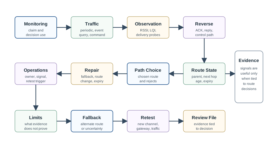
The map prevents a common mistake: treating one measurement as the whole routing decision. RSSI can be useful, but it is not delivery evidence by itself. A path trace can be useful, but it is stale if probes, acknowledgments, and failure behavior are not reviewed.
48.8 Measurement Proof Limits
RSSI Signal strength can indicate whether a received packet arrived strongly or weakly. It does not prove future delivery, reverse-link quality, or route freshness by itself.
LQI and radio indicators Hardware indicators can help detect link health, but their meaning depends on radio, firmware, channel, and environment.
Packet reception evidence Probe or data delivery history is closer to routing reality, but it needs age, sample scope, traffic type, and failure context.
ETX or MIN-T Expected-transmission style metrics help compare links and paths when forward and reverse delivery evidence is current and representative.
WMEWMA-style estimation Blending recent delivery evidence with longer-term smoothing can reduce noise, but the window, decay, and expiry rules must be visible.
Route trace The trace shows what the protocol chose. It must be reviewed with missing-data, freshness, relay-pressure, and repair evidence.
48.9 Evidence Record
Use Figure 48.2 to turn link-quality observations into a reviewable routing decision.
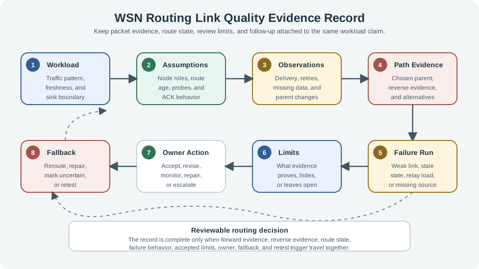
Workload: State traffic pattern, urgency, freshness, completeness, and sink boundary.
Assumptions: Record node roles, radio channel, route-state age, probe behavior, and whether acknowledgments matter.
Observations: Record delivery evidence, reverse evidence, retries, parent changes, route repairs, missing data, and relay pressure.
Decision: Accept, revise, or reject the route choice; record rejected alternatives and accepted limits.
Operations: Name owner, monitoring signal, fallback action, and retest trigger.
48.10 Reviewing Hop Count Against Link Quality
Hop count is a topology clue, not a routing acceptance test. A path with fewer hops can be worse when a link is lossy, asymmetric, stale, overloaded, or hard to repair. A path with more hops can be better when each hop has current delivery evidence, reverse evidence, and repair visibility.
Use this review question: Does the chosen path reduce route risk for this workload, or did the metric simply hide the risky link inside a shorter route?
Use Figure 48.3 to keep the path comparison concrete.
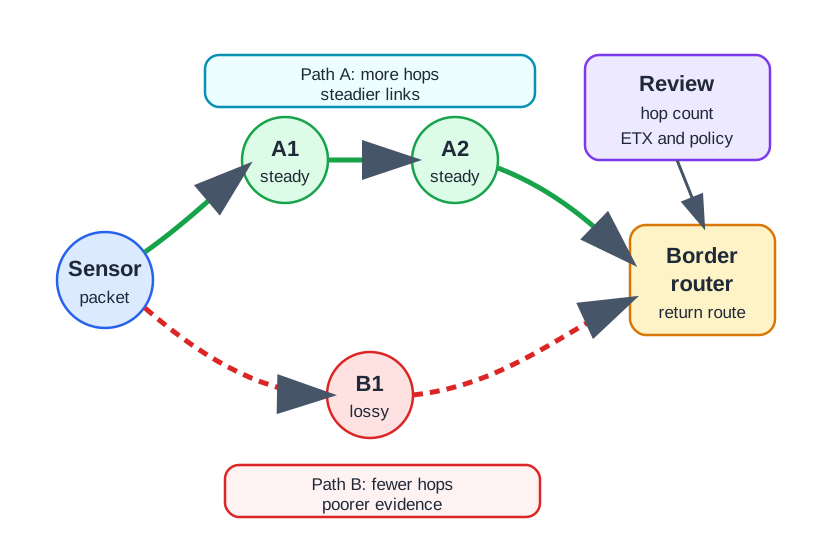
Read the figure as a review pattern: Path A is not accepted because it has more hops, and Path B is not rejected merely because it has fewer hops. The decision turns on whether each hop has current delivery evidence, whether the return direction supports acknowledgments or replies, and whether the route can repair without hiding missing data.
Acceptable evidence: The trace shows why the chosen parent or next hop is better for the workload, including retry behavior and current probe age.
Weak evidence: The trace names a shorter route but does not show delivery, reverse acknowledgment, or repair behavior.
Retest trigger: New interference, moved gateway, channel change, firmware change, traffic change, or repeated parent changes.
48.11 Reverse Links and ACKs
Many routing decisions fail because the forward path looks healthy while the reverse path is weak. If acknowledgments, route replies, control messages, or downlink commands matter, the review must include reverse evidence.
Forward evidence: Did data or probe packets arrive at the next hop or sink?
Reverse evidence: Did acknowledgments, route replies, or control responses return reliably enough to avoid false retransmission or false repair?
Failure clue: Frequent retransmission with apparently good forward delivery can indicate reverse-link weakness or stale state.
Decision output: Revise if the path cannot show both directions needed by the workload and routing protocol.
48.12 Reviewing Estimation Windows
Link estimation needs a memory of recent behavior, but stale memory can keep bad links in service. The review should make estimator behavior visible without overfitting to one fixed parameter.
Recent evidence Does the estimate respond when recent packets fail, route replies stop, or parent changes accelerate?
Longer-term stability Does the estimate avoid route churn when a short disturbance clears and the route remains acceptable?
Expiry How old can link evidence become before the route must probe, expire, repair, or escalate?
Traffic match Are probes representative of the actual data size, timing, direction, and channel conditions?
Hysteresis Does the route avoid switching back and forth when candidates are close or evidence is noisy?
Operations signal Which log, counter, or alert tells the owner that link estimates are stale or unstable?
Use a link-evidence ledger when the route compares candidate parents or next hops. The ledger should be one row per candidate transition, not one row for the whole route, so the reviewer can see where the risk lives: a marginal child-to-parent hop, a stressed relay near the sink, an old neighbor-table entry, or a reverse-link problem that appears only during acknowledgment or query traffic.
| Ledger field | What to record | What weak evidence hides |
|---|---|---|
| Sample scope | Probe or data traffic, packet size, direction, channel, and measurement age. | A link that looked healthy only during setup. |
| Forward evidence | Delivered packets, retries, missing sources, and whether probes match the workload. | RSSI that is strong while delivery is unstable. |
| Reverse evidence | Acknowledgments, replies, downlink commands, or route-control responses. | A path that receives data but cannot confirm, repair, or answer. |
| Estimator rule | ETX or similar score, smoothing window, expiry, and hysteresis threshold. | Old evidence that keeps a failing parent selected. |
| Repair observation | Parent changes, blacklisted links, retries during repair, and fallback route. | A route that looks accepted but has no tested recovery behavior. |
When both directions matter, a simplified ETX review often starts from 1 / (forward delivery * reverse delivery) and sums link costs across the path. That number is useful only if the ledger says what was measured, how old the evidence is, and which direction the workload or protocol actually depends on. Do not mix a probe PRR, an application delivery ratio, hardware LQI, and route-control reply rate unless the estimator window, decay, expiry, and hysteresis rule are visible.
Low-power radio coverage also has a transitional region where links work intermittently. A route estimator should keep those links out of a simple good/bad bucket and move them through visible repair states.
| Repair state | Evidence that moves the link | Review question |
|---|---|---|
| Healthy | Fresh forward and required reverse evidence stay within accepted limits. | Is the sample representative of the actual workload? |
| Suspect | Retries rise, acknowledgments become inconsistent, or parent churn begins. | Does hysteresis prevent noise from causing route flapping? |
| Repairing | The node probes or chooses another parent from a current neighbor table. | Are missing packets and duplicate effects visible during repair? |
| Quarantined | The link is avoided until fresh evidence proves it has recovered. | What prevents immediate reuse of the same marginal link? |
| Retesting | A deployment change or incident invalidates old route evidence. | Who owns the retest and fallback decision? |
Local repair is acceptable only when the repair state is observable. If the node silently switches parent while the application loses sources or freshness, the routing layer has hidden the failure instead of repairing the decision path. During repair, the application-level effect still matters: aggregated traffic can hide which source was lost, duplicate packets can inflate an event count, and an alternate parent can move relay pressure to a node that was already close to its duty-cycle or energy limit.
48.13 Worked Review: Building Sensor Route
Scenario: Room sensors report regular environmental readings to a building gateway. Trend visibility and missing-room detection matter more than immediate control.
Workload: Regular source-to-gateway readings with missing-room visibility and maintenance review.
Evidence: Parent changes, retry evidence, probe age, acknowledgments, missing-source evidence, and relay pressure near the gateway.
Decision: Accept a link-quality route only if it distinguishes quiet rooms from failed links and exposes repeated relay stress.
Retest trigger: Gateway relocation, channel change, new obstruction, firmware change, or repeated parent churn.
48.14 Worked Review: Event Query Route
Scenario: A gateway occasionally asks whether a region crossed a condition. The response must show which sources matched, which were missing, and whether results were fresh.
Workload: Event or query traffic with freshness, matching-source, and missing-region visibility.
Evidence: Interest or query scope, source matching, response freshness, duplicate handling, reverse replies, and route expiry.
Decision: Revise if link quality looks acceptable for probes but late responses, missing sources, or stale route state change the decision.
Fallback: Rerun query through an alternate route, widen the evidence window, or mark the region as uncertain until retested.
48.15 Common Mistakes
Signal strength as proof RSSI or a hardware indicator can support review, but it does not replace delivery, reverse, freshness, and repair evidence.
Forward-only review Ignoring acknowledgments or route replies can make a weak reverse path look like a healthy forward path.
Stale estimates Old probe history can keep a failing route alive after topology, traffic, channel, or interference changes.
Metric-only decision An ETX or MIN-T score is not deployment acceptance unless assumptions, sample age, repair behavior, and limits are recorded.
Ignoring relay pressure A reliable link can still be a poor route if it pushes too much forwarding work onto a stressed relay.
No retest trigger Link quality is environmental. The record should say what change invalidates the route evidence.
48.16 Review Checklist
Before accepting link-quality routing evidence, verify that the record includes:
- monitoring claim, traffic pattern, freshness need, and sink boundary
- chosen route, rejected alternatives, route-state age, and route repair rule
- forward delivery evidence, reverse acknowledgment evidence, retries, and parent changes
- probe or data sample scope, estimator window, expiry rule, and hysteresis behavior
- relay pressure, missing-data visibility, aggregation effect, and exception path
- accepted limits, owner, fallback action, monitoring signal, and retest trigger
48.17 Knowledge Check: Link Quality Evidence
48.18 Knowledge Check: Reverse Link Risk
48.19 Knowledge Check: Repair Evidence
48.20 Match Link Evidence to Review Meaning
48.21 Order a Link Quality Route Review
48.22 Summary
WSN routing link quality is a review discipline, not a single number. Strong review connects signal indicators, delivery evidence, reverse acknowledgments, route-state age, relay pressure, freshness, repair behavior, and operations ownership. Metrics such as ETX, MIN-T, and WMEWMA are useful only when their assumptions and limits are visible.
48.23 Key Takeaway
WSN Routing Link Quality Review should balance path reliability, link quality, energy cost, latency, aggregation, topology change, control overhead, and deployment evidence.
48.24 Concept Relationships
Routing challenges Explains why weak links, stale state, relay pressure, and repair cost make hop count insufficient.
Protocol classification Uses link evidence to compare tree, reactive, geographic, quality-aware, and data-centric family assumptions.
Data aggregation Requires link evidence that summaries preserve source coverage, freshness, missing-member visibility, and exception paths.
Routing labs Turns link-quality review into repeatable lab runbooks, failure exercises, and evidence records.
48.25 What’s Next
Continue with WSN Routing: Trickle Algorithm to review dissemination and repair behavior, then revisit WSN Routing Labs and Exercises Review, WSN Routing Data Aggregation Review, and WSN Routing Protocol Classification Review when a route choice needs stronger evidence.