Chapters

12 Zigbee Protocol Stack

zigbee-thread
zigbee
protocol-stack

A wall switch sends an On command and receives a radio acknowledgement, yet the lamp stays dark. The local frame arrived, but the application may have rejected the endpoint or cluster. The stack becomes useful when each layer explains a different part of that outcome.

12.1 Start With the Mesh Job

Follow One Lamp Command Through the Layers

Picture a wall switch sending one command to a lamp. The lamp may be joined to the mesh yet still ignore the command. A useful review keeps radio delivery, route choice, service delivery, and the meaning of “turn on” as separate claims.

A protocol means agreed rules for exchanging messages. IEEE 802.15.4 is the local radio and frame foundation used here. Zigbee is a system built above it for forming the network, routing, discovery, and application behavior. A gateway is a device that joins the local mesh to another service path. Name the switch, lamp, route, command, reply, and owner at each boundary.

Block one link, use the wrong endpoint, remove a binding, restart the lamp, and repeat the command. Check the frame record, route record, service record, and final lamp state. A radio reply alone must not be reported as completed action.

This walk-through does not cover every role or profile. The deeper sections map layers, addressing, binding, groups, security, discovery, and application meaning onto the same evidence chain.

Start with the job a Zigbee mesh has to do in Zigbee Protocol Stack: let constrained devices discover, join, route, report, and recover with enough evidence for a reviewer to trust the result.

Follow one device from network formation to ordinary traffic before comparing options. Roles, profiles, clusters, bindings, security, and operational mistakes are easier to judge when each one changes that device story.

Overview: What the Zigbee Stack Separates

Zigbee stack review asks whether a communication claim is assigned to the right layer. IEEE 802.15.4 PHY and MAC evidence explains the local radio link and frame exchange. Zigbee network evidence explains joining, addressing, path behavior, and network security custody. APS evidence explains endpoints, binding, groups, and service delivery. ZDO and ZCL evidence explain discovery, clusters, commands, attributes, and application meaning.

The stack is useful only when it prevents overclaiming. A joined device is not automatically a working application. A listed cluster is not automatically the correct behavior. A gateway-visible device is not automatically a complete Zigbee evidence record.

The layer names are part of the evidence record. IEEE 802.15.4 owns the PHY and MAC layers. Zigbee adds the network layer for formation, addressing, routing, and network security. Above that, the Application Support Sublayer (APS) carries service delivery for endpoints, binding, and groups. The application layer contains the application framework, the Zigbee Device Object (ZDO) for device and service discovery, and ZCL or profile-specific application behavior. A stack diagram is useful only when each layer's owner and proof are named.
12.2 Stack and Superframe Walkthroughs

Inspect Figure 12.1 to follow one lamp command and demand distinct evidence at each layer boundary.

Zigbee stack for an On Off command with endpoint and key custody, network route repair, 802.15.4 MAC frame and optional ACK, PHY channel and RSSI evidence.
Figure 12.1: Zigbee stack with application, APS and ZDO, network, MAC, and PHY jobs beside a five-item evidence rail.

Read Figure 12.1 from APPLICATION · ZCL, which owns the On/Off meaning, to 802.15.4 MAC, which owns contention, sequencing, and optional acknowledgement. The EVIDENCE rail keeps command, route, and frame proof distinct.

Then inspect Figure 12.2 to place contention, reservation, and sleep on the actual 16-slot timeline.

Beacon superframe with slots zero through fifteen, CAP slotted CSMA CA, CFP with at most seven GTS allocations, and an inactive sleep period before the next beacon.
Figure 12.2: Beacon-enabled IEEE 802.15.4 superframe with sixteen slots, CAP, CFP, GTS limit, and inactive period.

Read CAP · slotted CSMA/CA and CFP · ≤ 7 GTS in Figure 12.2 against the numbered slots. INACTIVE PERIOD shows where sleep is possible, while the closing note prevents sixteen slots from being mistaken for sixteen guaranteed users.

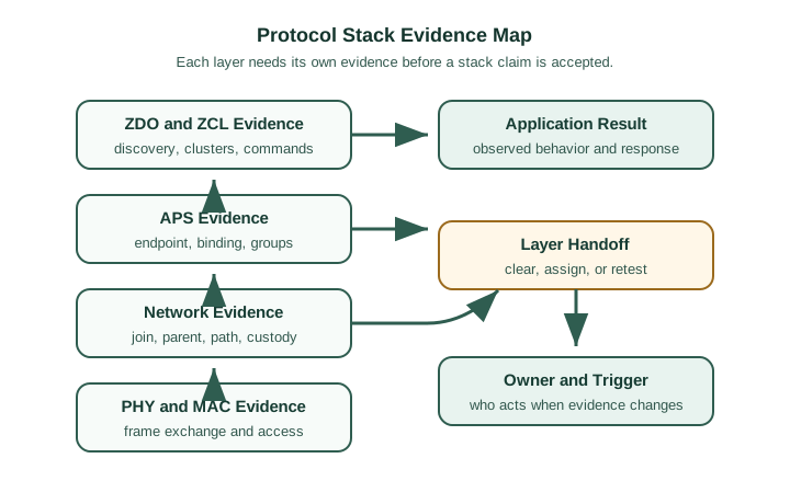
Before overview: What the Zigbee Stack Separates, inspect Figure 12.3 to compare “ZDO and ZCL Evidence” with “PHY and MAC Evidence”. Their juxtaposition makes A protocol-stack claim is ready only when each layer has its own evidence and the handoff to the next owner is explicit visible.

Zigbee protocol stack evidence map linking PHY and MAC evidence, network evidence, APS evidence, ZDO and ZCL evidence, application result, layer handoff, owner, and retest trigger.
Figure 12.3: A protocol-stack claim is ready only when each layer has its own evidence and the handoff to the next owner is explicit.

Read Figure 12.3 from “ZDO and ZCL Evidence” to “PHY and MAC Evidence”. Taken together, “ZDO and ZCL Evidence” and “PHY and MAC Evidence” express A protocol-stack claim is ready only when each layer has its own evidence and the handoff to the next owner is explicit. For overview: What the Zigbee Stack Separates, the observed relationship between “ZDO and ZCL Evidence” and “PHY and MAC Evidence” is evidence that “ZDO and ZCL Evidence” carries into the next decision.

If you only need the intuition, this layer is enough: approve only the layer behavior that was observed, record where the next handoff begins, and write the retest trigger before treating the protocol-stack claim as ready.

Core Layer Responsibilities

PHY and MAC

Link evidence covers channel conditions, frame exchange, acknowledgements, retries, link quality, and local radio symptoms.

Network layer

Network evidence covers join state, coordinator or Trust Center custody, addresses, parent choice, route behavior, and rejoin boundaries.

APS, ZDO, and ZCL

Application evidence covers endpoints, binding, groups, discovery, clusters, attributes, commands, reports, and response behavior.

Operations

Operations evidence names the owner, logs, gateway mapping, firmware boundary, support workflow, known gaps, and retest trigger.

Beginner Examples

  • A device can join the Zigbee network while the intended command still fails at an endpoint, binding, group, or cluster boundary.
  • A route can recover while the application still displays stale state through a gateway or controller rule.
  • A cluster name can appear in discovery while the command direction, attribute value, reporting rule, or response handling is still unproven.

Overview Knowledge Check

Practitioner: Build the Stack Evidence Record

A practical stack record starts from the symptom or approval claim. It then names the deployment boundary, records just enough lower-layer evidence to support or clear each layer, and avoids using one successful observation as proof for unrelated behaviors.

The record should be specific enough that support can tell what changed. Firmware, coordinator replacement, gateway update, binding change, route movement, endpoint revision, cluster behavior, and application mapping can all invalidate different parts of the stack evidence.

Layer
Review Question
Evidence To Record
Common Overclaim
PHY and MAC
Can the device exchange link frames under the reviewed conditions?
Channel, placement, link-quality observations, acknowledgements, retries, interference notes, and enclosure or antenna boundary.
"The radio worked once, so every command path is approved."
Network
Is the device joined to the intended Zigbee network and using a supportable path?
Coordinator or Trust Center custody, join state, parent, route, address scope, rejoin behavior, and path-change evidence.
"The inventory has a device name, so routing and recovery are proven."
APS
Did delivery reach the intended endpoint or service boundary?
Endpoint identifiers, binding table, group membership, profile boundary, APS delivery evidence, and service owner.
"Network delivery means the application target was correct."
ZDO and ZCL
Does discovery and cluster behavior match the product claim?
Node descriptor, active endpoint, simple descriptor, cluster, attribute, command direction, report, and response evidence.
"A cluster name in the gateway proves the command behavior."
Operations
Who can maintain and retest the stack claim?
Firmware boundary, gateway mapping, logs, replacement path, security custody, owner, known gaps, and retest trigger.
"The protocol label is enough for future support."

Worked Review: Reachable Device, Missing Behavior

A device joins successfully, reports presence, and appears in a coordinator inventory. A controller command still does not change the expected device behavior. The review should preserve the lower-layer proof but move the active question upward: endpoint target, binding, group path, cluster command, command direction, response handling, and gateway mapping.

The safest decision is narrow. Network reachability can be accepted for the tested boundary, while the command behavior remains unapproved until APS and ZCL evidence match the claim.

Worked Review: Gateway Upgrade Changes Meaning

After a gateway update, a device still joins and reports presence, but one application behavior changes. That is a retest trigger for the stack handoff between Zigbee behavior and controller interpretation. Compare discovery, endpoint, binding, group, cluster, command, attribute, and gateway mapping evidence before and after the update.

Practitioner Knowledge Check

Under the Hood: Handoffs, Owners, and Retest Triggers

Most stack failures happen at a handoff. Link evidence becomes network evidence only after joining and path behavior are proven. Network evidence becomes application evidence only after endpoint and service delivery are proven. Application evidence becomes product evidence only after cluster behavior, gateway interpretation, and operations ownership are recorded.

This separation keeps a diagnosis from jumping to the wrong fix. Replacing an antenna will not repair a wrong endpoint. Changing a binding table will not fix a weak installed path. Updating a gateway can invalidate a controller mapping even when native Zigbee traffic is healthy.

Handoff
What It Proves
What It Does Not Prove
Retest Trigger
PHY/MAC to NWK
The device can exchange frames and move into Zigbee network behavior under tested conditions.
Route recovery, endpoint delivery, command meaning, or gateway interpretation.
Channel, antenna, enclosure, placement, interference, router position, or firmware change.
NWK to APS
The joined device can use a supportable network path toward a service endpoint.
Correct binding, group membership, ZCL command direction, or controller rule behavior.
Parent change, route change, coordinator replacement, permit-join change, binding change, or group change.
APS to ZDO/ZCL
The endpoint, discovery, cluster, command, attribute, report, and response evidence match the reviewed behavior.
That every gateway, app, automation, or future firmware will preserve the same meaning.
Endpoint revision, cluster behavior change, attribute reporting change, firmware update, or command mapping change.
Zigbee to operations
The protocol behavior has a named owner, diagnostic record, known scope, and supportable retest path.
That untested device types, rooms, bridges, controller apps, or future ownership changes inherit the approval.
Gateway update, bridge replacement, app rule change, security custody change, or support-owner change.

Diagnosis Pattern

  1. Preserve the symptom. Record what failed, the device state, current parent or route evidence, endpoint target, gateway path, and recent changes.
  2. Clear only the necessary lower layer. If command meaning is wrong, preserve join and path evidence, then inspect APS and ZCL before blaming RF.
  3. Change one boundary at a time. Mixing channel, firmware, binding, gateway, and application changes destroys the evidence trail.
  4. Write the unsupported claim. If only reachability was proven, say command behavior is still outside approval. If only native Zigbee was proven, say bridge behavior still needs evidence.

Under-the-Hood Knowledge Check

12.3 IEEE 802.15.4 DSSS and Beacon-Superframe Mechanics

At 2.4 GHz, the IEEE 802.15.4 PHY maps each four-bit data symbol to a 32-chip direct-sequence pattern and transmits chips using O-QPSK. The chip rate is 2 Mchip/s, so

Rs=2 Mchip/s32 chip/symbol=62.5 ksymbol/s,R_s=\frac{2\ \text{Mchip/s}}{32\ \text{chip/symbol}}=62.5\ \text{ksymbol/s},

and four bits per symbol gives

Rb=4Rs=250 kbit/s.R_b=4R_s=250\ \text{kbit/s}.

The receiver correlates the noisy received chips against the permitted 32-chip patterns and chooses the best-matching symbol. Spreading does not make interference disappear; it gives the detector processing structure and resilience to limited chip errors. Channel occupancy, adjacent Wi-Fi energy, receiver saturation, antenna placement, and hidden nodes still affect packet delivery.

12.3.1 Unslotted CSMA/CA, Step by Step

For non-beacon operation, a device initializes the number of backoffs NB=0 and backoff exponent BE=macMinBE. It then follows this loop:

  1. Choose a random integer from 00 through 2BE12^{BE}-1 and wait that many backoff periods.
  2. Perform clear-channel assessment.
  3. If the channel is idle, transmit the frame.
  4. If it is busy, increment NB, increase BE up to macMaxBE, and fail with channel-access failure if NB exceeds macMaxCSMABackoffs; otherwise repeat.

This random delay reduces repeated collisions among devices that became ready together. It cannot detect a hidden transmitter that the sender cannot hear. Beacon-enabled slotted CSMA/CA aligns the process to superframe backoff boundaries and uses a contention-window check before transmission; do not apply unslotted timing numbers to a beacon capture.

An acknowledgement is optional per data frame. When the ACK-request bit is set, the sender waits for the short MAC ACK and may retry if it does not arrive. Channel-access backoffs and frame retries are different counters: a clear channel followed by a lost frame is not a CCA failure. Logs should preserve CCA failures, transmissions, missing ACKs, and retry exhaustion separately.

12.3.2 Build the 16-Slot Superframe

In beacon-enabled mode, the coordinator bounds the beacon interval and active superframe duration with beacon order BOBO and superframe order SOSO:

BI=aBaseSuperframeDuration2BO,SD=aBaseSuperframeDuration2SO,0SOBO14.BI=aBaseSuperframeDuration\,2^{BO}, \qquad SD=aBaseSuperframeDuration\,2^{SO}, \qquad 0\le SO\le BO\le14.

The active superframe contains 16 equal slots. The beacon starts the active period. A contention access period (CAP) follows, where devices use slotted CSMA/CA. An optional contention-free period (CFP) follows the CAP and contains Guaranteed Time Slots allocated by the PAN coordinator; at most seven GTS descriptors may be allocated. If SO<BOSO<BO, an inactive interval follows, allowing sleepy devices and the coordinator—if its application permits—to reduce power.

For the 2.4 GHz PHY, the base duration is 960 symbols, or 15.36 ms, and a base slot is 60 symbols, or 0.96 ms. With BO=6BO=6 and SO=3SO=3:

BI=15.36×26=983.04 ms,BI=15.36\times2^6=983.04\ \text{ms}, SD=15.36×23=122.88 ms,SDBI=2SOBO=12.5%.SD=15.36\times2^3=122.88\ \text{ms}, \qquad \frac{SD}{BI}=2^{SO-BO}=12.5\%.

Each active slot is SD/16=7.68SD/16=7.68 ms in this example. A GTS gives reserved superframe capacity, not zero latency: a packet may wait for its allocated slot, and loss can still require recovery. The CAP must also retain enough room for management and contention traffic. Validate beacon acquisition, clock drift, missed-beacon policy, CAP load, GTS allocation, ACK behavior, and sleep current before claiming deterministic or low-power operation.

12.4 Separate a Clear Channel from a Completed Lamp Command

Follow Figure 12.1 from application meaning through APS and network routing to MAC and PHY. The application owns the On/Off command and the intended lamp endpoint. The network supplies the route. The MAC frame and optional acknowledgement establish a narrower local exchange, while PHY observations describe channel and signal conditions. A valid frame does not prove the correct endpoint acted.

For a timing calculation, use the chapter’s beacon-enabled example with beacon order 6 and superframe order 3. The beacon interval is 983.04 ms and the active period is 122.88 ms. The inactive period is 983.04 − 122.88 = 860.16 ms. Sixteen equal active slots therefore last 122.88 divided by 16 = 7.68 ms each. These timings apply to the stated superframe configuration, not every Zigbee network.

Read Figure 12.2 from beacon through CAP and any CFP allocation into the inactive period. The numbered slots divide time; they do not promise a separate guaranteed allocation for every possible user. A command becoming ready during inactivity may wait for an opportunity, and reservation still cannot remove radio loss or application checks.

Predict what a clear-channel assessment establishes. It indicates the sender’s local channel observation at that moment, not that a hidden transmitter is absent at the receiver. Next, receive an acknowledgement but direct the command to an unsupported endpoint. The application result should remain rejected or unconfirmed rather than being promoted to completed by the radio trace.

Repeat the test after route repair and after a lamp restart. Retain source and destination endpoints, command identity, route evidence, frame result and final lamp state. Separating channel-access backoffs from missing-acknowledgement retries helps identify which stage is under pressure.

This module’s layered review prevents a mesh join or good signal level from standing in for useful lighting control. The numerical superframe explains one timing boundary; the application response and observed state explain whether the requested action crossed the rest of the stack successfully.

12.5 Summary

  • Zigbee protocol-stack review starts with a bounded layer claim, not with a stack diagram or protocol label.
  • PHY and MAC evidence proves only the tested link behavior; it does not prove network, endpoint, cluster, gateway, or product behavior.
  • Network evidence should record joining, coordinator or Trust Center custody, addresses, parent or route behavior, and rejoin boundaries.
  • APS, ZDO, and ZCL evidence should record endpoint, binding, group, discovery, cluster, command, attribute, report, and response behavior.
  • Operations evidence names the owner, diagnostic record, known gaps, support workflow, and retest trigger for future changes.
Key Takeaway

Approve a Zigbee protocol-stack claim only when each layer handoff has enough evidence for the reviewed behavior and the unsupported claims remain explicit.

12.6 See Also

Zigbee Fundamentals and Architecture

Review the broader architecture boundaries across IEEE 802.15.4, Zigbee roles, application behavior, and operations.

Zigbee Network Formation

Connect join control, coordinator custody, parent selection, and network formation evidence to stack readiness.

Zigbee Network Topologies

Review coordinator, router, end-device, parent, and route-diversity evidence for topology claims.

Zigbee Application Profiles

Extend the APS and ZCL evidence trail into endpoint, profile, cluster, binding, and gateway behavior.