27 IEEE 802.15.4 Fundamentals
IEEE 802.15.4 fundamentals, 802.15.4 PHY MAC, 802.15.4 device roles, 802.15.4 frame budget, low-rate wireless personal area network
27.1 Start With the Wireless Story
Start with a low-power radio frame trying to cross a short link. IEEE 802.15.4 sets the PHY and MAC ground rules, but the design still has to prove channel choice, roles, frame budget, security, and coexistence before higher stacks can work.
27.2 In 60 Seconds
IEEE 802.15.4 defines the lower wireless layers for low-rate wireless personal area networks. It gives constrained devices a way to share a radio channel, exchange short MAC frames, identify a PAN, acknowledge local transmissions, and support low-power operation. It does not define a full product ecosystem, a complete application model, or an end-to-end mesh protocol by itself.
Use this chapter to understand the fundamentals that every 802.15.4-based design must review:
- the PHY/MAC boundary
- device capability and product roles
- star, peer, tree, and mesh assumptions
- the 127-byte MAC frame limit
- channel access and beacon assumptions
- security and upper-layer overhead
- coexistence and installed-link evidence

Phoebe’s Why
This chapter names three legal homes for an 802.15.4 radio – 2.4 GHz, 915 MHz, and 868 MHz – and mostly treats the choice as a channel-count and rate question. Underneath, it is the same \(c=f\lambda\) trade this module derives for Wi-Fi and cellular bands, just applied to a different PHY family. Moving down in frequency lengthens the wavelength, which both grows the antenna and buys back path-loss margin – but 802.15.4’s legacy sub-GHz PHYs also spend some of that margin back on data rate, because their direct-sequence spreading trades fewer chips per bit for a slower symbol rate. The channel-plan numbers this chapter already gives for 2.4 GHz let that whole trade be checked with real arithmetic instead of a slogan about “sub-GHz reaches farther.”
The Derivation
\[\lambda=\frac{c}{f} \qquad \Delta\mathrm{FSPL}=20\log_{10}\frac{f_2}{f_1}\]
For a direct-sequence spread PHY, the chip rate sets a fixed spreading factor over the data rate, and that ratio sets the processing gain this chapter already uses for the 2.4 GHz PHY:
\[\text{spreading factor}=\frac{R_{chip}}{R_{bit}} \qquad G_{proc}(\mathrm{dB})=10\log_{10}\!\left(\frac{R_{chip}}{R_{bit}}\right)\]
Worked Numbers: 2.4 GHz Versus This Standard’s Own Sub-GHz PHYs
- Wavelengths: \(\lambda_{2.45\text{GHz}}=3.00\times10^{8}/2.45\times10^{9}=0.122\) m; \(\lambda_{915\text{MHz}}=0.328\) m; \(\lambda_{868\text{MHz}}=0.345\) m – both sub-GHz antennas run roughly \(2.7\times\) longer than the 2.4 GHz chip antenna this chapter already assumes.
- Same-distance path-loss reward: \(\Delta\mathrm{FSPL}(868\to2450\text{MHz})=20\log_{10}(2450/868)=9.01\) dB; \(\Delta\mathrm{FSPL}(915\to2450\text{MHz})=8.55\) dB – roughly an order of magnitude in received power favoring the sub-GHz bands at equal range.
- Legacy sub-GHz PHY cost (IEEE 802.15.4-2006 BPSK modes): 868 MHz runs 300 kchip/s at 20 kbit/s (15.0 chips/bit, \(250/20=12.5\times\) slower than this chapter’s 2.4 GHz rate); 915 MHz runs 600 kchip/s at 40 kbit/s (also 15.0 chips/bit, \(250/40=6.25\times\) slower).
- Processing gain paid for that spreading: \(10\log_{10}(15.0)=11.8\) dB at 868/915 MHz versus the \(10\log_{10}(8.0)=9.03\) dB this chapter already derives for 2.4 GHz – the sub-GHz legacy PHYs buy back almost 3 dB more receiver robustness on top of the 8.5-9.0 dB free-space reward, but only by sending roughly a sixth to a twelfth of the bits per second. A design that needs both range and 250 kbit/s throughput cannot get it from a band choice alone.
27.3 Learning Objectives
By the end of this chapter, you will be able to:
- explain what IEEE 802.15.4 defines and what it leaves to upper layers
- separate FFD, RFD, coordinator, router, parent, child, and end-device role language
- identify why the 127-byte MAC frame limit shapes payload and protocol overhead decisions
- compare non-beacon channel access with beacon-enabled scheduling assumptions
- explain why coexistence and installed-link evidence are part of fundamentals, not late deployment details
- review an 802.15.4 design claim without repeating unsupported range, battery-life, or interoperability claims
27.4 Core Boundary
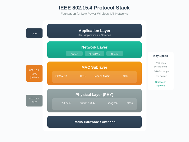
Use Figure 27.1 whenever a design says it uses 802.15.4. The standard supplies radio and MAC behavior, but the complete system depends on what runs above those layers.
27.5 What 802.15.4 Defines
The PHY layer covers how the radio sends and receives symbols in the selected band and channel. It includes the radio behavior needed to transmit and receive packets, but the exact product performance depends on the radio, antenna, firmware, power settings, enclosure, and environment.
The MAC layer covers local link behavior:
- frame structure
- PAN identification
- short and extended addressing support
- association and disassociation support
- CSMA/CA channel access
- optional acknowledgments and retries
- beacon-enabled operation where configured
- optional MAC security services
These functions make 802.15.4 a useful foundation for constrained wireless systems. They do not by themselves prove routing, application interoperability, user onboarding, cloud connection, or product support behavior.
27.6 What Upper Layers Add
Upper layers add the behavior learners often associate with a finished IoT network:
- routing and route repair
- IPv6 adaptation and compression
- application data models
- commissioning and trust establishment
- gateway or border-router behavior
- firmware-update workflow
- diagnostics and product support records
That is why Zigbee, Thread, 6LoWPAN, WirelessHART, and other 802.15.4-based systems can share lower-layer ideas while remaining different systems. Same radio foundation does not mean same network behavior.
27.7 Folded Stack Boundary Evidence
Same radio does not mean same protocol. Two devices may agree on 802.15.4 PHY and MAC behavior while disagreeing on routing, IPv6 adaptation, application data model, commissioning flow, security material, gateway behavior, diagnostics, or firmware-update practice.
Before accepting an “802.15.4 compatible” claim, record the layer boundary:
- which behavior is provided by the PHY or MAC;
- which upper-layer stack supplies routing, addressing, commissioning, and application meaning;
- which device role is lower-layer capability and which is product or stack configuration;
- whether frame budget, security overhead, retry behavior, and field evidence support the claimed payload or reliability;
- what change reopens review, such as product firmware, channel plan, gateway, device role, or application model.
27.8 Device Capability And Product Role
802.15.4 uses device capability terms, while upper-layer stacks and products use role terms. Keep them separate.
An FFD can implement the full function set needed for coordination or routing roles. An RFD is a simpler device that normally communicates through an FFD and avoids forwarding traffic for others.
A product role may be coordinator, router, parent, child, sleepy end device, border router, bridge, actuator, sensor, or gateway. Some of those roles are created by the upper-layer stack, not by the lower-layer standard alone.
Review questions:
- Does the design say which devices must keep receivers available?
- Does it separate leaf-node behavior from forwarding behavior?
- Does it explain how sleepy devices receive downlink data?
- Does it identify the coordinator, parent, router, gateway, or border device?
- Does it distinguish hardware capability from configured product role?
27.9 Topology Fundamentals
An 802.15.4-based system may be arranged as a simple star, a peer relationship, a tree-like hierarchy, or a mesh depending on the upper-layer stack and product configuration.
Do not treat topology as a radio-only property. A radio may support frame exchange, but routing behavior depends on the stack above the MAC and on the installed configuration.
Review questions:
- Which device starts or manages the PAN?
- Which devices are allowed to forward traffic?
- Is multi-hop behavior actually configured, or only assumed?
- What happens when a parent, router, or coordinator is unavailable?
- How is replacement, rejoin, or reset recorded?
27.10 Frame Budget
The maximum MAC frame size is 127 bytes. That small budget is one of the most important 802.15.4 fundamentals. Every header, address, security field, adaptation header, and application field competes for space.
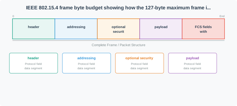
Use Figure 27.2 to review payload claims. A design should identify which addressing mode, security setting, and upper-layer headers are present before it claims how much application data fits efficiently.
Frame-budget review prompts:
- Is the claim using the MAC frame limit, an upper-layer packet size, or an application payload size?
- Which addressing fields are present?
- Is MAC security enabled, and what fields does it add?
- Does the upper-layer stack add adaptation, fragmentation, routing, or application headers?
- Is the application payload small enough to avoid unnecessary fragmentation?
- Does the design measure retransmissions and actual delivery behavior, not just theoretical size?
27.11 Channel Access
In non-beacon operation, devices use CSMA/CA behavior to reduce collisions before transmitting. This works well for many low-duty-cycle systems, but it is not a guarantee that every device can transmit at any time without contention.
In beacon-enabled operation, a coordinator can define a superframe structure. This can support synchronized activity and optional contention-free periods, but it adds timing and coordination assumptions that must be verified.
Review questions:
- Is the traffic periodic, event-driven, bursty, or mixed?
- Does the device need immediate transmission, scheduled transmission, or long sleep periods?
- Are acknowledgments and retries enabled where reliability requires them?
- Does the design record failed attempts, backoff behavior, and retry counts?
- Is a beacon or GTS claim supported by actual configuration evidence?
27.12 Security Overhead
802.15.4 includes MAC security services, but security is not only a checkbox. Security fields consume part of the frame budget, and the complete product also needs key management, commissioning, identity handling, update policy, and recovery procedures.
Review questions:
- Which layer provides encryption, authentication, and replay protection?
- Which fields are added to the MAC frame?
- How are keys established, rotated, replaced, and retired?
- What happens after a device reset or replacement?
- Which security behavior belongs to the upper-layer stack or product system?
27.13 Coexistence
Many 802.15.4 deployments share spectrum with Wi-Fi, Bluetooth, other 802.15.4 networks, and local interference sources. Coexistence is a fundamentals topic because channel choice and retry behavior can change the design outcome before a product is deployed at scale.
Review questions:
- Which channels are actually used at the installation?
- What other radios are active nearby?
- Are packet loss, retries, association failures, or latency spikes recorded?
- Was the channel plan based on observation or only on a diagram?
- Does the design include a retest process after site changes?
27.14 Design Review Flow
Use this order when reviewing an 802.15.4 fundamentals claim:
- State the claim exactly.
- Identify which layer is responsible.
- Name the upper-layer stack if the claim goes beyond PHY/MAC behavior.
- Check device capability and configured product role.
- Check frame budget and overhead.
- Check channel access and reliability evidence.
- Check coexistence and installed-link evidence.
- Record which assumptions remain unproven.
27.15 Worked Review: Building Sensor
A building sensor design says it uses 802.15.4 and will send small occupancy events to a central system.
A clean fundamentals review would not stop at the radio statement. It would ask which upper-layer stack is used, whether each sensor is a sleepy end device, which device acts as parent or coordinator, how downlink data reaches the sensor, how much application payload remains after headers and security, which channel was selected, and what installed evidence proves events are delivered reliably.
The acceptable result is not a slogan such as “802.15.4 is low power.” The acceptable result is a short record that names the stack, roles, frame assumptions, channel observations, retry behavior, and unresolved risks.
27.16 Worked Review: Retrofitted Lighting
A lighting retrofit says every wall switch and luminaire can forward messages. That may be true for some product configurations, but it is not proven by 802.15.4 alone.
The review should separate radio capability from routing role. It should identify which devices are powered continuously, which devices are allowed to route, whether sleepy devices exist, how route repair works, whether coexistence was measured in the installed space, and which acceptance record proves the final topology works after installation.
27.17 Common Mistakes
Avoid these mistakes when learning or reviewing 802.15.4:
- treating 802.15.4 as a complete application protocol
- assuming same radio chip means same network compatibility
- calling every multi-hop design a mesh without naming the routing layer
- accepting battery-life claims without duty-cycle and retry evidence
- using theoretical data rate as application throughput
- ignoring header and security overhead in the frame budget
- treating channel planning as a one-time paper exercise
- assigning forwarding roles to devices that need to sleep most of the time
- accepting deployment success without installed-link evidence
27.18 Knowledge Check
27.19 Match The Fundamental To The Review Evidence
27.20 Order The Fundamentals Review
27.21 The 802.15.4 Physical Layer Sets the Radio Budget
IEEE 802.15.4 specifies the PHY and MAC for low-rate, low-power wireless personal-area networks. It is the radio foundation under Zigbee, Thread, and 6LoWPAN — not a complete networking stack on its own. The PHY answers three questions: which frequencies the radio uses, how bits become radio symbols, and how large one frame may be.
Three license-exempt bands are defined: the worldwide 2.4 GHz ISM band, the 902–928 MHz band (the Americas), and the 868 MHz band (Europe). The 2.4 GHz PHY dominates deployments. It offers 16 channels numbered 11–26, spaced 5 MHz apart, each carrying 250 kbit/s using O-QPSK with direct-sequence spread spectrum (DSSS).
A single 802.15.4 frame (the PSDU) is at most 127 bytes. That deliberately small ceiling — chosen for low power and low latency — shapes everything above it: 16- or 64-bit addressing, an optional security header, and the payload must all fit inside those 127 bytes.
The standard family has several amendment names that appear in product literature. 802.15.4a added alternate PHY work such as UWB support, 802.15.4c and 802.15.4d addressed regional bands, 802.15.4e added MAC enhancements used by industrial stacks, 802.15.4f addressed active RFID, and 802.15.4g targeted smart utility and neighbourhood networks. A review should not treat the number alone as a deployment proof; it should name the actual PHY, channel plan, MAC mode, and upper-layer stack in use.
Range claims need the same caution. Teaching summaries often quote ordinary indoor links in the tens of metres, with much longer outdoor line-of-sight results possible under clean radio conditions. The engineering record should verify installed RSSI, LQI, retry count, antenna orientation, duty cycle, and interference instead of assuming that one range number applies to every enclosure and site.
Boundary example. If a product brief says “twenty sensors will form a self-healing mesh,” the 802.15.4 part of the claim only proves local radio frames, PAN identifiers, channel access, and optional ACKs. The review still has to name the routing stack, identify which powered nodes forward, define how sleepy leaves receive downlink traffic, and show what happens when a parent disappears.
The same boundary applies to payload size. A 60-byte sensor report may fit easily in the 127-byte MAC frame when short addressing and minimal headers are used. Add security fields, an adaptation header, routing metadata, and an application envelope, and the usable payload can shrink enough that fragmentation or redesign is required. Fundamentals review prevents that mistake before deployment testing begins. 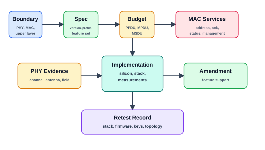
If you only need the intuition: 802.15.4 at 2.4 GHz is 16 channels, 250 kbit/s raw, and a 127-byte frame. Almost every design trade-off in Zigbee and Thread flows from those three numbers.
27.21.1 Overview Knowledge Check
27.22 Read the Channel Plan and the Real Throughput
Channel centre frequencies at 2.4 GHz follow a simple rule: Fc = 2405 + 5 × (k − 11) MHz for channel k in 11–26. So channel 11 sits at 2405 MHz and channel 26 at 2480 MHz. Each channel occupies roughly 2 MHz of its 5 MHz slot, leaving guard space between neighbours.
The 250 kbit/s label is not delivered throughput. Every frame also carries a MAC header, addressing, an optional security header, and a 2-byte FCS, and the MAC spends time on inter-frame spacing, CSMA/CA backoff, and the acknowledgment.
Worked example. Send one full 127-byte frame at 2.4 GHz. The PSDU is 127 × 8 = 1016 bits, so its air time is 1016 / 250000 ≈ 4.06 ms. Add the PHY preamble + SFD + PHR (6 bytes ≈ 0.19 ms), a receiver turnaround, a short inter-frame space, and an 11-byte acknowledgment (≈ 0.35 ms), and one reliable exchange takes well over 4.5 ms. Because that overhead is fixed per frame, delivered goodput is a fraction of 250 kbit/s — and smaller payloads make the fraction worse, since the per-frame overhead is amortised over fewer data bytes.
Use the channel formula as a quick sanity check during coexistence review. Channel 20 is 2405 + 5 × 9 = 2450 MHz, channel 25 is 2475 MHz, and channel 26 is 2480 MHz. A report that simply says “we used a high channel” is incomplete; it should record the exact channel, nearby Wi-Fi channel widths, retry counters, and whether all devices actually support that channel in the configured region.
| Quantity | Value at 2.4 GHz | Why it matters |
|---|---|---|
| Channels | 16 (numbered 11–26) | Room to pick a quiet channel away from Wi-Fi |
| Channel spacing | 5 MHz | Neighbours do not overlap; a 20 MHz Wi-Fi channel covers ~4 of them |
| Raw rate | 250 kbit/s | A 127-byte frame is ~4.1 ms of air time |
| Max PSDU | 127 bytes | Forces header discipline (6LoWPAN compression, short addresses) |
27.22.1 Practitioner Knowledge Check
27.23 O-QPSK, DSSS, and Why 250 kbit/s Is Robust
At 2.4 GHz the PHY groups every 4 data bits into one symbol (16 possible symbols) at a symbol rate of 62.5 ksymbol/s — that is the 250 kbit/s. Each symbol is then mapped to a 32-chip near-orthogonal pseudo-random sequence and transmitted at 2 Mchip/s using offset-QPSK with half-sine pulse shaping (equivalent to MSK). So 32 chips × 62.5 ksymbol/s = 2 Mchip/s.
That 32-chips-per-4-bits spreading is what makes the link tough. The DSSS processing gain is 10 log₁₀(2 Mchip/s ÷ 250 kbit/s) = 10 log₁₀(8) ≈ 9 dB. The receiver correlates against the known chip sequences, so it can recover weak symbols and reject some narrowband interference. This is why the standard can require a receiver sensitivity of −85 dBm, while many products exceed that, even though a typical transmitter may emit only 0 dBm (1 mW).
Worked example. A node transmitting at 0 dBm into a receiver rated −97 dBm can tolerate about 97 dB of path loss before the link fails — comfortably tens of metres indoors. Notice what fixes or breaks the link: antenna quality, channel cleanliness, and obstacles, not the data rate. Raising throughput is not an 802.15.4 lever; choosing a clean channel and protecting the link budget is.
Processing gain is not a substitute for deployment evidence. If a link has 18 dB of margin during a quiet desk test, a metal cabinet, body shadowing, or a new 2.4 GHz transmitter can consume much of that margin. Fundamentals review should therefore pair the PHY explanation with installed RSSI, LQI, retry, and channel-energy evidence instead of treating DSSS as a blanket guarantee.
The frame budget has the same hidden-layer effect. A payload that fits in one unsecured short-address frame may require extra fields once security, adaptation, and routing are enabled. If that pushes an application message into fragmentation, a single lost fragment can force more retransmission work than the raw PHY rate suggests.
27.23.1 Under-the-Hood Knowledge Check
27.24 Summary
IEEE 802.15.4 fundamentals are about boundaries and evidence. The standard defines low-power PHY/MAC behavior, but complete IoT behavior depends on the stack and product above it. A strong review separates radio claims from routing and application claims, checks device roles, accounts for the 127-byte frame budget, verifies channel access assumptions, and treats coexistence and installed-link evidence as part of the fundamentals.
27.25 Key Takeaway
IEEE 802.15.4 Fundamentals should connect 802.15.4 frame structure, addressing, topology, MAC behavior, power use, security, coexistence, and deployment evidence before selecting the stack.
27.26 Concept Relationships
- PHY/MAC boundary relates to protocol selection because Zigbee, Thread, 6LoWPAN, and other systems add different behavior above 802.15.4.
- Device capability relates to power behavior because a forwarding device and a sleepy leaf device have different receiver, memory, and maintenance requirements.
- Frame budget relates to application design because every required header reduces the room available for useful payload.
- Channel access relates to reliability evidence because contention, acknowledgments, retries, and beacon assumptions determine observed delivery behavior.
- Coexistence relates to deployment acceptance because radio behavior must be verified in the actual installed environment.
27.27 What’s Next
- 802.15.4 Fundamentals Series Guide for the reading route through the series.
- 802.15.4 Overview for a concise orientation.
- 802.15.4 Overview and Protocol Stack for stack-boundary review.
- 802.15.4 Operation for association, polling, acknowledgments, retries, sleep, and operation records.
- 802.15.4 Features and Specifications for PHY/MAC choices, frame budget, and security overhead.
- 802.15.4 Coexistence for channel and interference evidence.
- 802.15.4 Deployment for installed-system acceptance records.