30 802.15.4 Coexistence
802.15.4 coexistence, IEEE 802.15.4 Wi-Fi interference, 802.15.4 channel planning, 802.15.4 interference review, 2.4 GHz coexistence
30.1 Start With the Wireless Story
Coexistence starts when two radios share the same room and the same 2.4 GHz air. The review story is to spot symptoms, map Wi-Fi and 802.15.4 channels, choose mitigations, validate them, and write down when the site must be retested.
30.2 In 60 Seconds
802.15.4 coexistence is a measurement problem. Wi-Fi, Bluetooth, microwave ovens, neighboring 802.15.4 PANs, and other local transmitters can all affect packet delivery, latency, retries, and battery use. A good coexistence review does not rely on a universal channel rule. It observes the local RF environment, chooses candidates that the devices and region support, tests under realistic traffic, and records when to retest.
Use this chapter to review:
- symptoms that suggest interference rather than path loss or software failure
- how Wi-Fi channel width and traffic timing can affect 802.15.4 links
- how RSSI, LQI, packet loss, retries, and latency should be interpreted together
- how to choose and validate candidate channels
- how to decide between channel change, Wi-Fi coordination, traffic shaping, topology change, or a different PHY option
- how to document coexistence decisions so they can be revisited after the RF environment changes

Phoebe’s Why
Every symptom, channel map, and CCA mode on this page is about surviving inside one crowded 2.4 GHz band. But 802.15.4 is not defined only at 2.4 GHz – the same standard also specifies 868 MHz and 915 MHz sub-GHz PHYs, and this chapter’s own Common Mistakes list warns against “assuming sub-GHz is automatically better without checking region, antenna, hardware, and application data needs.” The wavelength equation explains exactly what that trade is. Wi-Fi does not exist in the 868/915 MHz bands at all, so a sub-GHz 802.15.4 link has no channel map to draw against Wi-Fi 1/6/11 – there is nothing to avoid. What it gives up instead is antenna size and, because free-space loss falls with frequency, some of the path-loss margin that a smaller 2.4 GHz antenna quietly buys back.
The Derivation
Every 802.15.4 PHY obeys the same speed lock between frequency and wavelength:
\[\lambda = \frac{c}{f}, \qquad \ell_{\lambda/4} = \frac{\lambda}{4}\]
Comparing free-space loss between any two 802.15.4 bands at the same distance, the distance term cancels:
\[\Delta\mathrm{FSPL} = 20\log_{10}\frac{f_2}{f_1}\]
Diffraction is not a separate rule: a wave bends around an obstacle efficiently only while the obstacle is comparable to or smaller than \(\lambda\). A longer \(\lambda\) therefore diffracts around and penetrates more of an ordinary room’s furniture and framing than a shorter one, for the same reason a lower band is described elsewhere as reaching “farther” indoors.
Worked Numbers: 802.15.4’s Three PHY Bands
- Wavelength and antenna size: at 868 MHz, \(\lambda=3.00\times10^8/8.68\times10^8=34.6\) cm, quarter-wave \(\approx8.64\) cm; at 915 MHz, \(\lambda=32.8\) cm, quarter-wave \(\approx8.20\) cm; at this chapter’s own 2450 MHz nominal channel-11-26 band, \(\lambda=12.2\) cm, quarter-wave \(\approx3.06\) cm – roughly a 2.7x smaller antenna at 2.4 GHz, the same packaging pressure this module’s other chapters describe for Wi-Fi and cellular bands.
- Path-loss delta, 915 MHz to 2450 MHz: \(20\log_{10}(2450/915)=8.55\) dB, a linear power ratio of \((2450/915)^2=7.17\times\) – so at the same distance and antenna gain, the 2.4 GHz PHY this chapter’s channel map lives on starts every link with about 8.55 dB less margin than the sub-GHz option it is being compared against in the Common Mistakes warning.
- Sanity check against this chapter’s own dB reasoning: the Overview section already establishes that 802.15.4’s roughly 1 mW against Wi-Fi’s roughly 100 mW-1 W is a 20-30 dB power disadvantage. An 8.55 dB frequency penalty for staying at 2.4 GHz is real, but it is about a third of that power gap – consistent with this chapter’s own conclusion that channel choice and CCA, not raw power, are what make 2.4 GHz workable at all.
- Why the escape route is not free: moving to 868/915 MHz removes every Wi-Fi-overlap symptom this page diagnoses – there is no channel 1/6/11 to map against – but it also drops the data rate 802.15.4 offers at 2.4 GHz and requires the roughly 2.7x larger antenna above, plus a completely different regional-band review. That is precisely the “checking region, antenna, hardware, and application data needs” this chapter’s Common Mistakes bullet already demands before treating sub-GHz as an automatic win.
30.3 Learning Objectives
By the end of this chapter, you will be able to:
- distinguish coexistence symptoms from weak-link, routing, and application problems
- explain why nearby Wi-Fi traffic can disrupt 2.4 GHz 802.15.4 networks
- choose channel candidates from measured local evidence rather than generic rules
- identify when traffic shaping or topology changes are better than a channel change
- review battery and latency claims without relying on fixed retry multipliers
- create a coexistence record with metrics, mitigation, fallback, and retest trigger
30.4 Coexistence Diagnosis Flow
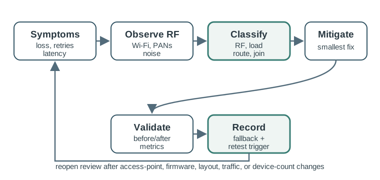
Use Figure 30.1 when a network starts failing after a nearby wireless change. The first task is to classify the failure. Packet loss can come from interference, weak signal, hidden nodes, routing changes, overloaded parents, bad firmware, or application bursts.
30.5 Coexistence Symptoms
Interference is likely when several of these appear together:
- packet loss rises while device placement has not changed
- LQI or packet success drops even though RSSI still looks acceptable
- retries increase during certain hours or after a nearby network change
- latency becomes variable rather than consistently high
- battery devices spend more time awake because of retries, listening, or failed joins
- failures correlate with Wi-Fi usage, access-point changes, maintenance windows, or new equipment
- some locations fail only when doors, people, vehicles, or equipment change the RF path
Do not diagnose from one metric. RSSI can look strong when the desired signal and interference are both strong. LQI, packet error rate, retry count, latency, and event timing are usually more useful together.
30.6 What To Observe
Before changing channels, collect evidence:
- active Wi-Fi channels and channel widths
- nearby 802.15.4 PANs and their channels
- channel occupancy during quiet and busy periods
- packet loss and retry counts by device group
- latency distribution for user-visible actions
- join and rejoin failures
- link quality by location, not just by device type
- firmware, coordinator, router, and access-point changes near the failure time
The observation window should match the real problem. A hospital, classroom, warehouse, office, or apartment building may look quiet at night and crowded during the day.
30.7 Channel Candidate Review
Some 2.4 GHz 802.15.4 channels are often better candidates around common Wi-Fi channel plans, but the best choice is still local. Channel width, transmit power, physical distance, access-point placement, neighboring networks, and device support all matter.
Review prompts:
- Which channels are allowed by the device, firmware, product stack, and deployment region?
- Which Wi-Fi channels and widths are active during the failure window?
- Which 802.15.4 candidate channels avoid direct overlap and strong adjacent-channel energy?
- Does the coordinator and every device support the candidate channel?
- Does a channel change require rejoining, recommissioning, downtime, or user action?
- What fallback channel is available if the candidate performs poorly?
30.8 Mitigation Options
Choose the smallest mitigation that matches the evidence.
Channel change can help when:
- one Wi-Fi channel or neighboring PAN overlaps the current 802.15.4 channel
- candidate channels are supported by all devices
- a maintenance window can handle rejoin or recommissioning risk
- the failure is tied to RF conditions rather than application overload
Wi-Fi coordination can help when:
- the same team controls Wi-Fi access points
- changing Wi-Fi channel width or placement reduces overlap
- 802.15.4 devices cannot be moved or reconfigured easily
Traffic shaping can help when:
- synchronized reports create contention even on a clean channel
- adding jitter or staggering reports reduces retry bursts
- the network load is the problem, not external interference
Topology change can help when:
- only devices behind one parent or router fail
- a coordinator or router is overloaded
- path loss and interference vary strongly by location
Different PHY or product choice can help when:
- the 2.4 GHz band is persistently unsuitable
- regional rules and hardware support another band
- the application can tolerate the different data rate, antenna, and ecosystem constraints
30.9 Coexistence Evidence Record
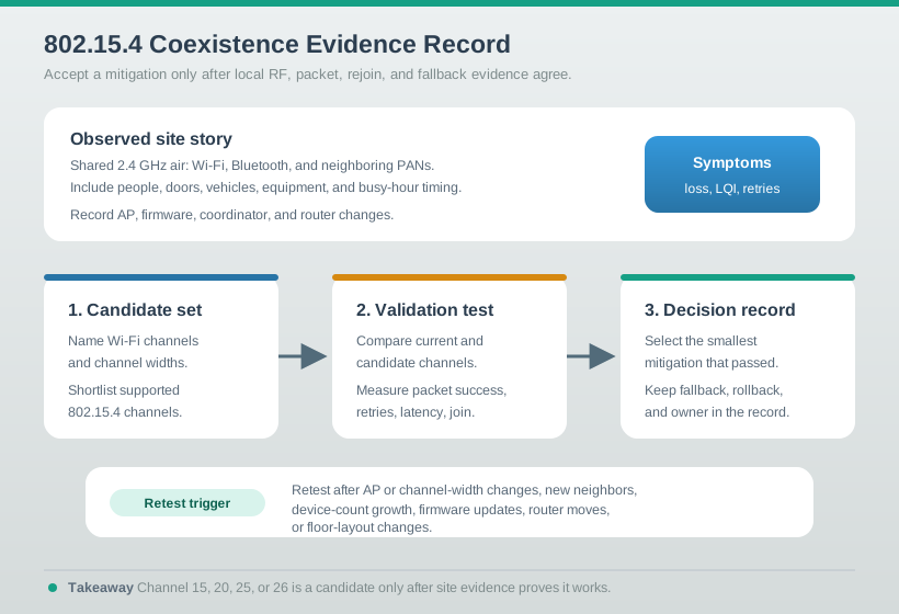
Use Figure 30.2 to keep the decision reviewable. A coexistence fix is not complete until the team records the environment, symptom, candidate tests, decision, fallback, and retest trigger.
30.10 Worked Review Examples
30.10.1 Office Lighting
An office lighting network becomes unreliable after access points are replaced. The sensors still show usable RSSI, but retries and latency increase during work hours.
Review steps:
- Compare failures before and after the access-point replacement.
- Record Wi-Fi channels, widths, and traffic during busy periods.
- Compare packet success and retries on the current 802.15.4 channel and two candidate channels.
- Check whether device rejoin behavior is safe during a maintenance window.
- Accept the channel change only if busy-hour packet success and latency improve.
Do not accept “move to channel 26” as the whole answer. The answer must say why that channel is supported, why it is a better candidate in this site, and what evidence proves improvement.
30.10.2 Warehouse Inventory
A warehouse has many battery tags that report when pallets move. Failures happen when shift changes trigger many events at once.
Review steps:
- Separate RF interference from traffic burst contention.
- Check whether loss occurs on otherwise clean channels.
- Add randomized reporting delay for non-critical movement events.
- Compare retry count, latency, and battery impact before and after staggering.
- Record whether a channel change is still needed after traffic shaping.
If the channel is clean but every device reports at the same time, coexistence is not the main problem. The MAC is being overloaded by synchronized traffic.
30.11 Review Checklist
Before accepting a coexistence decision, verify that:
- interference was distinguished from weak signal, routing, firmware, and burst-load causes
- Wi-Fi channels, widths, and busy periods were observed locally
- candidate 802.15.4 channels are supported by every relevant device
- loss, retries, latency, and join behavior were measured before and after the change
- battery impact is described from measured radio behavior, not a fixed multiplier
- the mitigation matches the cause: channel, Wi-Fi coordination, traffic shaping, topology, or PHY change
- maintenance, rejoin, and fallback steps are documented
- the decision record includes a retest trigger for access-point, device-count, firmware, or layout changes
30.12 Common Mistakes
Avoid these patterns:
- using one universal “safe channel” rule without local evidence
- blaming Wi-Fi when synchronized 802.15.4 traffic is the real cause
- relying on RSSI alone while ignoring LQI, retries, and packet error rate
- testing only during quiet hours
- changing channels without checking rejoin and rollback behavior
- assuming sub-GHz is automatically better without checking region, antenna, hardware, and application data needs
- treating retry storms as a fixed battery multiplier instead of measuring current and radio-on time
- forgetting to retest after access-point changes or new neighboring networks appear
30.13 Knowledge Check
30.14 Matching Quiz
30.15 Ordering Quiz
30.16 The 2.4 GHz Band Is Crowded
802.15.4’s 2.4 GHz band is shared license-exempt spectrum. The same 2400–2483.5 MHz carries Wi-Fi (802.11), Bluetooth and BLE, other 802.15.4 networks, and even microwave-oven leakage. Coexistence is the discipline of keeping a low-power 802.15.4 network reliable while these louder neighbours share the air. The review starts from measured symptoms, not from a favorite channel number.
Three levers do most of the work: choose a channel that dodges the strongest interferers, listen before talking with clear-channel assessment (CCA), and keep the duty cycle low so brief transmissions slip between other traffic. Because an 802.15.4 radio may use about 1 mW while a nearby Wi-Fi access point may use 100 mW or more, the winning move is usually to avoid Wi-Fi energy rather than to out-shout it. A 100 mW transmitter is 100 times the power of a 1 mW transmitter, which is a 20 dB difference; a 1 W transmitter is 1000 times higher, or 30 dB. 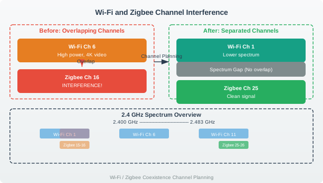
Worked symptom example. A lighting network has 40 wall switches and lamp controllers. Before an access-point replacement, the coordinator sees 98 successful commands out of 100 during a busy hour. After the replacement, RSSI at the coordinator still looks acceptable, but success falls to 88 out of 100, retries triple, and the failures cluster during video meetings. That pattern does not prove the lamps are broken. It says the reviewer should compare Wi-Fi channel and width, local noise, packet loss, retry count, LQI, and latency before changing firmware or replacing devices.
Coexistence also protects battery life. A small sensor that usually sends one report may need several retries when the channel is busy. If the average exchange grows from one attempt to three attempts during the busiest hour, the radio stays awake longer, the parent has more work to do, and application latency becomes variable. Even when every packet eventually arrives, the network can feel unreliable because command completion time is no longer predictable.
Coexistence in one line: pick a quiet channel, sense before sending, stay brief, then prove the result with local packet evidence. A low-power radio should avoid a nearby access point rather than try to overpower it.
30.16.1 Overview Knowledge Check
30.17 Map 802.15.4 Channels Against Wi-Fi 1/6/11
A 2.4 GHz Wi-Fi channel is about 20 MHz wide, so it blankets roughly four of the 5-MHz-spaced 802.15.4 channels. In many deployments Wi-Fi uses the non-overlapping set channels 1, 6, and 11 (centres 2412, 2437, 2462 MHz). Overlaying the two plans shows where candidate gaps may exist, but it does not replace measurement. Wider Wi-Fi channels, high transmit power, nearby access points, and neighboring tenants can erase a gap that looks clean on paper.
| Wi-Fi channel | Approx. span | 802.15.4 channels it covers |
|---|---|---|
| 1 | 2401–2423 MHz | 11, 12, 13, 14 |
| 6 | 2426–2448 MHz | 16, 17, 18, 19 |
| 11 | 2451–2473 MHz | 21, 22, 23, 24 |
The 802.15.4 channels that often fall in the gaps around Wi-Fi 1/6/11 are the classic candidate set: 15 (2425 MHz), 20 (2450 MHz), 25 (2475 MHz), and 26 (2480 MHz). Treat them as candidates, not guarantees. Channel 20 sits in a narrow gap between common Wi-Fi 6 and Wi-Fi 11 plans, so it can be fragile when either Wi-Fi channel is wide or close. Channels 25 and 26 sit above Wi-Fi 11 in a 20 MHz plan, but channel 26 is near the band edge and may have product or regional constraints.
Worked channel example. A site survey shows Wi-Fi on channels 6 and 11. Start by listing the actual centres: 802.15.4 channel 20 is 2450 MHz, channel 25 is 2475 MHz, and channel 26 is 2480 MHz. If packet tests show channel 20 has 12% loss during busy hours while channel 25 has 2% loss and similar latency, channel 25 is the better candidate for that site. If channel 25 is unsupported by some devices, the evidence does not authorize using it; the reviewer must either pick a supported fallback or plan a device change.
Validation example. Suppose the current channel loses 9 commands out of 100 during the busy hour, while a candidate channel loses 2 out of 100 in the same window. That is an improvement, but the acceptance record still needs retry count, latency, join/rejoin behavior, and a rollback path. A channel that improves packet success but causes half the sleepy devices to miss rejoin after maintenance is not acceptable without a recovery plan.
Use the channel map as a shortlist generator. The final decision should name the current channel, candidate channels, device support, Wi-Fi channels and widths, packet success, retry count, latency, battery impact, and the event that triggers retesting. Access-point replacement, channel-width changes, new neighboring Wi-Fi, or a changed floor layout can all invalidate an old coexistence decision.
30.17.1 Practitioner Knowledge Check
30.18 CCA Modes and Frequency Agility
Listen-before-talk depends on how a radio judges “busy.” 802.15.4 defines three CCA modes: Mode 1 (energy detection) flags the channel busy when received power exceeds a threshold, regardless of source; Mode 2 (carrier sense) flags busy only when it detects a valid 802.15.4 signal; Mode 3 combines both. Energy detection sees Wi-Fi and microwave energy, which is useful for coexistence. Pure carrier sense can be blind to non-802.15.4 interferers because it is looking for a recognizable 802.15.4 signal, not just energy.
CCA still has limits. It checks the channel before a frame begins; it does not protect against a hidden interferer that starts after the check, and it cannot make airtime appear when the channel is busy most of the time. If an access point is close to the coordinator and the channel is occupied during most application bursts, an 802.15.4 node can spend its time backing off, failing channel access, or retrying corrupted frames.
CCA example. A sensor wants to send a short alarm. During a quiet hour, energy-detect CCA finds the channel clear on most attempts, so the alarm usually transmits on the first try. During a Wi-Fi-heavy hour, CCA reports busy on many attempts. If the node needs three backoff rounds before it transmits, and the frame is then corrupted by another burst, the application sees both delay and retry energy. The packet problem is now visible as channel-access failures, retry count, and latency, not only as final packet loss.
That is why practical stacks add frequency agility. A network can detect a degraded channel through rising energy, falling delivery ratio, or persistent retries, then migrate the PAN to a cleaner supported channel. The migration is itself a risk: devices must hear the change, move together, rejoin if needed, and preserve application state. A coexistence design should therefore specify when agility is automatic, when it is a maintenance action, and how failed movers are recovered.
Agility example. A Zigbee network on channel 20 runs acceptably until an access point is retuned near Wi-Fi channel 11. Energy-detect CCA starts reporting busy, retries climb, and packet delivery drops in the rooms nearest the access point. A bounded test moves the PAN to channel 25, which the product supports and which measured better during the failure window. Delivery improves without increasing transmit power. The acceptance record should still keep the old channel, candidate results, failed-device recovery procedure, and retest trigger, because coexistence is an ongoing measurement-and-agility loop rather than a one-time channel pick.
30.18.1 Under-the-Hood Knowledge Check
30.19 Summary
802.15.4 coexistence review is about local evidence. Wi-Fi overlap can matter, but so can synchronized 802.15.4 bursts, neighboring PANs, weak links, router placement, firmware changes, and join behavior. A reliable review records symptoms, observes the RF environment, tests candidate mitigations, validates packet and latency improvements, and defines when the decision must be reopened.
30.20 Key Takeaway
802.15.4 Coexistence should treat interference as a deployment evidence problem, balancing channels, duty cycle, retries, placement, and coexistence with nearby Wi-Fi or other radios.
30.21 Concept Relationships
This chapter connects to:
- 802.15.4 Features and Specifications for PHY/MAC features, channel spacing, GTS, and frame budget review.
- 802.15.4 Deployment Considerations for site survey, router placement, and installation evidence.
- 802.15.4 Fundamental Operation for CSMA/CA, retries, acknowledgments, and beacon behavior.
- Wi-Fi Fundamentals and Standards for Wi-Fi channel width and access-point planning context.
- 802.15.4 Comprehensive Review for the broader review gate that combines coexistence with topology, power, security, and frame budget.
30.22 What’s Next
Continue with 802.15.4 Deployment Considerations to review how coexistence evidence fits into physical installation, topology, and site planning.