11 Cellular Architecture for IoT
cellular architecture IoT, LTE IoT architecture, 5G IoT architecture, cellular core network, IoT cellular design review
11.1 Start With the Wireless Story
Cellular architecture matters when one packet crosses many ownership boundaries. Follow the device from radio access through identity, core network, mobility state, data path, and cloud reachability so the IoT service can explain where delays and failures may enter.
11.2 In 60 Seconds
Cellular IoT architecture is a chain of evidence, not just a tower diagram. A device must have a radio and antenna that fit the site, an identity or profile that the operator accepts, a radio access network that can hear it, a core network that can register and route it, and an application path that can carry the intended traffic.
The design review should answer:
- what device, antenna, enclosure, and power state are being reviewed
- what cellular service, operator, region, profile, and supported bands are in scope
- whether the device can register from the intended location
- whether uplink and downlink reachability match the application
- whether mobility, roaming, latency, payload size, and maintenance needs match the selected cellular profile
- what must be retested after firmware, SIM/profile, operator, antenna, enclosure, site, or application changes

Phoebe’s Why
An antenna cannot manufacture energy – gain is not amplification. A base-station panel takes the power fed into it and redistributes it unevenly across space: less energy toward directions nobody needs, more energy toward the sector it actually serves. Directivity compares the power density in the antenna’s favoured direction to what an isotropic radiator – one that spreads power over the full sphere equally – would produce from the same input power, and gain derates that ideal by the antenna’s efficiency. A macro sector antenna trades most of the sphere away on purpose: it does not try to reach anything behind the tower, so every watt it would have wasted there is redirected into the sector that needs to hear a device’s uplink. That is the physics behind “good RSRP” – Reference Signal Received Power measures how much of that concentrated beam actually lands on the device’s antenna, and it says nothing about whether the identity, subscription, or core-network layers behind it will accept the device.
The Derivation
Directivity from an isotropic reference, and gain after efficiency \(\eta\):
\[D = \frac{4\pi}{\Omega_A}, \qquad G = \eta D\]
Effective isotropic radiated power:
\[\mathrm{EIRP} = P_t\,G\]
Approximate directivity from the two half-power beamwidths in degrees (a standard rule of thumb, not exact for a real pattern):
\[D_{approx} \approx \frac{41{,}253\ \text{deg}^2}{\theta_{az}\,\theta_{el}}\]
Because free-space received power falls as \(1/d^2\) (Friis), the range needed to reach a fixed received-power threshold scales with gain as:
\[\frac{d_2}{d_1} = \sqrt{\frac{G_2}{G_1}}\]
Worked Numbers: A Catalog-Typical Macro Sector
- Catalog-typical sector panel: \(G=17\) dBi \(\Rightarrow\) linear \(G=10^{17/10}=50.1\).
- Solid angle actually served: \(\Omega_{sector}=4\pi/G=0.251\) sr, about \(2.00\%\) of the full sphere – the other \(98.0\%\) gets none of that power, on purpose.
- Beamwidth check (\(\theta_{az}=65°\), \(\theta_{el}=6.2°\), catalog-typical): \(D_{approx}=41{,}253/(65\times6.2)=102\), i.e. \(20.1\) dBi – about \(3.10\) dB above the quoted \(17\) dBi. That gap is expected: the beamwidth-product formula ignores sidelobes and aperture taper, so it always over-estimates a real antenna’s directivity by a few dB.
- Range payoff: going from an isotropic reference (\(G=1\)) to this \(50.1\times\) sector gain extends free-space range by \(\sqrt{50.1}=7.08\times\) for the same transmit power and received-power threshold – the same physics behind why “good RSRP” is achievable at cell-edge distances an isotropic radiator never could reach with the same power. RSRP only proves that concentrated 2% of the sphere delivered usable power; it proves nothing about the identity, core, or application evidence this chapter’s review record still has to collect.
11.3 Learning Objectives
By the end of this review, you will be able to:
- trace IoT traffic from device through radio access, cellular core, and application services
- separate radio coverage, subscription, core registration, packet service, and application failures
- explain why power-saving and reachability decisions are architecture decisions
- evaluate cellular technology fit using evidence rather than fixed marketing claims
- document retest triggers for cellular architecture changes
11.4 Architecture Scope
Use this review when a cellular design must be accepted, compared, or repaired. It applies to LTE-M, NB-IoT, 5G IoT profiles, and other operator-managed cellular options, but the final decision always depends on regional service, operator support, module capability, antenna, enclosure, and application requirements.
The review should produce a record with:
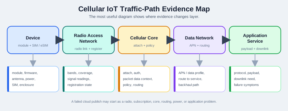
- device evidence: module, firmware, antenna, enclosure, power state, and interface
- identity evidence: SIM, eSIM, profile, subscription, service activation, and operator context
- radio evidence: supported bands, site coverage, signal observations, and registration state
- core evidence: attach, authentication, packet data context, policy, and routing behavior
- application evidence: protocol path, payload pattern, downlink need, backhaul, and failure symptoms
- decision evidence: accepted architecture, accepted with limits, retest required, or redesign required
11.5 Cellular Traffic Path
The most useful architecture diagram shows where evidence changes layer. A failed cloud publish may start as a radio, subscription, core, routing, power, or application problem.
11.6 Device And Radio Access Evidence
Start at the device, because many architecture failures are caused by assumptions made before the network is involved.
Record:
- module and firmware identity
- supported cellular profiles and bands
- antenna type, connector, cable, enclosure, and mounting state
- power source and any resets during attach or transmit attempts
- SIM, eSIM, or profile status
- location, site conditions, and whether the test is bench, pilot, or installed form
Radio access evidence should show whether the device can hear and be heard by a suitable cell from the intended location. A good record ties signal observations to the actual antenna, enclosure, and mounting position.
11.7 Core Network Evidence
After radio access, the core network decides whether the device identity, subscription, service, policy, and packet data path are allowed.
Common review questions:
- Does the SIM or profile match the intended service?
- Is the device registered, searching, denied, roaming, or unknown?
- Does the selected service allow packet data for the application?
- Is the APN or data profile correct for the operator and account?
- Does the core assign routing that reaches the application service?
- Does downlink delivery depend on device wake cycles, paging windows, or application polling?
Do not treat a serial OK response or a signal reading as proof of architecture readiness. Registration and packet-service evidence must be reviewed separately.
11.8 Power, Mobility, And Reachability
Power-saving behavior changes architecture behavior:
- A device in deep sleep may be efficient but not immediately reachable.
- A device that must receive commands quickly may need more frequent listening or a different service profile.
- A mobile asset may need handover and roaming behavior that a fixed sensor does not.
- A stationary buried or indoor device may prioritize coverage and wake-scheduled uplink over continuous reachability.
- Firmware updates, commands, alarms, and diagnostics can change the reachability requirement.
The review should record the required downlink timing, mobility pattern, payload size, and maintenance path before choosing a cellular profile.
11.9 Technology-Fit Review
Cellular options should be compared through evidence categories, not fixed universal rankings.
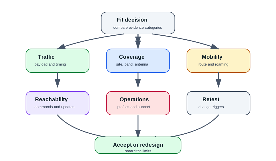
Use the map to structure the decision:
- Traffic pattern: small periodic uplink, event-driven alarm, command-response, firmware update, or higher-rate data stream
- Coverage evidence: installed location, antenna and enclosure state, supported bands, and operator service
- Mobility evidence: stationary, portable, moving asset, roaming region, and handover need
- Reachability evidence: how soon commands, updates, or alarms must reach the device
- Operations evidence: provisioning, profile management, monitoring, support process, and retest triggers
11.10 Decision Options
Each architecture finding should lead to a bounded decision:
- Keep the selected cellular profile when device, coverage, subscription, core, and application evidence all support the claim.
- Retest with installed antenna or enclosure when bench evidence differs from final form.
- Change service profile or operator setup when registration or packet service fails despite suitable radio evidence.
- Change antenna, placement, or enclosure when radio evidence fails before core registration can be judged.
- Change cellular technology when traffic, mobility, reachability, or coverage needs do not match the selected profile.
- Change application behavior when the device architecture is sound but the application assumes immediate downlink or continuous connectivity.
- Escalate to operator or account support when the evidence points to subscription, roaming, policy, or provisioning limits.
Change one architecture variable at a time during diagnosis whenever possible.
11.11 Review Record Template
For each cellular architecture review, record:
- device, module, firmware, antenna, enclosure, power state, and location
- operator, region, SIM/eSIM/profile, subscription, and service context
- supported bands and selected cellular technology
- signal and registration observations
- packet service or data context evidence
- APN, routing, policy, or account constraints, with secrets redacted
- application protocol, payload pattern, uplink and downlink needs
- mobility and roaming assumptions
- first failing layer, if any
- decision, limitation, next action, and retest trigger
11.12 Worked Review: Fixed Indoor Meter
Scenario: a fixed indoor meter sends small periodic readings and only needs delayed maintenance commands.
Good review sequence:
- Confirm the device, antenna, enclosure, mounting, and power state.
- Confirm operator, profile, subscription, supported bands, and service activation.
- Capture signal, registration, and packet-service evidence from the installed location.
- Check whether downlink commands can wait for the device’s scheduled wake or uplink behavior.
- Record whether the selected cellular profile supports the coverage and reachability claim.
Accepted answer: “The architecture decision depends on installed coverage, registration, packet service, and downlink timing evidence. A generic battery-life claim is not enough.”
11.13 Worked Review: Moving Asset Tracker
Scenario: a tracker moves through several regions and must report events while in motion.
Good review sequence:
- Record mobility route, roaming or operator context, and supported bands.
- Check whether the selected service supports the expected movement and regional coverage.
- Review registration behavior across representative locations.
- Review payload size, event timing, and downlink command needs.
- Record retest triggers for new region, antenna, enclosure, firmware, profile, or operator changes.
Accepted answer: “Mobility and regional service evidence are part of architecture fit. A stationary-device assumption cannot be reused for a moving asset without retest.”
11.14 Common Mistakes
- treating signal quality alone as proof that the cellular architecture is ready
- ignoring SIM, eSIM, profile, subscription, APN, or account policy evidence
- assuming one cellular technology is always best for every IoT workload
- using bench antenna evidence as final installed evidence
- choosing power-saving behavior before documenting downlink reachability needs
- ignoring mobility, roaming, and regional service requirements
- mixing radio, core, backhaul, and application failures into one vague “cellular problem”
- publishing secrets, subscriber identifiers, APNs, or credentials in review records
- omitting retest triggers after firmware, profile, operator, antenna, enclosure, site, or application changes
11.15 Knowledge Check: Cellular Architecture
11.16 Match The Architecture Evidence
11.17 Order The Cellular Architecture Review
11.18 Review Checklist
Before accepting the cellular architecture review, confirm that the record includes:
- device, module, firmware, antenna, enclosure, power state, and location
- operator, region, SIM/eSIM/profile, subscription, and service activation context
- supported bands and selected cellular technology
- signal, registration, and packet-service evidence
- APN, data profile, routing, policy, and account constraints with secrets redacted
- application protocol path, payload pattern, uplink and downlink needs
- mobility, roaming, and regional assumptions
- first failing layer for any failed test
- architecture decision and limitations
- retest triggers after firmware, SIM/profile, operator, antenna, enclosure, site, routing, or application changes
11.19 Base Station Plus Core, Split Into Two Planes
A cellular network has two halves: the radio access network (the base stations — an eNodeB in LTE, a gNB in 5G) and the core network behind it. The core does the work a device never sees: authenticating the SIM, tracking which cell the device is in, and routing its data to the internet.
The core separates a control plane (signalling: who you are, where you are, setting up connections) from a user plane (the actual data packets). In LTE the core is the EPC; in 5G it is the service-based 5G Core (5GC). For IoT, this split is the key to efficiency, because tiny messages should not pay the full price of user-plane setup.
That split also gives the review a clean failure order. First prove that the installed device can hear and be heard by the RAN with its real antenna, enclosure, and power state. Next prove that the control plane accepts the identity, location, mobility, and service request. Only after those two claims are true does a failed MQTT, CoAP, HTTPS, or private APN path become an application or routing problem rather than a vague cellular problem.
A useful architecture note therefore names the first missing proof. “Good RSRP but attach denied” points at identity, subscription, roaming, or policy. “Attached but no packet data context” points at APN, service profile, or core routing. “Packet data works but downlink commands arrive late” points at paging, sleep state, polling, or application timing. The diagram is a checklist for separating those claims.
Mental model: eNodeB/gNB = the radio; EPC/5GC = the brain, and the brain keeps “who/where” (control plane) separate from “the data” (user plane). A design is ready only when the review has evidence at each boundary, not just a signal bar.
11.19.1 Overview Knowledge Check
11.20 EPC Elements, 5GC Equivalents, and RRC States
The LTE EPC has a small cast, each mirrored by a 5GC network function:
| Role | LTE (EPC) | 5G (5GC) |
|---|---|---|
| Control: auth, mobility | MME | AMF |
| Session management | (part of MME/S-GW) | SMF |
| User-plane gateway | S-GW + P-GW | UPF |
| Subscriber database | HSS | UDM |
Older GSM and UMTS diagrams use different names, but the review habit is the same. A BSC or RNC controls radio resources at the base-station edge. An MSC handles circuit-switched mobility and call control. An SMSC stores and forwards text messages. The HLR and VLR are subscriber and visitor-location databases, and SS7 is the signalling fabric that lets those systems ask who the device is, where it is, and which service or billing state is allowed.
For an IoT architecture review, those legacy boxes are not trivia. They are control-plane proof points: identity, location, roaming, service policy, prepaid or billing status, and message-store behavior must line up before the user-plane packet path, voice path, or application workflow can be trusted.
| Legacy cellular name | Review question it represents |
|---|---|
| BSC / RNC | Which radio controller owns handoff, channel, and base-station resource evidence? |
| MSC | Which switch or control function handles mobility, call setup, and service reachability? |
| SMSC | Where are short messages stored, retried, or dropped before the application sees them? |
| HLR / VLR | Which database proves subscriber identity, home service, visited location, and roaming state? |
| SS7 | Which signalling path carries identity, location, routing, and service-control requests? |
A device’s radio link has RRC states. In RRC_IDLE it has no active connection and is only paged for downlink; in RRC_CONNECTED it has a live radio connection for data. 5G adds RRC_INACTIVE, which keeps the device’s context so it can resume quickly without a full setup. 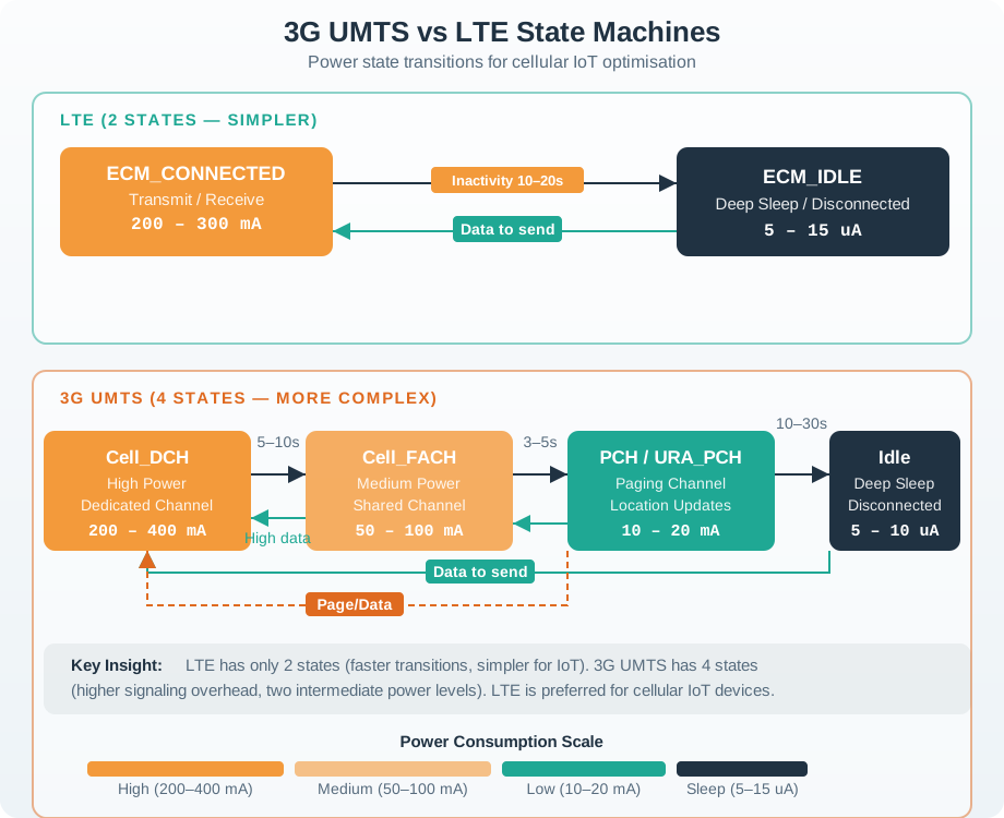
In a field record, do not collapse those names into “the network.” If the module reports a serving cell but never reaches an attached or registered state, the practitioner should collect registration reject codes, profile status, operator context, and roaming allowance before changing antennas. If attach succeeds but data does not start, the next evidence is bearer or packet data context, APN or data profile, assigned address, policy, and route to the application network. If packets move only after repeated wakes, the RRC and paging behavior are now part of the architecture evidence.
The practical handoff is a small ledger: observed state, first failing transition, evidence source, and next variable to change. Example rows might be “IDLE to CONNECTED succeeds from installed enclosure,” “attach denied on the intended profile,” or “UPF or P-GW path reaches private endpoint but application authentication fails.” This style prevents expensive retests that change firmware, SIM profile, antenna placement, and cloud credentials at the same time.
Worked example. An LTE-M tracker wakes to send a position. It transitions IDLE → CONNECTED, the MME authenticates and sets up the path through S-GW/P-GW, data flows, then it returns to IDLE. For a smartphone streaming video this setup cost is negligible; for a tracker sending 20 bytes it is enormous overhead — which is the problem the IoT optimizations below solve.
11.20.1 Practitioner Knowledge Check
11.21 CIoT Optimizations for Small Data
Setting up a full user-plane path to move 20 bytes is wasteful, so 3GPP defined CIoT EPS optimizations. The Control-Plane optimization (mandatory for NB-IoT) carries the small payload inside control-plane signalling (NAS messages) to the MME, skipping data-radio-bearer setup entirely — ideal for rare, tiny messages. The User-Plane optimization instead lets the device suspend and resume its connection (keeping context, like RRC_INACTIVE), avoiding a full re-establishment for slightly larger or more frequent traffic.
A companion feature, Non-IP Data Delivery (NIDD), ships the payload without an IP header through the SCEF (Service Capability Exposure Function) straight to the application server. For a device whose whole message is a few bytes, an IP/UDP header would be pure overhead; NIDD removes it.
The design choice is a boundary decision, not a feature checklist. Control-plane small data is strongest when the payload is tiny, infrequent, tolerant of operator exposure functions, and not trying to behave like a normal IP session. User-plane resume is stronger when the device sends bursts, needs familiar IP transport, or must reuse a session without paying the full connection setup every time. NIDD is useful only if the operator path, application integration, security review, and support model all exist for that deployment; otherwise an ordinary IP path may be simpler even if it carries more header overhead.
Under-the-hood review should therefore record what overhead is being avoided and what new dependency is introduced. A water meter that sends a short reading every hour may reasonably trade direct IP visibility for lower signalling and energy. A tracker that sends event bursts, expects acknowledgements, or downloads configuration may need user-plane behavior despite the extra setup. If a later firmware release changes the payload size, acknowledgement pattern, encryption wrapper, or downlink timing, the optimization choice must be retested rather than inherited from the old architecture.
Worked example. An NB-IoT water meter sends 12 bytes once an hour. With Control-Plane optimization and NIDD, those 12 bytes ride NAS signalling to the MME and exit via the SCEF to the utility’s server — no data bearer set up, no IP header attached. Compared with the smartphone path (bearers through S-GW/P-GW, full IP stack), it is a fraction of the signalling, airtime, and energy: the same network, re-plumbed for tiny data.
11.21.1 Under-the-Hood Knowledge Check
11.22 Summary
Cellular architecture review connects device evidence, radio evidence, identity evidence, core network evidence, and application evidence. The design is ready only when the whole path supports the deployment claim. Useful records avoid universal battery, cost, or range promises and instead show what was tested, what layer failed first, what decision follows, and what changes require retest.
11.23 Key Takeaway
Cellular Architecture for IoT should compare mobile wireless choices using coverage, capacity, spectrum rules, propagation, power, cost, resilience, and deployment evidence.
11.24 Concept Relationships
- Cellular spectrum explains why operator support, region, and supported bands shape architecture fit.
- Cellular modem labs provide the AT-command evidence used to prove registration and packet-service readiness.
- Coverage planning labs connect architecture assumptions to installed signal and site evidence.
- Propagation design explains why antenna, enclosure, and location change cellular results.
- Mobile wireless review compares cellular architecture evidence with Wi-Fi and other wireless options.
11.25 What’s Next
- Cellular Spectrum for IoT reviews cellular band and operator context.
- Lab: Cellular Modem Bring-Up shows how to collect registration and packet-service evidence.
- Lab: Coverage Planning connects cellular observations to site coverage decisions.
- Wireless Propagation and Design explains antenna, enclosure, and location effects.
- Mobile Wireless Comprehensive Review compares cellular architecture fit with other wireless options.