Chapters

13 Zigbee Network Topologies

zigbee-thread
zigbee
topology
commissioning

13.1 Start With One Packet Path

13.1.1 Break One Route on Purpose

A hotel room reports that a window is open. The first route works through a powered room unit and reaches the desk. During cleaning, that powered unit is unplugged. A label saying mesh does not tell the hotel manager whether the warning finds another path, waits safely, or disappears without a trace.

Draw the exact path used by that room. Name the starting unit, each helper, the central owner, and the desk record that proves arrival. Mark which units sleep, which can pass traffic onward, and which depend on a parent. A network shape becomes useful only when those roles match what the installed units actually do.

Then unplug one helper. Move a sleepy unit to a new parent. Restore power after several minutes. Send the same warning twice. Check route repair, delay, duplicate handling, battery cost, and the visible state at the desk. Repeat the run at the busiest hour, not only in an empty test room.

This test does not prove that every point always has two good paths. It proves the observed recovery for one installed route and condition. The deeper sections compare star, tree, and mesh shapes, then connect parent choice, repair, range, energy, and central boundaries to evidence.

Keep the route review concrete. Which unit sent the event? Which helper heard it first? Which parent did the sleepy unit use? How old was the route? What changed when a helper went dark? How long did repair take? Did the desk receive one useful event? Did a battery unit spend more power? Could the operator see the break?

Answer with a trace, not a shape name. Repeat the run in the real room. Move one unit at a time. Note walls, doors, power, and crowd level. Keep the failed trace beside the good one. That record shows where another helper or a new parent rule may help, and where the design still has only one path.

Start with one packet path through Zigbee Network Topologies. Name the sender, the next hop, the parent or router decision, and the evidence that proves the packet arrived for the reason the design expected.

Then widen the review. Mesh protocols fail at boundaries: sleepy children, route repair, parent changes, multicast, retries, and gateway custody. The chapter is easier to read when every detail is tied back to that first path.

Overview: What a Zigbee Topology Claim Means

Zigbee topology review asks whether the network shape matches observed coordinator, router, and end-device behavior. Star, tree, and mesh are useful words, but they are not proof by themselves. A reviewable topology claim names the deployment boundary, identifies the node roles, records parent relationships, and states what route or recovery behavior was actually observed.

The safest beginner rule is simple: approve only the topology behavior that the record can support. A small direct network can be acceptable when the direct coordinator dependency is intentional. A tree can be acceptable when parent and branch behavior are understood. A mesh can be acceptable when route diversity has been observed where resilience is required.

Radio Remi, the wireless guide

Radio Remi

“Range, power, and data-rate is a triangle — pick two honestly, then measure the third in the real room.”

Through this chapter, Remi checks each topology claim for its role evidence, its trade, and what the site must show.
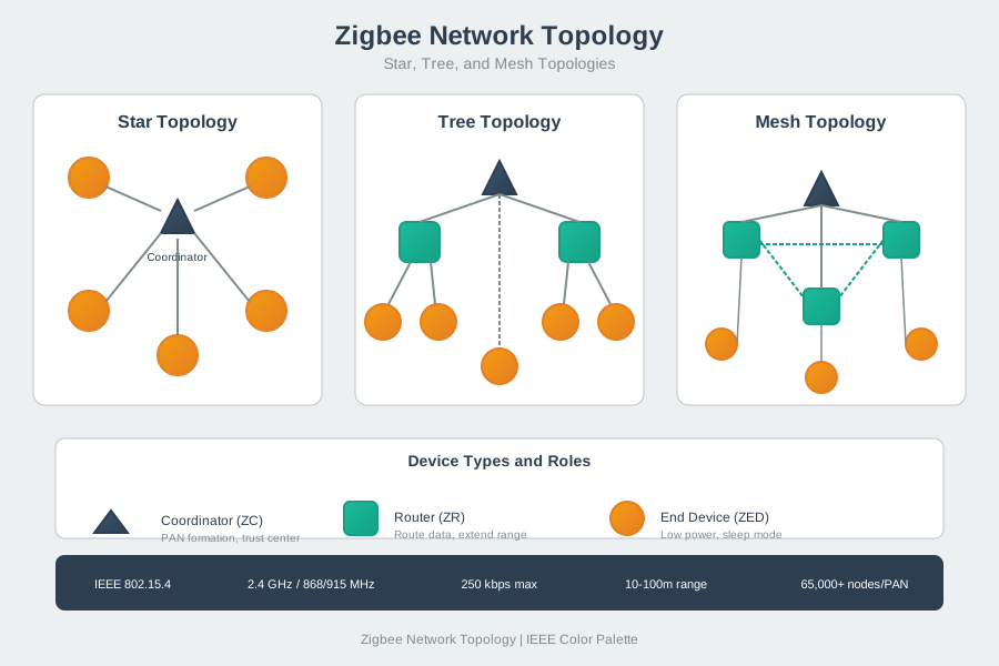
Before overview: What a Zigbee Topology Claim Means, inspect Figure 13.1 to compare “Coordinator” with “10-100m range”. Their juxtaposition makes A topology claim should connect the network shape to observed coordinator, router, and end-device roles before it is used as release evidence visible.

Zigbee network topology comparison showing star, tree, and mesh topologies plus coordinator, router, and end-device roles.
Figure 13.1: A topology claim should connect the network shape to observed coordinator, router, and end-device roles before it is used as release evidence.

Read Figure 13.1 from “Coordinator” to “10-100m range”. Taken together, “Coordinator” and “10-100m range” express A topology claim should connect the network shape to observed coordinator, router, and end-device roles before it is used as release evidence. For overview: What a Zigbee Topology Claim Means, the observed relationship between “Coordinator” and “10-100m range” is evidence that “Coordinator” carries into the next decision.

If you only need the intuition, this layer is enough: a topology diagram is a hypothesis. The evidence record turns that hypothesis into a bounded release decision.

Topology Evidence Families

Star evidence

Records direct coordinator dependencies, the small boundary where they are acceptable, and the site change that requires retesting.

Tree evidence

Records parent-child structure, branch dependencies, orphan behavior, and the owner for parent changes.

Mesh evidence

Records router participation, observed alternate paths, route-change behavior, and weak zones that still have one dependency.

Operations evidence

Records who owns powered routers, coordinator custody, topology refresh, recovery drills, and retest triggers after changes.

Beginner Examples

  • A device appearing online proves a narrow reachability observation, not parent quality, route diversity, or recovery behavior.
  • A powered device near an end device might be a router, but the topology record should show the actual role and parent relationship.
  • A mesh claim can be partly true: one monitored path may have observed alternatives while another area remains dependent on one parent.

Overview Knowledge Check

Practitioner: Build a Topology Evidence Record

A practical topology review starts with a decision claim. The claim should say what behavior is being approved, where it applies, and what evidence makes it ready. The record should then separate role evidence from path evidence so a tidy diagram does not hide fragile dependencies.

For each important device or zone, record the coordinator boundary, selected parent or next hop, expected router role, observed alternate path when resilience is required, and the change that makes the record stale. This keeps topology review useful after devices move, routers lose power, firmware changes, or a gateway is replaced.

Record Field
Review Question
Evidence To Record
Common Overclaim
Boundary
Where does the topology claim apply?
Room, floor, site, pilot group, excluded areas, coordinator or gateway boundary, and operating condition.
"The whole product is ready because one area was observed."
Role map
Which nodes acted as coordinator, routers, and end devices?
Coordinator custody, powered routers expected to stay available, sleepy end devices, role changes, and owner for each role.
"The inventory proves which devices routed traffic."
Parent and route evidence
Which dependencies did important devices actually use?
Parent relationships, next hops, route changes, observed alternate paths, unsupported paths, and weak zones.
"A mesh diagram means every device has a good alternate path."
Decision and retest
What is approved, what is outside scope, and when must the record be refreshed?
Accept/revise/retest decision, known gaps, operations owner, device move, router loss, coordinator change, traffic change, or site change.
"The topology remains approved after any maintenance change."

Worked Review: Small Direct Network

A small monitored area shows every reviewed end device reporting directly through the coordinator. The practitioner decision can accept a bounded star claim if the direct dependency is intentional, the coordinator placement is stable, no hidden router dependency was found, and operations knows what move or added device requires retesting.

Remi’s Signal Check

  • Band: a small monitored area where every reviewed end device reports directly through the coordinator — a bounded star claim.
  • Trade: direct dependency is fine when it is intentional and the coordinator placement is stable — not fine as an accident.
  • Room test: confirm no hidden router dependency, and record what added device requires a retest.

Worked Review: Router Removed From a Mesh

A powered router is removed during maintenance and nearby end devices reconnect through a different parent. The review should compare parent evidence before and after removal, check whether application behavior still matches the release claim, and narrow the decision to the paths that actually recovered. Devices that moved to fragile parents remain outside the approved mesh claim until revised or retested.

Trace one concrete path before generalizing. Suppose a seven-router mesh normally lets router A reach coordinator G by relaying through routers C and F, among others. If C and F both fail at once, a mesh diagram alone does not answer whether A is now cut off. Route diversity is the fact that A can still reach G along a different chain of routers — here, relaying through B, D, and E instead. That alternate path, not the phrase "the mesh healed," is the evidence worth recording: which routers failed, which routers carried the recovered traffic, and whether the recovered path meets the same latency and reliability expectation as the one it replaced before it is approved as equivalent.

Practitioner Knowledge Check

Under the Hood: Role Dynamics, Route Drift, and Retest Triggers

Under the hood, Zigbee topology is dynamic. End devices select parents, routers may participate in forwarding, routes can be repaired, and application behavior can continue or fail after the network path changes. The review should preserve those dynamics instead of freezing the network as a static drawing.

The most important boundary is between what was observed and what was assumed. A route table snapshot, gateway inventory, or diagram can support a record, but it should not replace failure drills, parent-change evidence, route-change evidence, and owner decisions for maintenance events.

Dynamic Event
What To Inspect
Failure Pattern
Retest Trigger
Parent change
End-device parent before and after the event, path quality, latency, report freshness, and application impact.
The device appears online but is now dependent on a weaker parent or an overloaded branch.
Device move, battery behavior change, router move, wall power change, enclosure change, or local interference change.
Router loss
Which devices used the router, which devices recovered, which devices moved to a fragile path, and which owner approves the new state.
The network repairs for some devices while a critical zone silently loses redundancy.
Maintenance removal, outlet use change, firmware update, replacement device, or planned power policy change.
Coordinator or Trust Center change
Custody owner, join policy, address and security effects, rejoin behavior, backup plan, and support runbook.
Topology is treated as unchanged even though the root of network custody changed.
Coordinator replacement, backup restore, security policy change, gateway bridge change, or ownership transfer.
Scaling change
New zones, added reporting traffic, group commands, retries, router capacity, weak links, and split-network boundary.
A design that worked in a small pilot is approved for a larger site without renewed path evidence.
Device count growth, new floor or room, traffic pattern change, alert latency change, or added automation rule.

Remi’s Signal Check

  • Band: a coordinator or Trust Center change resets custody, join policy, address and security effects, and rejoin behavior.
  • Trade: a design that worked in a small pilot needs renewed path evidence at a larger site — new zones, traffic, router capacity, weak links.
  • Room test: retest after coordinator replacement, backup restore, security-policy change, or device-count growth.

The scaling row deserves a separate decision surface because expansion changes several boundaries at once. Compare the evidence that supported the pilot with the evidence required for the larger deployment: node count is a retest trigger, not proof of capacity, and additional routers are possible paths rather than demonstrated resilience.

Before under the Hood: Role Dynamics, Route Drift, and Retest Triggers, inspect Figure 13.2 to compare “bridge load” with “RETEST WHEN”. Their juxtaposition makes scaling approval is bounded to the observed site, roles, paths, workload, latency, and recovery evidence. New zones, parent or router load, weak RF areas, group commands, automation, or support changes require renewed evidence before the larger claim is approved visible.

Zigbee scaling review diagram comparing an evidence-bounded pilot claim with a proposed larger deployment. Five parallel evidence dimensions cover boundary and roles, parents and router load, RF paths and weak zones, traffic and latency, and operations and recovery. They feed a bounded decision to approve only the evidenced scale, limit or split the deployment, or retest and redesign. A footer lists changes that make the evidence stale. The figure warns that node count and additional routers do not by themselves prove capacity or resilience.
Figure 13.2: Scaling approval is bounded to the observed site, roles, paths, workload, latency, and recovery evidence. New zones, parent or router load, weak RF areas, group commands, automation, or support changes require renewed evidence before the larger claim is approved.

Read Figure 13.2 from “bridge load” to “RETEST WHEN”. Taken together, “bridge load” and “RETEST WHEN” express scaling approval is bounded to the observed site, roles, paths, workload, latency, and recovery evidence. New zones, parent or router load, weak RF areas, group commands, automation, or support changes require renewed evidence before the larger claim is approved. For under the Hood: Role Dynamics, Route Drift, and Retest Triggers, the observed relationship between “bridge load” and “RETEST WHEN” is evidence that “bridge load” carries into the next decision.

Read the five evidence dimensions in parallel. If any new zone, parent path, traffic pattern, router load, alert latency, or recovery duty remains unproved, narrow or split the decision rather than generalising the pilot. The diagnosis pattern next preserves the original record, retests the changed boundary, and approves only the behaviour the renewed evidence supports.

Diagnosis Pattern

  1. Name the exact topology claim. Separate a direct reachability claim from a route-diversity or recovery claim.
  2. Preserve role and parent evidence. Record coordinator custody, router role, parent choice, route observations, and application symptoms before changing anything.
  3. Retest the changed boundary. A moved router, changed gateway, new firmware, or larger traffic load invalidates different parts of the topology record.
  4. Narrow the decision. Approve the paths that recovered, flag paths that became fragile, and write the unsupported claim explicitly.

Under-the-Hood Knowledge Check

13.2 Zigbee Network Formation

13.2.1 Start With One Packet Path

Make the First Join a Controlled Event

Zigbee is a low-power wireless system for nearby devices. Picture a care-home team adding thirty room sensors while an unknown unit is also trying to join. A green setup screen is not enough. The installer must prove which unit joined, who allowed it, and which network now owns it.

Start with one labelled sensor. Record its identity, the chosen radio channel, the network name, the device that grants entry, the open-join period, the first parent, the key record, and the final time. Close entry as soon as the planned group is complete.

Repeat the join beside a weak parent, after a power cut, and while the coordinator is busy. Try an unlisted unit and an old approved unit. The first must stay out. The second must either return through an approved path or leave a clear failure record.

Joining only proves network membership. It does not prove that an alarm reaches the care service, that commands are allowed, or that a sensor reading is sound.

Practitioner builds the formation record and release check. Under the Hood explains parent choice, counters, key custody, and how a changed channel or coordinator can make old evidence unfit for a new release.

Use this controlled-join check:

  • Label the unit before power-up.
  • Record the chosen radio channel.
  • Record the network name and owner.
  • Open entry for a set time.
  • Join only the planned unit.
  • Close entry as soon as done.
  • Try one unit not on the list.
  • Restart the unit and parent.
  • Move beside a weaker parent.
  • Confirm the first message path.
  • Record keys without exposing them.
  • Reopen after any coordinator change.

Start with one packet path through Zigbee Network Formation. Name the sender, the next hop, the parent or router decision, and the evidence that proves the packet arrived for the reason the design expected.

Then widen the review. Mesh protocols fail at boundaries: sleepy children, route repair, parent changes, multicast, retries, and gateway custody. The chapter is easier to read when every detail is tied back to that first path.

Overview: Formation Is the Network's First Evidence Record

Zigbee network formation is the review record that explains how a coordinator created a network and how devices were allowed to join it. A useful record does not stop at "the device joined." It names the deployment boundary, channel and PAN decision, Trust Center custody, joining rule, association result, selected parent, application observation, owner, and retest trigger.

The beginner mistake is to treat formation as a setup screen. Formation is a release gate. It decides whether the network identity, joining authority, and first parent relationships are controlled enough to support the actual product behavior.

Formation establishes the channel, network identity, join window, and initial key custody that every later observation assumes. Figure 13.3 shows those decisions in the order they occur.

Zigbee network formation in four steps: the coordinator performs an energy scan to select the lowest-interference channel among channels 11 to 26, chooses a PAN ID and short address, enables permit-join by broadcasting beacons, and associates joining routers and end devices, assigning each a short address and network key through the trust center.
Figure 13.3: Formation approval should follow one bounded evidence flow: claim, channel and PAN evidence, Trust Center custody, controlled joining, association, key transport, operations owner, and retest trigger.

Step 1 Channel Selection in Figure 13.3 has the Coordinator scan channels 11–26 and choose the lowest-interference result. 2 PAN ID Selection then establishes the example 0x1234 network with coordinator address 0x0000. In 3 Permit Joining, JOIN: ENABLED is a bounded beacon window of 60–255 seconds, not a permanent mode. 4 Device Association Process passes an association request to the Trust Center, which returns the response and network key before routers and sleeping end devices appear in the formed topology. The short addresses 0x0001, 0x0002, and ED 0003–0006 are therefore outcomes of controlled association, carrying the chapter from initial formation into the custody and retest record below.

  1. Radio Remi helps a coordinator compare several unlabeled radio-activity traces before choosing a channel or forming a network.

    First, scan for a clear radio channel.

  2. The coordinator selects one channel and establishes one bounded network identity while Remi confirms the choice.

    Choose the channel and one network identity.

  3. Remi opens a timed join gate for one planned heart-marked care sensor while a different unlisted sensor stays outside.

    Open joining for a set time.

  4. The planned sensor sends an association request through one selected parent router toward a separate trust service.

    The planned sensor asks a parent to join.

  5. The separate trust service returns symbolic protected key and short-address tokens through the parent to the planned sensor.

    The trust service approves the key and address.

  6. Remi closes and locks the join gate, then traces one test message from the joined sensor through a router to the care service.

    Close joining. Then test the first message path.

CW-0004 walkthrough: a controlled join moves from channel and network selection through a timed gate, parent, trust decision, assigned credentials, gate closure, and a separate path test.

If you only need the intuition, this layer is enough: a successful join is evidence for one bounded event. It is not proof that future devices, replacement devices, changed channels, or open joining are safe.

Formation Evidence Families

Channel and PAN

Records the chosen wireless channel, network identity, coordinator persistence, nearby-network observations, and retest rule.

Trust Center custody

Records who controls joining, which commissioning method is allowed, how join material is protected, and where logs live.

Join and association

Records which device joined, which join permission was active, which parent accepted it, and whether key transport completed.

Operations decision

Records accept, revise, reject, or retest; the owner of future joins; and the change that makes the record stale.

Beginner Example

An installer opens joining for three expected devices. Three expected identities and one unknown identity appear. The network formed and devices joined, but the release decision should be revised until the unexpected identity is explained, removed, quarantined, or explicitly accepted under the custody rule.

Overview Knowledge Check

Practitioner: Build the Formation and Join Record

A practical formation review starts with a claim that has boundaries. The claim should say which coordinator, site boundary, channel and PAN decision, device set, join method, and application behavior are being approved. Everything outside that observed boundary stays out of scope until it is reviewed.

How It Works: Controlled Formation

  1. Define the boundary. Name the site, pilot area, coordinator or gateway, expected device classes, and excluded conditions.
  2. Record channel and PAN evidence. Capture why the channel and network identity were accepted and what change requires a fresh review.
  3. Name Trust Center custody. State who can approve joining, how join material is protected, and how logs are preserved.
  4. Open joining deliberately. Record who opened joining, why, where, for which devices, and how it was closed.
  5. Verify the joined state. Record identity, role, selected parent, key transport result, application observation, owner, and retest trigger.

Intermediate Example

A failed sensor is replaced with a new unit that should inherit the same role. A reviewable decision does not approve the replacement from gateway visibility alone. It records the old identity, new identity, approved join window, Trust Center approval path, selected parent, key transport result, expected application behavior, and updated owner record.

Formation Review Ledger

Record Field
Review Question
Evidence To Record
Common Overclaim
Boundary
Where does the formation claim apply?
Coordinator, site or pilot area, expected device set, excluded areas, and operating condition.
"The whole product is ready because one device joined."
Custody
Who controls network formation and joining?
Trust Center owner, approved commissioning method, permit-join owner, log source, and backup or replacement rule.
"Joining authority is just a technical default."
Association
What actually happened when the device joined?
Device identity, intended role, selected parent, association result, key transport result, and application observation.
"Gateway-visible means all join evidence is complete."
Decision
What is approved and when must it be retested?
Accept/revise/reject/retest decision, known gaps, operations owner, and trigger for channel, coordinator, device, or topology changes.
"Formation remains approved after any maintenance change."

Worked Review: Controlled Join Window

An installer opens joining to add a small group of devices. The record compares expected identities with joined identities, confirms who opened joining, checks the Trust Center decision, records which parent accepted each device, closes joining, and states whether the result is accepted or revised. An unexpected identity changes the decision even if every expected device also joined.

Before worked Review: Controlled Join Window, inspect Figure 13.4 to compare “Retest trigger” with “Application evidence”. Their juxtaposition makes the join evidence record keeps custody, permit-join control, selected parent, key transport, application observation, owner, and retest trigger in one reviewable artifact visible.

Zigbee join evidence record listing claim boundary, channel and PAN decision, Trust Center custody, permit-join owner, device identity, selected parent, key transport result, application evidence, decision owner, and retest trigger.
Figure 13.4: The join evidence record keeps custody, permit-join control, selected parent, key transport, application observation, owner, and retest trigger in one reviewable artifact.

Read Figure 13.4 from “Retest trigger” to “Application evidence”. Taken together, “Retest trigger” and “Application evidence” express the join evidence record keeps custody, permit-join control, selected parent, key transport, application observation, owner, and retest trigger in one reviewable artifact. For worked Review: Controlled Join Window, the observed relationship between “Retest trigger” and “Application evidence” is evidence that “Retest trigger” carries into the next decision.

Practitioner Knowledge Check

Under the Hood: Formation Evidence Can Drift

Under the hood, formation evidence becomes stale when the channel environment changes, the coordinator or gateway is replaced, joining authority changes, devices are moved, parents change, or replacement devices enter the network. The review should treat these events as retest triggers instead of assuming the original setup remains valid forever.

The most important separation is between network-side evidence and application-side evidence. A device may associate and receive network material, but the product still needs to prove the expected report, command, state, or gateway-visible behavior after joining. Conversely, application visibility should not erase missing custody or parent-selection evidence.

Formation Drift Patterns

Setup drift

A successful setup screen is treated as release evidence even though the boundary, owner, and retest trigger were never recorded.

Open-join drift

Joining remains easy for installers but becomes unclear for support, security review, and unexpected-device investigation.

Parent drift

A device joins through an unexpected parent, then the topology and routing consequences are missed because the device appears online.

Replacement drift

A new device inherits an old role without fresh identity, custody, key transport, parent, and application evidence.

Diagnosis Pattern

  1. Start with the stale claim. Decide whether the old evidence still covers the channel, coordinator, device, parent, and application boundary.
  2. Preserve custody evidence. Record who opened joining, how the Trust Center decision was made, and which logs can support later troubleshooting.
  3. Inspect the parent relationship. A replacement or rejoin can change parent dependencies even when the gateway shows the device online.
  4. Narrow the decision. Accept only the observed formation behavior and write any unsupported future join, replacement, or topology claim explicitly.

Under-the-Hood Knowledge Check

13.2.2 Summary

Zigbee network formation review is about custody and evidence. A strong record explains the channel and PAN decision, Trust Center owner, controlled join window, joined identities, selected parents, key transport result, application observation, operations owner, and retest trigger.

Do not let a successful join become an unbounded deployment claim. Keep formation evidence tied to the reviewed site boundary and refresh it when the coordinator, channel environment, device identity, parent relationship, or operations rule changes.

Key Takeaway

Approve Zigbee network formation only when channel, PAN, Trust Center, join, parent, application, owner, and retest evidence all support the exact deployment boundary.

13.2.3 See Also

Zigbee Network Topologies

Review coordinator, router, end-device, parent, and route evidence after formation creates the network boundary.

Zigbee Routing

Use this when selected parents and router participation need route discovery, repair, and recovery evidence.

Zigbee Security

Use this for Trust Center custody, key handling, joining approval, and security evidence boundaries.

Zigbee Application Profile Evidence Review

Connect successful joining to clusters, endpoints, and product behavior after commissioning.

13.3 Summary

  • Zigbee topology review starts with a bounded claim, not with a diagram or protocol label.
  • Star evidence proves direct coordinator dependencies only inside the reviewed boundary.
  • Tree evidence records parent-child structure, branch dependencies, orphan behavior, and owner decisions.
  • Mesh evidence needs observed router participation, route alternatives, and route-change behavior where resilience is claimed.
  • Operations evidence keeps the topology record alive after device movement, router loss, coordinator change, traffic growth, or ownership change.
Key Takeaway

Approve a Zigbee topology claim only when coordinator, router, end-device, parent, route, owner, and retest evidence support the exact behavior being released.

13.4 See Also

Zigbee Fundamentals and Architecture

Review the broader architecture boundary across IEEE 802.15.4, Zigbee roles, application behavior, and operations.

Zigbee Protocol Stack

Connect topology evidence to PHY/MAC, network, APS, ZDO, ZCL, gateway, and support boundaries.

Zigbee Network Formation

Follow join control, coordinator custody, parent selection, and network formation evidence into topology readiness.

Zigbee Routing

Deepen route-discovery, route repair, source-route, and recovery evidence after topology roles are known.

13.5 Rehearse the far-room story

The join-and-heal lab rehearses this story with Contiki-NG RPL. It measures joining a route, a synthetic reading and path repair; Zigbee security, application profiles and Matter are not simulated.

  1. Radio Remi maps the far room, sensor, route unit, and controller.

    A battery sensor sits in the room farthest from the controller.

  2. Remi follows one join, then one reading, along the correct path.

    It must join and send one useful reading to the right controller.

  3. Remi removes the weak link; the route result and safe local result stay visibly separate.

    Break the weak link and watch what still works.

  4. Remi bounds the evidence to this room, power source, range, and path.

    Record what the room test proved and what it did not prove.

A far-room battery sensor must join, report, face link loss, and reach the right controller.