Chapters

5 IoT Protocol Layers and Selection

networking-core
fund
protocols
layered
iot

5.1 Start With the Job of Each Protocol

Give Each Rule One Clear Job

A protocol is an agreed set of rules for an exchange. Picture a freezer sensor whose radio can reach a nearby box, yet its alarm never reaches the store manager. Saying that the device is connected hides which rule or hand-off failed.

Follow one alarm from measured value to human action. At each boundary, write the job: move bits, share the local link, name the sender and receiver, carry the message, protect it, route it to a service, and show the final result. Keep identity, time, unit, quality, and version intact.

A gateway is a boundary device that may join unlike links or change message form. Stop it, repeat a message, reorder two alarms, change a field name, reject a key, and restore power. Check both paths: a valid alarm must arrive, while an unknown sender or damaged message must not be accepted.

Reachability is not trust, and delivery is not correct meaning. No named stack can prove the sensor, the decision, or the receiver action by itself.

Practitioner selects a stack from the field need and records overhead and failure tests. Under the Hood follows headers, addresses, size limits, timing, security state, and where translation can lose meaning.

A protocol choice is easier when you stop asking which name is fashionable and start asking what job must be done at each layer. One rule moves bits on a link, another identifies endpoints, another keeps a session reliable, and another gives the application a vocabulary.

Follow one IoT message down and back up the stack. The useful answer is not a protocol list; it is a reasoned selection that explains where each protocol adds evidence, overhead, security, or a gateway handoff.

5.2 Overview: Protocols Work as a Stack

IoT devices rarely use one protocol by itself. A useful design combines several agreements: how bits move on the medium, how frames share the link, how packets are addressed, how delivery is handled, and how application messages keep their meaning.

The point of a layered stack is separation of responsibility. Each layer should solve its own problem while preserving enough information for the next layer to do its job.

That separation prevents vague decisions such as "use MQTT" or "use LoRaWAN" from hiding missing work. MQTT describes an application messaging pattern, but it still depends on transport behavior, IP reachability, broker identity, credentials, payload schema, and operations. LoRaWAN describes a long-range low-power network service, but the application still has to decide payload format, freshness rules, acknowledgement needs, gateway visibility, and cloud handoff. CoAP, HTTP, BLE GATT, 6LoWPAN, IPv6, TCP, UDP, TLS, DTLS, Wi-Fi, Ethernet, and IEEE 802.15.4 each answer different questions.

A stack review therefore reads upward and downward. Upward means asking whether a lower layer preserves what the application needs: timestamp accuracy, command identity, duplicate handling, ordering, and stale-data behavior. Downward means asking whether an application choice fits the path below it: payload size, frame overhead, fragmentation, retry cost, sleep windows, radio duty cycle, gateway buffering, and backhaul reliability.

Gateways make the stack visible. A gateway may translate a local sensor frame into MQTT, convert CoAP resources into HTTP, compress or expand payloads, add timestamps, map identities, buffer during outages, or change security context. The gateway is not just a cable; it is a protocol boundary that needs its own evidence record.
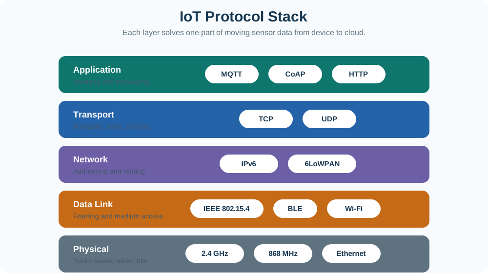
Inspect Figure 5.1 before this decision: IoT Protocol Stack must be judged beside Application. Together IoT Protocol Stack and Application bound this claim.

Layered IoT protocol stack from physical links to data link, network, transport, and application protocols.
Figure 5.1: A protocol stack is a set of layer agreements, not a single product choice.

IoT Protocol Stack begins the diagram in Figure 5.1; locate IoT Protocol Stack, compare Application, and verify Meaning and messaging. IoT Protocol Stack states the starting condition; Application supplies its counterpart; Meaning and messaging limits the conclusion; retain its labelled boundary.

Application

Defines message meaning: telemetry fields, commands, topics, resources, payload format, idempotency, and response expectations.

Transport

Defines delivery behavior: ports, streams, ordering, acknowledgements, congestion behavior, and when the application must handle loss itself.

Network and Adaptation

Defines addressing, routing, path scope, compression, fragmentation, and gateway boundaries for constrained links.

Link and Physical

Defines frame size, medium access, radio band or wire, reachability, duty cycle, interference, retries, and local diagnostics.

Review rule:

Do not compare MQTT, IPv6, Wi-Fi, and LoRaWAN as if they all solve the same problem. First identify the layer responsibility, then ask whether that layer's behavior fits the device and deployment.

5.3 Practitioner: Select the Stack from Constraints

Protocol selection should start with the system behavior, not a favorite protocol name. A practitioner asks what the device must send, how often, how far, under what power budget, through which gateway or service, and with what failure behavior.

The result is a short stack record: application protocol, payload format, transport behavior, network or adaptation layer, link technology, security wrapper, gateway handoff, and the evidence that proves the choices fit.
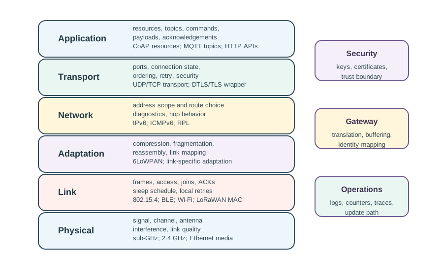
The next claim about practitioner: select the stack from constraints depends on Figure 5.2. Its diagram makes Application and resources, topics, commands explicit within choose each layer for a reason and record the handoff between layers.

Protocol stack architecture layer map showing application, transport, network and adaptation, link, and physical responsibilities.
Figure 5.2: Choose each layer for a reason and record the handoff between layers.

Compare Application with resources, topics, commands inside the visual at Figure 5.2. Next find payloads, acknowledgements, which completes the scope of choose each layer for a reason and record the handoff between layers. The decision in practitioner: select the stack from constraints must preserve that labelled boundary.

Selection Flow

1. Message meaning

Name telemetry fields, commands, payload format, topic or resource path, and receiver expectation.

2. Delivery behavior

Decide whether loss, duplicates, ordering, stale data, retries, and acknowledgements are handled by the app, transport, or link.

3. Path and gateway

Identify addressing scope, routing, compression, fragmentation, translation, buffering, and identity mapping.

4. Medium fit

Check range, power, channel sharing, mobility, installation environment, interference, and diagnostics.

5. Evidence gate

Keep traces, packet sizes, loss behavior, coverage notes, power observations, and owners for unresolved risk.

Scenario Signal
Stack Pressure
Weak Review
Evidence to Keep
Sparse battery telemetry
Small payloads, long sleep time, minimal radio airtime, and tolerant freshness rules.
Choosing a verbose web stack because it is familiar.
Payload ledger, retry rule, coverage check, battery observation, and receiver stale-data behavior.
Operator commands
Clear acknowledgement, authorization, timeout, duplicate handling, and rollback behavior.
Assuming a dashboard click means the device changed state.
Command id, approval path, transport behavior, device acknowledgement, and final observation.
Gateway translation
Identity, timestamp, quality, buffer, protocol mapping, and ownership across both sides of the gateway.
Treating the gateway as an invisible cable.
Mapping table, timestamp policy, loss policy, credential owner, and monitoring owner.
High-rate media or diagnostics
Throughput, latency, congestion behavior, power source, storage, and backhaul capacity.
Using a low-power telemetry link for traffic it cannot carry.
Rate measurements, congestion test, storage plan, and backhaul evidence.

5.4 Under the Hood: Boundaries Create Failure Modes

The hard part of a protocol stack is often not the protocol syntax. It is the boundary behavior: where payloads are wrapped, where reliability is added, where packets are compressed or fragmented, where identity changes, and where operators can see failure.

Under the hood, every layer adds context and cost. Headers, acknowledgements, retransmissions, security wrappers, and gateway buffers are useful when they serve the requirement; they are waste when they hide responsibility or exceed the link budget.
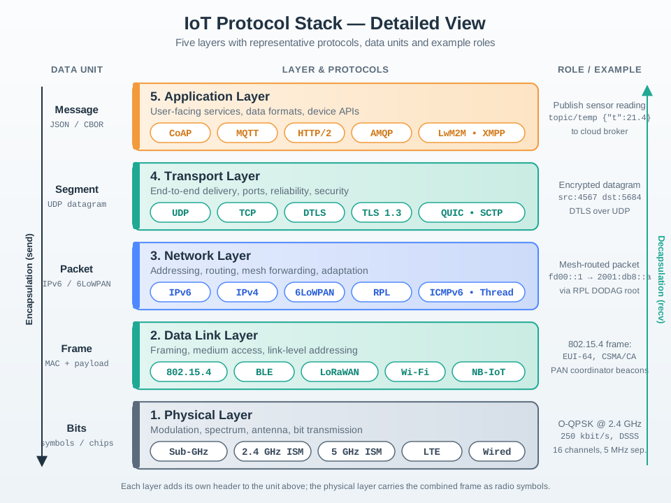
Before under the hood: boundaries create failure modes, inspect Figure 5.3: IoT Protocol Stack — Detailed View must be considered with DATA UNIT. That visual pairing grounds layer-aware review asks what each boundary adds, removes, preserves, or translates in named evidence.

Detailed IoT protocol stack across five layers, each with representative protocols, data units, and example roles: application with CoAP, MQTT, HTTP/2, and AMQP; transport with UDP, TCP, DTLS, TLS, and QUIC; network with IPv6 addressing and routing; data link; and physical.
Figure 5.3: Layer-aware review asks what each boundary adds, removes, preserves, or translates.

Trace the visual from IoT Protocol Stack — Detailed View to DATA UNIT in Figure 5.3; verify LAYER & PROTOCOLS before concluding. Together those labels make layer-aware review asks what each boundary adds, removes, preserves, or translates testable. Apply their boundary when working through under the hood: boundaries create failure modes.

Boundary Evidence Record

Boundary
What Can Go Wrong
Evidence Needed
Review Question
Application to transport
The message looks delivered, but command meaning, duplicate handling, or freshness is unclear.
Payload schema, topic or resource path, idempotency rule, acknowledgement rule, and retry owner.
Who decides whether a message is safe to retry?
Transport to network
Reliability assumptions break when paths are lossy, sleepy, buffered, or translated.
Connection model, ordering expectation, duplicate handling, security wrapper, route, and fragmentation risk.
Does reliability belong to the app, transport, constrained network, or gateway?
Network to link
Address mapping, compression, fragmentation, or retries hide where packets are actually dropped.
Address plan, adaptation context, frame fit, link acknowledgement, retry count, and channel evidence.
Can the chosen link carry the packets without fragile fragmentation?
Gateway to cloud
Translation changes identity, time, quality, credentials, or failure visibility.
Identity mapping, timestamp source, buffer policy, stale marker, credential owner, and monitoring owner.
Can another engineer audit what the gateway changed?
Common pitfall:

A protocol family name is not a deployed contract. Check the exact profile, feature set, security mode, payload limits, gateway behavior, and operational owner before treating two devices or services as interoperable.

Protocol Stack Review Checklist

Begin with the physical event, payload, receiver, and action the stack supports. Record the payload size and the effect of headers, security, retries, and fragmentation on the constrained link. Then identify where loss, duplicate messages, ordering, stale data, and command confirmation are handled, followed by every gateway or bridge that changes identity, timestamp, topic, path, credential, or quality marker. Keep packet traces, coverage evidence, power observations, and monitoring ownership with that decision record.

The tilt-maze example is a round trip, not a one-way stack. Figure 5.4 follows a +12 degree tablet sample to the actuator and then brings video evidence back.

Five-stage sequence: tablet sensor API maps orientation to RIGHT; Wi-Fi or mobile access carries an IP and TLS packet; Raspberry Pi bridges to a 62 degree servo command; Arduino produces PWM; camera returns RTP or WebRTC video.
Figure 5.4: End-to-end protocol sequence for an Internet-connected tilt maze from tablet orientation through Raspberry Pi and Arduino control to return video.

At TABLET, Figure 5.4 maps θx=+12° to RIGHT and sequence 184; GATEWAY then translates that intent into servo 62° before ARDUINO produces PWM. The RETURN card closes the control loop with camera video, proving why application, transport, Internet, bridge, and local-control transitions must all be named.

5.5 Worked End-to-End Stack Trace: Connected Tilt Maze

Consider a tablet that steers a physical maze while receiving video of the ball. It carries two flows with different timing needs: a small orientation command travels toward the maze, while a sustained video stream travels back. Trace them separately.

StepData at this pointBoundary crossedUseful evidence
1Pitch and roll samples from the tablet IMUPhysical motion to sensor register to mobile applicationSample rate, axis convention, calibration, timestamp
2A bounded steering commandApplication serialization and session policyUnits, range check, sequence number, send time
3Transport segment or datagram inside IPApplication to transport and Internet layersPorts, loss/retry policy, IP endpoints
4Wi-Fi or cellular link frameIP to the tablet’s current access networkAssociation or bearer, retries, signal evidence
5Routed IP packetAccess network through Internet routersRoute, latency, loss, NAT/session state where present
6Command received by Raspberry Pi processNetwork stack back to applicationReceive time, sequence gap, stale-command rejection
7Local Arduino commandGateway translation onto USB serial, UART, I2C, SPI, or another local linkFraming, baud or clock, checksum, acknowledgement
8Motor position changeControl output through driver to actuatorSetpoint, limit, saturation, physical acknowledgement
9Camera frames encoded by the PiPhysical light to camera, encoder, and return streamFrame time, codec queue, bitrate, dropped frames
10Video decoded on tabletReverse network path and application renderingEnd-to-end glass-to-glass latency and jitter

The command crosses the stack more than once because the Raspberry Pi is both an Internet endpoint and a local gateway. It decapsulates the Internet message all the way to its control application, validates freshness and limits, then creates a new local-link message for the Arduino. This is not IP forwarding unless the Arduino itself participates in that IP network; it is application-level translation between two protocol domains.

The video follows a separate pipeline. Camera exposure and frame readout precede encoding, network queueing, transport, decoding, and display. A fast command round trip does not prove low video latency, and smooth video does not prove that a stale motor command will be rejected. Give each flow its own sequence number, timestamps, timeout, and failure behavior.

Work one command numerically. Suppose sensing and serialization take 12 ms, access and Internet delivery take 48 ms, Pi validation takes 3 ms, the local Arduino handoff takes 7 ms, and motor response begins after 15 ms. The command-to-motion latency is

Tcontrol=12+48+3+7+15=85 ms.T_{\text{control}}=12+48+3+7+15=85\ \text{ms}.

If a packet arrives 300 ms late after a radio retry, the correct action may be to discard it rather than move the maze toward an obsolete orientation. Layering makes delivery possible; application semantics decide whether delivered data is still safe to use.

5.6 IoT Reference Models

5.6.1 Start With the IoT System, Not the Diagram

Map One Alarm Across Every Owner

Picture a freezer alarm moving from a probe to a local controller, across a network, into a service, and finally to a technician. A layer picture helps only when each hand-off has an owner and evidence.

OSI means Open Systems Interconnection, a model that separates network communication jobs. A protocol is a shared set of rules for exchanging data. TCP means a connected byte stream that tracks order and loss. Telemetry means measurements and status sent from remote devices for review.

Trace one alarm with its source identity, time, unit, quality flag, and version. Break a hand-off, delay it, repeat it, restart one part, and keep the local safe response available. Record where the evidence stops rather than calling a reachable service operationally ready.

This runway does not choose products or prove the full system. The deeper sections compare network models with IoT responsibility models and show how device, service, security, management, and human action fit together.

An IoT reference model is not a poster to memorize. It is a way to keep device hardware, connectivity, edge processing, platforms, applications, people, and governance from being mixed together in one vague architecture box.

Follow one real telemetry or control path through the model. Each layer should explain a responsibility, an owner, and the evidence needed to know the system is still doing its job.

5.6.2 Overview: Reference Models Name the Jobs

OSI and TCP/IP explain how network messages are packaged, addressed, routed, and delivered. IoT reference models add a different lens: they name the functional jobs around the network path, including devices, gateways, edge processing, service support, applications, management, security, and operational decisions.

That extra lens matters because an IoT system is rarely just one device talking to one server. It may include constrained sensors, actuators, non-IP radios, gateways, brokers, local filtering, data stores, dashboards, fleet management, firmware updates, and human response workflows. A reference model gives reviewers a shared map for asking whether each responsibility has an owner and evidence trail.

For example, a cold-chain monitor may start with a calibrated temperature tag, pass through a BLE gateway in a truck, use cellular backhaul, land in a message broker, update a shipment record, and trigger a driver alert. OSI and TCP/IP help debug the radio link, IP route, TLS session, or MQTT exchange. The IoT reference model asks the surrounding questions: who proves the tag was calibrated, who owns gateway buffering during dead zones, which service normalizes units, what security evidence follows the reading, and which operations workflow acts on the alarm. That prevents a review from treating a successful packet trace as proof that the deployment is operationally ready, and exposes missing ownership before procurement locks in.

If you only need the intuition, remember this: OSI and TCP/IP explain communication mechanics; IoT reference models explain deployment responsibilities. A useful architecture review needs both.

The next claim about overview: reference models name the jobs depends on Figure 5.5. Its diagram makes ITU IoT Reference Model and L4 explicit within the itu view keeps the model compact: devices generate or act on physical-world data, networks carry it, service support prepares it, and.

ITU IoT reference model with device, network, service support, and application layers plus management and security capabilities
Figure 5.5: The ITU view keeps the model compact: devices generate or act on physical-world data, networks carry it, service support prepares it, and applications use it. Management and security cut across the stack.

At ITU IoT Reference Model in Figure 5.5, compare the diagram with L4; then locate Application. That labelled check bounds the itu view keeps the model compact: devices generate or act on physical-world data, networks carry it, service support prepares it, and. For overview: reference models name the jobs, retain Application as evidence for the resulting choice.

The Four Questions

What touches the world?

Identify the sensors, actuators, controllers, tags, and gateways that create or apply physical-world information.

What moves the data?

Name the local links, wide-area links, addressing, routing, and gateway translation that let data cross boundaries.

What makes it usable?

Locate filtering, normalization, storage, identity mapping, event handling, and APIs that turn readings into usable records.

What drives action?

Connect dashboards, controls, alerts, maintenance workflows, compliance records, and business decisions to the data path.

Overview Knowledge Check

If this is enough, you can stop here: use IoT reference models to check whether the system has clear owners for the device path, network path, service path, application path, and cross-cutting controls. Continue to Practitioner when you need to map a real deployment.

5.6.3 Practitioner: Map One Deployment Before Choosing Technology

The practical use of an IoT reference model is not to decorate an architecture slide. It is to force a reviewable mapping before the team locks in radios, gateways, brokers, databases, or dashboards.

Start with one representative message: a reading, alarm, command, firmware status, or device-health event. Follow it from the physical endpoint to the decision it supports. At each layer, write down the responsibility, the evidence you expect to collect, and the owner who will maintain it.

Before choosing products, inspect Figure 5.6 to separate the responsibilities one representative message crosses. The expanded model is useful here because it prevents connectivity, processing, storage, applications, and operational work from being hidden inside one platform box.

Seven-level IoT reference model from physical devices through collaboration and processes.
Figure 5.6: Seven-level IoT reference model from physical devices to collaboration and processes

Read Figure 5.6 upward from physical devices through connectivity and edge processing, then follow data accumulation and abstraction into applications, collaboration, and processes. At each level, name the owner and evidence for the representative message rather than assigning a product by habit. The ordered map connects technology selection to the deployment decision the message supports and exposes which failure boundaries still lack proof.

A Review Map for One Message

Model Area
Responsibility
Evidence to Capture
Common Mistake
Device
Measure, identify, actuate, and expose health or state.
Device identity, calibration status, timestamp source, firmware version, and local fault state.
Treating a reading as trustworthy without knowing which device produced it.
Connectivity
Move messages across local and wide-area links, including gateway translation when needed.
Link state, retries, route, protocol boundary, gateway logs, and delivery acknowledgement.
Calling a radio choice the whole architecture.
Edge Processing
Filter, validate, transform, summarize, or trigger near the source when local action is required.
Rule version, discarded-event policy, local decision log, and fallback behavior during upstream outage.
Sending every raw event upstream without deciding what must be local.
Data Services
Persist, normalize, join, index, and expose data for applications and review.
Schema, retention policy, identity mapping, data-quality checks, and API contract.
Letting each application invent its own meaning for the same reading.
Application and Process
Turn information into monitoring, control, alerts, reports, and human or automated action.
Dashboard freshness, authorization, alert routing, action log, and escalation outcome.
Stopping at a chart without proving what decision it supports.

Practitioner Workflow

Choose a representative event that matters operationally, such as an alarm, command, health report, or compliance record. Map it first to OSI or TCP/IP for packet mechanics, then to the IoT reference model for functional responsibilities. Mark every point where its format, ownership, trust level, timing, or storage state changes. At each boundary, name the log, acknowledgement, timestamp, identity, or policy that proves correct behavior. Finish by testing the offline-device, full-gateway, unavailable-service, stale-data, and ignored-alert cases.

A Named Precedent: the M2M Service Platform

Machine-to-Machine (M2M) communication is a direct ancestor of today's IoT reference models, and it is worth naming because it already solved the same separation problem under different labels. M2M is device communication with no human step in the loop: sense, move the data across a network, extract and process the information, then act. Unlike SCADA, which was built for one isolated proprietary system, M2M assumed the device, network, and application would come from different vendors and still have to interoperate — the same cross-platform assumption an IoT reference model makes today.

The M2M Service Platform split that responsibility into four planes above a shared core network: a device plane for profile, registration, and authentication of each node; a user plane for accounts and access control; an application plane that merges device data into new services; and an access plane for the app or web delivery surface. That maps directly onto this chapter's Device, Data Services, and Application rows above — different names, the same boundaries, plus an explicit connectivity concept of its own: the M2M area network linking devices back to the platform.

M2M Node Classes: Capability Sets a Deployment Choice

M2M literature also grouped devices into node classes by capability rather than by protocol, a habit worth reusing whenever a review needs to say what a device can and cannot promise:

Low-end

Cheap, static, resource-constrained, with no IP support. Deployed at high density for basic sensing, local aggregation, and power saving.

Mid-end

Fewer constraints and may be mobile, with room for localization, quality-of-service handling, and TCP/IP support. Typical for home networks, asset tracking, and industrial automation.

High-end

Low-density, mobile, and multimedia-capable with real quality-of-service needs — a smartphone is the reference example. Typical for transport and bio-medical applications.

The M2M area network connecting those nodes back to the platform needed its own named requirements: fault tolerance, scalability, low cost and complexity, energy efficiency, dynamic configuration, minimized management traffic, and behavior that adapts to whether the traffic is data-centric, emergency, or real-time. Those are the same properties a Connectivity boundary review should still ask for today.

Use the ITU-style view when...

You need a compact teaching, procurement, or governance map that separates device, network, service support, application, management, and security responsibilities.

Use the seven-level view when...

You need to review gateway logic, edge decisions, storage, abstraction, dashboards, and people/process workflows as separate design concerns.

Use OSI or TCP/IP when...

You need to debug encapsulation, addressing, routing, transport behavior, application ports, or a protocol trace.

Use the M2M service-platform view when...

You need to separate device, user, application, and access responsibilities in a multi-vendor deployment, or classify devices by capability rather than by protocol.

Practitioner Knowledge Check

The practitioner outcome is a short review record: one representative event, the layers it crosses, the boundary changes, the evidence collected, and the failure paths that still need design work.

5.6.4 Under the Hood: Models Are Contracts, Not Stacks of Products

The most common mistake is to read a reference model as if each layer must be a separate box, product, team, or protocol. In real IoT systems, one gateway may cover several responsibilities, one cloud platform may combine storage and application functions, and one security control may need evidence at many points.

That flexibility is useful only if the architecture names the boundaries. A reference model becomes valuable when it turns an ambiguous system into contracts: what each function accepts, what it emits, which trust assumptions it makes, and what proof it leaves behind.

Consider a gateway that receives LoRaWAN payloads, rejects frames that fail integrity checks, converts raw counts into engineering units, buffers readings during backhaul loss, and forwards alarms ahead of routine telemetry. Calling it "the gateway layer" is too vague. The review should split its contracts: the radio-facing side accepts device identity, frame counters, and link metadata; the processing side emits validated records with units and timestamps; the northbound side promises retry behavior, priority ordering, and error vocabulary that downstream services can rely on.

Those contracts also explain why security and management cannot be drawn as one box at the edge of the diagram. Device identity, firmware state, key rotation, clock quality, queue depth, schema version, and alert ownership all cross layer labels. A useful model therefore records where each claim is checked, which log or test proves it, and what design change forces the review to reopen. For a release gate, the model is useful only when those records can be tested against a real message path.

To turn the model into release evidence, inspect Figure 5.7 before treating a layer label as a complete contract. The diagram shows which questions must be answered where data or control crosses between responsibilities.

Reference model boundary record with evidence, contract, owner, test, and recheck fields across device-connectivity, connectivity-edge, and edge-data-application boundaries.
Figure 5.7: Reference-model boundary record across device, connectivity, edge, data, and application responsibilities

Read Figure 5.7 across the device-to-connectivity, connectivity-to-edge, and edge-to-data-and-application boundaries. For each crossing, pair accepted fields and trust assumptions with an owner, normal test, retained evidence, and recheck trigger. That sequence turns a flexible deployment—where one gateway may implement several roles—into explicit contracts. It connects the reference model to the release gate without requiring every layer to become a separate product.

Boundary Contracts

Format Boundary

When payloads become records, events, or API objects, the contract should define fields, units, timestamps, identity, and validation behavior.

Trust Boundary

When data crosses device, gateway, tenant, cloud, or application boundaries, the contract should define authentication, authorization, integrity, and audit evidence.

Timing Boundary

When real-time events become stored data or human-facing alerts, the contract should define freshness, ordering, retry, deduplication, and stale-data handling.

Action Boundary

When information triggers an actuator, ticket, report, or escalation, the contract should define who can act, what is logged, and how rollback or override works.

How the Models Fit Together

Use OSI and TCP/IP when tracing protocol mechanics: headers, addresses, ports, routes, sessions, transport behavior, and application exchanges. Move to a compact IoT model when the task is to communicate broad responsibilities across product, operations, security, and procurement. Use an expanded IoT model when edge decisions, stored data, abstraction, applications, and people or process outcomes must be separated. Across all three views, keep security and management visible along the whole path; identity, keys, updates, monitoring, logging, and access control do not belong to only one layer.

A strong design review can point to any important reading or command and answer four questions: where did it come from, where did it change, who trusted it, and what action did it support?

Under-the-Hood Knowledge Check

The under-the-hood rule is simple: do not ask which product belongs to which layer first. Ask which responsibility, boundary, and evidence contract the design must preserve.

5.6.5 Summary

IoT reference models help teams review responsibilities that sit around the packet path. They show where devices, networks, gateways, edge processing, data services, applications, management, security, and operational workflows need clear ownership.

Use OSI and TCP/IP when you need to reason about communication mechanics. Use compact IoT models when you need a shared architecture map. Use expanded IoT models when you need to review edge logic, storage, abstraction, applications, and human or automated action.

5.6.6 Key Takeaway

An IoT reference model is not a product stack. It is a review tool for assigning responsibilities, finding boundaries, and proving that important readings and commands remain trustworthy from device to decision.

5.6.7 See Also

OSI and TCP/IP Models

OSI and TCP/IP Models

Encapsulation and Protocol Data Units

Encapsulation and Protocol Data Units

Networking Protocols and Responsibilities

Networking Protocols and Responsibilities

Datagrams and Packet Review

Datagrams and Packet Review

5.7 Summary

  • Name the physical event, payload, receiver, and action the stack supports.
  • Record payload size and how headers, security, retries, and fragmentation affect the constrained link.
  • Decide where loss, duplicate messages, ordering, stale data, and command confirmation are handled.
  • Identify every gateway or bridge that changes identity, timestamp, topic, path, credential, or quality marker.
  • Keep packet traces, coverage evidence, power observations, and monitoring ownership with the decision record.
  • IoT communication is a stack of agreements, not one protocol name.
  • Application, transport, network/adaptation, link, and physical layers each carry a different responsibility.
  • Protocol selection should start from payload meaning, freshness, delivery behavior, range, power, gateway handoff, and operational ownership.
  • Header overhead, retransmissions, security wrappers, and fragmentation are design costs that should be visible in the decision record.
  • Gateways are protocol boundaries: they need evidence for identity, timestamps, quality, buffering, credentials, and monitoring.

5.8 Key Takeaway

Choose IoT protocol stacks by matching each layer to a real constraint and recording the handoffs. A stack is credible when another engineer can see what each layer proves, what it hides, and who owns the failure cases.

5.9 See Also