38 Choosing the Right Network Type
38.1 Start With the Deployment Shape
Choosing a network type is easier when the deployment shape is clear. Is the device on the same board, across a cabinet, inside a building, across a campus, underground, mobile, or battery-powered in the field?
This chapter turns that shape into a selection record. Range, rate, energy, reliability, ownership, installation effort, and troubleshooting evidence decide whether a short wired bus, Ethernet, Wi-Fi, LPWAN, cellular, or a mix is the right fit.
Overview: Classify The Requirement, Not The Brand
Network classification is a shortcut for reasoning about reach, bandwidth, power, ownership, mobility, and failure boundaries. PAN, LAN, WAN, and LPWAN labels are useful only after the deployment requirement is bounded. A wearable badge, a PoE camera, a campus gateway, and a field soil sensor may all belong to one IoT system, but they should not use one network class.
The first decision is the communication job: how far the device must reach, how much data it sends, how often it wakes, whether it moves, who owns the infrastructure, and what happens when coverage is weak.
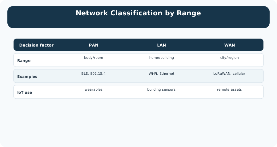
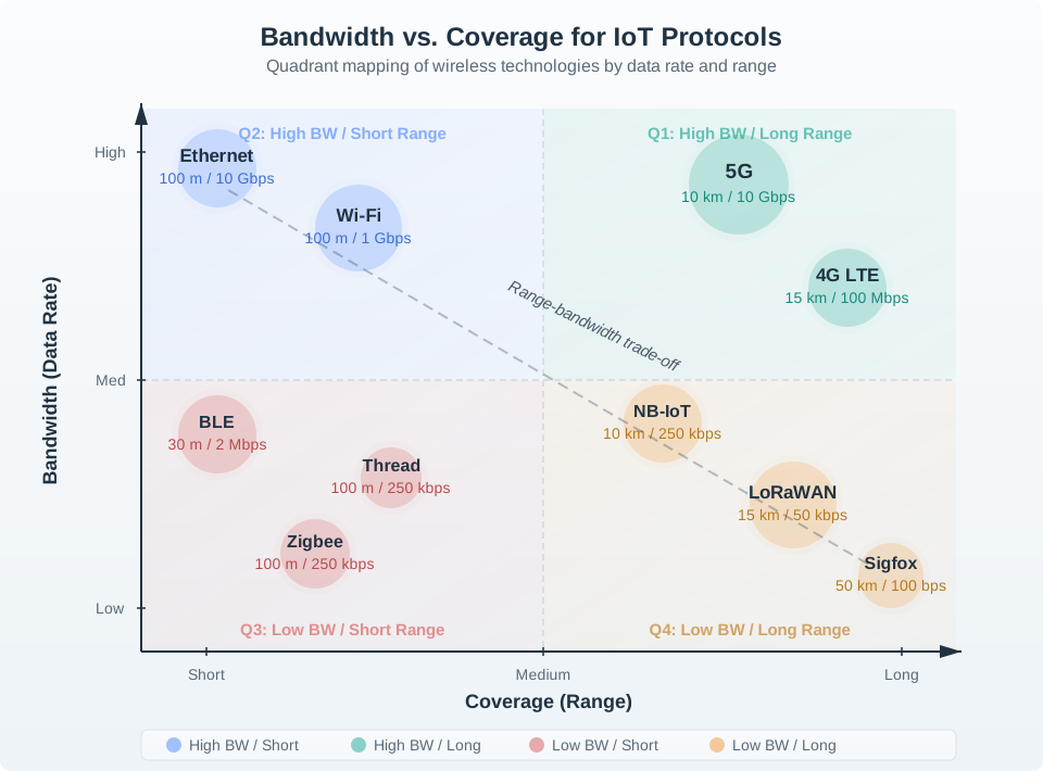
A class label is therefore an engineering filter, not a product category. PAN usually means the device can live close to a phone, reader, hub, or coordinator; LAN usually means the site can provide local infrastructure such as access points, switches, cabling, and power; WAN usually means the device or gateway must cross wider geography, operator networks, or remote backhaul; LPWAN narrows that wide-area problem for small payloads and long battery life. The useful question is not "which technology is best?" but "which class leaves the fewest unresolved assumptions for this device job?" A fixed camera, for example, may prefer Ethernet and PoE because power and predictable capacity matter more than mobility. A soil sensor may prefer LPWAN because reach and sleep time matter more than throughput. A wearable badge may prefer a PAN path because local readers keep the radio and battery budget small.
PAN
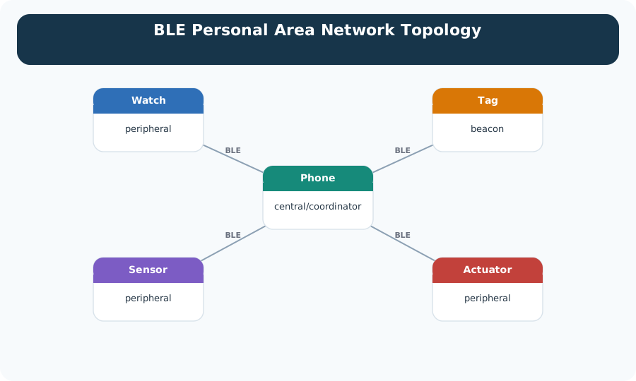
Personal-area networks fit device-local traffic: wearables, tags, room sensors, and low-power mesh nodes. The usual question is how the PAN crosses into the rest of the system through a phone, hub, router, or gateway.
LAN
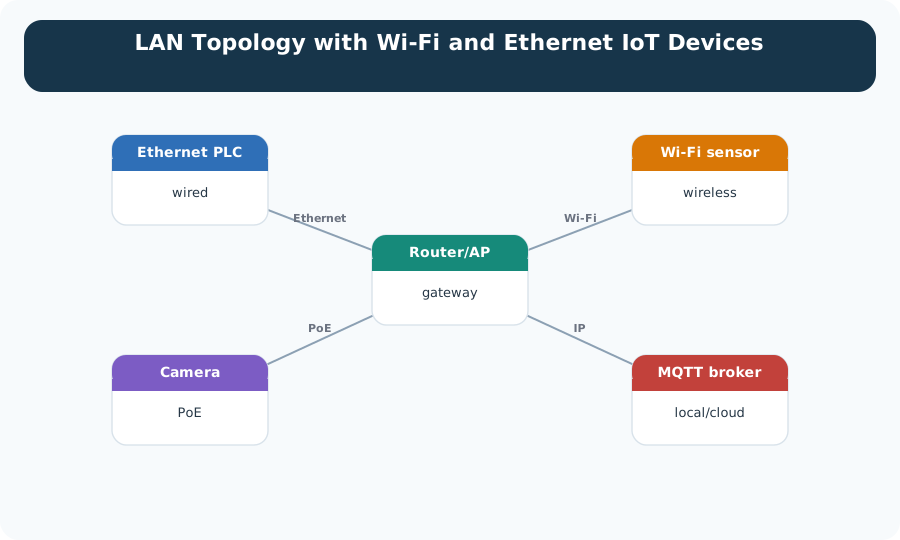
Local-area networks fit buildings and campuses. Wi-Fi and Ethernet can move more data than low-power radios, but they need access-point, switch, power, and coverage planning.
WAN And LPWAN
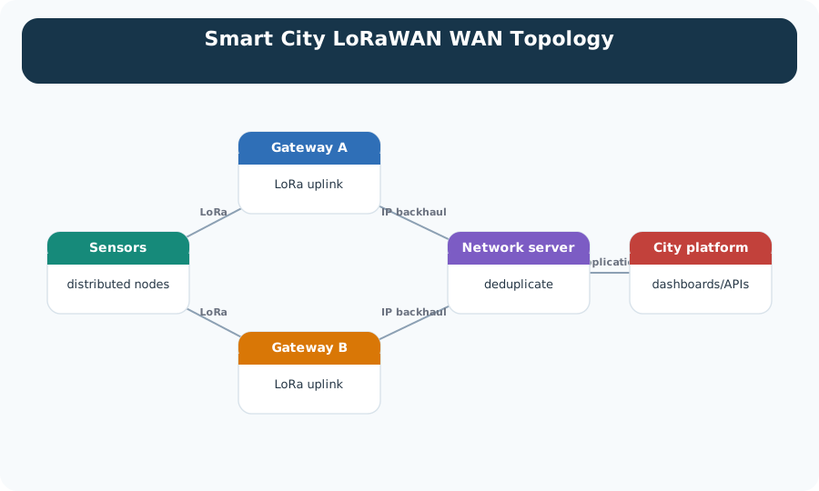
Wide-area options fit city, rural, mobile, or operator-backed deployments. LPWAN narrows the WAN problem for small, infrequent payloads and battery devices.
Classification doctrine: choose the smallest network class that can meet the range, data, mobility, power, ownership, and reliability requirement with measured margin. Do not pay for WAN behavior when a LAN or PAN gateway path is enough.
Practitioner: Build A Classification Record
A useful network classification record is a small design artifact. It does not just say "use Wi-Fi" or "use LoRaWAN." It records the tier, the reason that tier fits, the boundary where traffic moves to another tier, and the evidence that proves the choice under real conditions.
Write the record so another engineer can challenge it. For each device type, name the class, the next boundary, the normal payload, the peak payload, the wake or mobility pattern, the owner of the infrastructure, and the field test that would falsify the choice. If a badge depends on doorway readers, the reader density is part of the classification record. If a camera depends on PoE, switch power and uplink capacity are part of the record. If a remote meter depends on an operator network, coverage evidence and subscription lifecycle are part of the record.
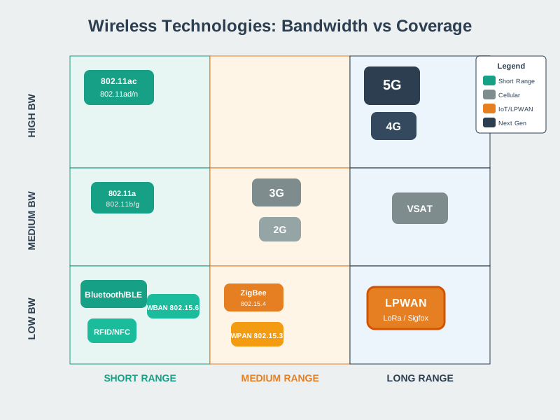
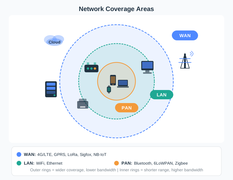
A single system can legitimately use several classes: PAN for local sensors, LAN for gateways and cameras, WAN or LPWAN for remote sites and mobile assets. The mistake is forcing all devices into one class for diagram neatness.
Under The Hood: Each Class Hides A Boundary
Classification is not a protocol stack. It is a boundary model. A PAN device still needs local addressing, pairing, channel access, and a bridge to wider services. A LAN device still needs switch or access-point capacity, power, VLAN or security policy, and backhaul. A WAN device still depends on gateway density, operator coverage, spectrum rules, provisioning, and lifecycle continuity.
The hidden work is usually translation and ownership. A short-range device may speak Bluetooth LE, Zigbee, Thread, or another local protocol, but the enterprise system often expects IP topics, HTTP APIs, MQTT messages, or database records. The phone, hub, border router, or gateway that performs that handoff changes addressing, trust, timing, retry behavior, and failure visibility. When that boundary is not recorded, teams blame the "network class" even though the real problem is a pairing policy, gateway queue, credential rotation, backhaul outage, or missing device-to-cloud mapping.
The same pattern appears in LAN and WAN choices. Ethernet can remove radio uncertainty, but it introduces cable plant, PoE budget, switch-port, VLAN, and maintenance boundaries. Wi-Fi can reuse building infrastructure, but access-point placement, channel planning, roaming behavior, and client density decide whether the class is actually adequate. Cellular and LPWAN can reach remote assets, but SIM provisioning, roaming policy, regional spectrum rules, gateway density, payload limits, and operator lifecycle become design dependencies. The classification is credible only when those dependencies are visible and testable, so boundary review becomes part of the architecture rather than a note for later.
Gateway Boundary
When a PAN or LPWAN device crosses into IP services, the gateway becomes part of the reliability and security design. Record who owns it and how it fails.
Capacity Boundary
A class can be correct while a deployment is still overloaded. Check airtime, channel use, switch capacity, retry rate, and queue growth.
Lifecycle Boundary
Operator sunsets, spectrum rules, battery replacement, gateway firmware, SIM logistics, and access-point refresh cycles can change the best class over time.

Phoebe’s Why
A battery’s nameplate rating is a charge budget, not an energy guarantee, because delivered energy depends on the (nearly constant) terminal voltage, and that voltage sags under load by an amount set by the cell’s own internal resistance – the same physics for a coin cell and a car battery, just different resistances. Two slow leaks shrink the usable share of that budget further: self-discharge quietly drains capacity even with no load at all, and a design margin has to be reserved so the device stops working cleanly at a safe cutoff voltage rather than limping along erratically. For a radio device, this budget is not independent of the RF path: a weaker, more attenuated link (the “range versus throughput” trade this chapter is built around) forces a longer, more robust transmission to be heard at all – and every extra millisecond on air is drawn straight from the same battery.
The Derivation
Charge and delivered energy, related through terminal voltage:
\[E\,\mathrm{(Wh)} = C\,\mathrm{(Ah)}\times V\]
Load sag from internal resistance:
\[V_{load} = V_{oc} - IR_{int}\]
Usable capacity after self-discharge over time \(t\) and a design derating margin \(\delta\):
\[C_{usable} = C_0\,(1-k)^{t}\,(1-\delta)\]
For an LPWAN radio, weaker RF paths are answered by more robust (slower) modulation. In LoRa, symbol duration scales directly with spreading factor:
\[T_{sym} = \frac{2^{SF}}{BW}\]
so moving to a more robust spreading factor to survive a worse path multiplies on-air time – and transmit energy – by the same factor.
Worked Numbers: A Battery LPWAN Soil Sensor
The chapter’s own example – “a soil sensor may prefer LPWAN because reach and sleep time matter more than throughput” – does not fix a cell or chemistry, so take a standard, catalog-typical LPWAN sensor cell: an ER14505 lithium-thionyl-chloride AA cell (\(V=3.6\) V, \(C_0 = 2400\) mAh).
- Energy: \(E = 2400\times3.6/1000 = 8.64\) Wh.
- Usable charge after a standard 0.7%/year self-discharge over a 5-year field life and a 15% derating margin: \(C_{usable} = 2400\times(0.993)^5\times0.85 = 1970\) mAh – 82.1% of the nameplate rating survives to do useful work.
- RF-to-energy coupling: moving from SF7 to SF12 to close a weaker path multiplies LoRa symbol time (and transmit energy per uplink) by \(2^{12-7} = 2^5 = \mathbf{32\times}\). A gateway boundary or antenna choice that forces a higher spreading factor is therefore not just a coverage decision – it is a 32x tax on the same fixed 1970 mAh budget per uplink sent at the worse setting.
That coupling is exactly why the chapter insists the classification record capture “reach, rate, energy” together: a longer LPWAN range bought with a higher spreading factor can quietly erase far more battery life than the mAh rating alone would suggest.
38.2 Summary
Network classification turns a device requirement into a defensible communication tier. PAN, LAN, WAN, and LPWAN labels help organize choices, but they do not replace engineering evidence. A strong classification record captures reach, traffic, power, mobility, topology, gateway boundaries, ownership, and field proof. Most real IoT systems mix classes: short-range devices collect data locally, LANs aggregate or carry high-bandwidth building traffic, and WAN or LPWAN links connect remote sites and mobile assets.
38.3 Key Takeaway
Choose the smallest network class that satisfies the measured requirement, and record the boundary where that class hands traffic to the next tier.
38.4 See Also
Wide-Area Access: LPWAN and Cellular
Compare low-power wide-area and cellular options after the classification points to WAN-scale reach.
Wireless Access: Wi-Fi
Use Wi-Fi when local coverage, bandwidth, and power assumptions fit the LAN side of the record.
Wired Access: Ethernet
Use Ethernet and PoE when fixed devices need predictable bandwidth, power, and operational control.
Link Budget and Coverage Planning
Convert wireless classification assumptions into received-power, margin, and field-validation evidence.