Ethernet gives IoT systems a physical path with visible link state, negotiated speed, switch ports, and often power delivery. That makes it a strong choice when reliability, serviceability, and predictable capacity matter more than cable-free installation.
Use the chapter as a deployment checklist. The story is not just “plug in a cable”; it is proving cable length, PoE budget, duplex and speed negotiation, switch path, and what happens when the device must share the network.
Packet Pete
“A cable is a promise with a length limit — show me the run, the port, and the record that proves it holds.”
Here Pete follows the physical link itself: the conductor, the record it needs, and the fault it can point back to.
Key Concepts
Ethernet: The dominant wired LAN standard (IEEE 802.3); defines the physical layer and MAC protocol for wired networks
PoE (Power over Ethernet): Delivering DC power alongside data over the same Ethernet cable; eliminates separate power wiring for IoT devices (cameras, access points, sensors)
CSMA/CD: The original Ethernet MAC protocol; deprecated in modern full-duplex switched Ethernet where collisions are physically impossible
Industrial Ethernet: Deterministic extensions of standard Ethernet for industrial automation (PROFINET, EtherNet/IP, EtherCAT); provides microsecond-level timing
Cat5e/Cat6 Cable: Twisted-pair Ethernet cable categories; Cat5e supports Gigabit Ethernet up to 100 m, Cat6 provides better crosstalk performance
Auto-Negotiation: The process by which two Ethernet devices agree on the highest common speed and duplex mode without manual configuration
Switched Ethernet: Modern Ethernet topology where each device has a dedicated full-duplex link to a switch port, eliminating shared medium collisions
35.2 In 60 Seconds
Ethernet (IEEE 802.3) provides the most reliable IoT connectivity with deterministic latency, no interference, and speeds from 10 Mbps to 10 Gbps over twisted-pair copper or fiber. Power over Ethernet (PoE) delivers up to 100W (IEEE 802.3bt Type 4) through the same cable, eliminating separate power wiring for IP cameras, access points, and industrial sensors. Ethernet is ideal for stationary IoT devices where reliability matters more than mobility—think factory floors, security systems, and building automation gateways.
Phoebe’s Field Notes: The 100 m Limit Is a Skin-Effect Problem, Not a Multipath One
Phoebe’s Why
A copper Ethernet cable is a guided path, not free space, so the wireless story of reflection, diffraction, and Doppler shift this estate usually tells for “why higher frequency loses more” does not apply here – there is no open-air wave bouncing off anything. The frequency penalty this chapter’s own “20 dB per 100 m at 100 MHz” number comes from is skin effect: at high frequency, current in a copper conductor crowds into a thin shell near the surface instead of using the whole cross-section, so the wire’s effective resistance rises with frequency even though its physical size never changes. That is a guided-wave, conductor-physics penalty – the honest frequency-dependent-loss mechanism for this chapter, replacing the free-space multipath story that governs the wireless chapters instead.
The Derivation
Skin depth – how far current penetrates into the conductor before it has decayed to \(1/e\) of its surface value:
\[\delta = \sqrt{\frac{\rho}{\pi f \mu_0}}\]
Because effective conducting area shrinks as \(\delta\) shrinks, AC resistance (and with it, conductor-loss attenuation) rises with the square root of frequency:
Total per-length attenuation adds a smaller, frequency-linear dielectric-loss term on top of that square-root conductor term, which is why cable attenuation curves flatten in log-log slope at high frequency rather than following a clean power law all the way up.
Worked Numbers: This Chapter’s Own Cat6 Attenuation
Skin depth in copper (\(\rho=1.68\times10^{-8}\ \Omega\cdot\)m): at \(1\) MHz, \(\delta=\sqrt{1.68\times10^{-8}/(\pi\times10^{6}\times4\pi\times10^{-7})}=65.2\ \mu\)m; at \(100\) MHz, \(\delta=6.52\ \mu\)m – a \(10.0\times\) shrink, matching \(\sqrt{100\,\mathrm{MHz}/1\,\mathrm{MHz}}=10.0\) exactly, confirming the square-root scaling.
Applying that same \(\sqrt{f}\) scaling to this chapter’s own \(19.8\) dB/100 m at 100 MHz (Cat6) predicts roughly \(19.8\times\sqrt{10/100}=6.26\) dB/100 m at 10 MHz – conductor loss dominates the low-to-mid-frequency part of the curve the chapter’s own “20 dB per 100 m” figure sits on.
At the chapter’s own 100 m limit, that \(19.8\)-\(21\) dB budget leaves little margin above the noise floor for PAM-5 decoding, which is why the standard mandates a repeater or switch every 100 m rather than letting the run continue – a hard conductor-physics wall, not a multipath one.
Learning Objectives
By the end of this section, you will be able to:
Explain the role of Ethernet (IEEE 802.3) in IoT deployments and justify when it is preferable to wireless alternatives
Compare and differentiate Ethernet standards (10BASE-T, 100BASE-T, 1000BASE-T) by speed, application, and physical layer characteristics
Select appropriate Ethernet standards for given IoT use cases based on bandwidth and latency requirements
Evaluate trade-offs between wired Ethernet and wireless connectivity for specific IoT deployment scenarios
Calculate PoE power budgets for IoT installations using IEEE 802.3af, 802.3at, and 802.3bt standards
Chapter Roadmap
Use the chapter as an Ethernet release checklist:
First identify what 10BASE-T, 100BASE-T, 1000BASE-T, cable category, and auto-negotiation prove about the link.
Then decide when wired service beats Wi-Fi for cameras, robots, and other stationary IoT devices.
Next calculate PoE budget, cable length, and switch capacity before the device is installed.
Finally turn link speed, duplex, PoE class, VLAN, route, and error counters into a deployment record.
Checkpoints recap the design decisions; calculators, quizzes, and the reliability contract provide the evidence trail.
35.3 Prerequisites
Before diving into this chapter, you should be familiar with:
Networking Basics: Understanding fundamental networking concepts including protocol layers and data transmission principles
For Beginners: What is Ethernet?
Ethernet is the most common wired networking technology. Think of Ethernet cables as highways for data - they’re fast, reliable, and can carry lots of traffic without interruption.
When you plug your computer into a router with a cable, that’s Ethernet! The cable has 8 wires inside arranged in twisted pairs that carry electrical signals representing your data.
Term
Simple Explanation
Ethernet
Wired connection using twisted-pair cables (like RJ45 “phone jack” connectors)
100BASE-T
Fast Ethernet - 100 Mbps (megabits per second)
1000BASE-T
Gigabit Ethernet - 1000 Mbps (10x faster than 100BASE-T)
PoE
Power over Ethernet - delivers both data AND electricity through one cable
“Why would anyone use wires when wireless is so convenient?” asked Sammy the Sensor. Max the Microcontroller had a quick answer. “Reliability! Ethernet never drops out because of interference, it delivers data at consistent speed, and it can even provide power through the same cable.”
“Power over Ethernet is amazing,” said Lila the LED. “A single Ethernet cable plugs into a security camera and delivers both the network connection AND up to 90 watts of power. No separate power cable needed! That is why PoE is so popular for IP cameras, Wi-Fi access points, and building sensors.”
“Ethernet also has zero radio interference,” added Bella the Battery. “In a factory with lots of motors, welders, and heavy machinery that mess up wireless signals, a wired Ethernet connection keeps working perfectly. For critical infrastructure like factory control systems and building automation gateways, wired is the way to go.”
“The trade-off is obvious though,” said Sammy. “You cannot put Ethernet cables in a farmer’s field or on a moving robot. Ethernet is perfect for STATIONARY devices where reliability matters more than mobility. Match the connection type to the job!”
35.4 IEEE 802.3 Ethernet for IoT
Time: ~8 min | Difficulty: Intermediate | Reference: P07.C11.U02
Start with the physical promise: Ethernet can be inspected. The first pass names the standards, speed choices, cable limit, and negotiation evidence you need before comparing it with wireless options.
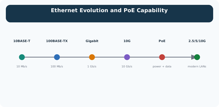
IoT devices may be connected via a wired connection. For permanent installations, Ethernet is commonly used. The data rate using Ethernet can range from 10 Mbps to more than 1 Gbps (1000 Mbps).
Figure 35.1: Evolution of Ethernet standards showing increased speeds and Power over Ethernet capabilities
35.4.1 Common Ethernet Standards
10BASE-T: 10 Mbps, found on small microcontrollers and legacy industrial equipment
100BASE-T: 100 Mbps (Fast Ethernet), common on higher-powered microcontrollers or single-board computers like Raspberry Pi
1000BASE-T: 1000 Mbps (Gigabit Ethernet), used for high-bandwidth applications like IP cameras and industrial gateways
Checkpoint: Link Identity
You now know:
10BASE-T, 100BASE-T, and 1000BASE-T describe 10 Mbps, 100 Mbps, and 1000 Mbps Ethernet links.
Cat5e supports Gigabit Ethernet up to 100 m, while Cat6 improves crosstalk performance.
Auto-negotiation can only select a speed supported by both ends of the link.
35.5 Which Speed Will The Link Negotiate?
Quiz: Matching Standards to Devices
Ethernet-Connected IoT Devices
IP Cameras: 4K video transmission. Transmitting 4K quality video over Wi-Fi may create problems due to data speed constraints
VoIP Devices: Voice over IP communications requiring consistent quality
Set-top Boxes: Video/audio streaming and storage
Game Applications and Systems: Low-latency gaming
Static Industrial Equipment: Manufacturing machinery, process control
High-Security Sensors: Transmitting via wireless is viewed as high-risk; wired preferred
High-Reliability Control: Robotics, medical applications requiring deterministic communication
35.5.1 Advantages of Ethernet for IoT
Advantage
Description
High bandwidth
10 Mbps to 10+ Gbps - supports any IoT data rate
High reliability
No radio interference, consistent performance
Low latency
Sub-millisecond latency for real-time control
Deterministic
Predictable timing (critical for industrial)
PoE capability
Single cable for data AND power
Security
Physical access required - no wireless eavesdropping
Putting Numbers to It
Ethernet’s maximum cable length is set by signal attenuation physics. Cat6 cable attenuation at 100 MHz is approximately 20 dB per 100 meters (per TIA-568-C standard).
For Gigabit Ethernet (1000BASE-T), the 100 m limit is derived from the signal-to-noise ratio needed for reliable PAM-5 decoding across four wire pairs. The IEEE 802.3 standard specifies an end-to-end channel loss budget:
\[\text{Max channel insertion loss} \approx 21 \text{ dB at } 100 \text{ MHz (Cat5e)}\]
\[\text{Cat6 attenuation at 100 MHz} \approx 19.8 \text{ dB/100m}\]
At 100 m, the received signal is close to the noise floor, leaving minimal margin. Beyond 100 m, bit error rates rise sharply and automatic repeat request (ARQ) overhead degrades throughput. A repeater or switch must be placed every 100 m to regenerate the signal.
For 10 Gbps (10GBASE-T), the more demanding modulation scheme (PAM-16) requires better SNR, which is why it is limited to 55 m on Cat6 cable and requires Cat6A (10GBASE-T is specified for 100 m only on Cat6A or Cat7).
35.5.2 Cable Construction and Deployment Evidence
Ethernet cabling is not only a connector choice. The conductor, shield, insulation, jacket rating, and route all change whether the link keeps its margin after installation. Copper is the normal data conductor because it combines low resistance, cost, and flexibility. Aluminium, steel, nickel, tin, and silver appear in specialized cable or connector contexts, but they usually represent a tradeoff: lower cost, corrosion resistance, solderability, strength, or high-frequency surface performance rather than a blanket improvement over copper.
At high frequency, current concentrates near the outside of a conductor. This skin effect is one reason cable construction, plating, and stranding matter more as data rates rise. Silver-plated copper can reduce high-frequency surface loss, tinned copper improves solderability and corrosion behavior, and nickel plating can survive harsher temperatures, but each choice must be justified against cost, bend radius, connector compatibility, and standards compliance.
For building Ethernet, the practical review is usually simpler: verify the cable category, pair twist, shield choice, and jacket rating. Twisted pairs reduce coupled noise because interference tends to affect both wires similarly, while the receiver reads the difference between them. Shielded cable can help near motors, drives, fluorescent ballasts, or radio equipment, but only when grounding and termination are planned; a badly bonded shield can become part of the noise problem. Plenum, riser, general-purpose, and low-smoke-zero-halogen jacket ratings are safety and code decisions, not performance labels. They say where a cable is allowed to run and what smoke or flame behavior is expected.
Long or harsh routes add another evidence layer. A data-center patch lead, an industrial tray cable, a marine cable, and an undersea fibre cable are all “wired links,” but their release evidence is different. Submarine systems care about water blocking, armour, repeater power, burial depth, repair access, and shore landing protection. The IoT lesson is to record the physical route beside the protocol: cable type, pathway, bend radius, shield bond, fire rating, moisture exposure, and acceptance test are part of the link contract.
Pete’s Delivery Slip
Address: copper is the default conductor for a reason – low resistance, cost, and flexibility.
Route: twisted pairs reject coupled noise by reading the difference between two wires, not by shielding alone.
Receipt: plenum, riser, and low-smoke jacket ratings are fire-code decisions, not performance labels – record them beside the protocol.
35.5.3 Disadvantages of Ethernet for IoT
Disadvantage
Description
Physical cabling
Requires cable runs to each device
Installation cost
Labor-intensive, especially retrofit
Limited mobility
Devices must be stationary
Not battery-powered
Requires mains or PoE infrastructure
Inflexible
Difficult to relocate devices
MVU: Power over Ethernet (PoE)
Core Concept: PoE delivers DC power (15-90W) alongside data over standard Ethernet cables, eliminating separate power wiring for IoT devices like IP cameras, access points, and sensors.
Why It Matters: A single cable installation reduces deployment cost by 30-50% for devices that would otherwise need both Ethernet and power outlets. PoE switches also enable centralized power management and UPS backup for all connected devices.
Key Takeaway: Use PoE (802.3af, 15.4W) or PoE+ (802.3at, 30W) for cameras, access points, sensors, and thin clients. PoE++ (802.3bt Type 3: 60W, Type 4: 100W) supports higher-power devices like PTZ cameras and small displays. Always verify both the switch and the device support the same PoE standard before deployment.
Ethernet vs Wi-Fi for 4K Video
Scenario: A warehouse needs 50 IP cameras for security. Each camera streams 4K video at 25 Mbps. The warehouse is 200m x 150m with metal shelving causing RF interference.
Given:
50 cameras, each producing 25 Mbps video stream
Total bandwidth: 50 x 25 Mbps = 1,250 Mbps (1.25 Gbps)
Distance from cameras to switches: 50-80 meters
Environment: Metal shelving, forklifts, variable lighting
Result: Insufficient - video stuttering, dropped frames
Option B: Gigabit Ethernet with PoE+
Each camera gets dedicated 1 Gbps port
25 Mbps uses only 2.5% of available bandwidth
No radio interference
PoE+ provides up to 30W power per camera
Result: Optimal - consistent 4K streaming
Cost Comparison (50 cameras):
Item
Wi-Fi
Ethernet
Infrastructure
$3,000 (6 APs)
$8,000 (2x 24-port PoE switches)
Cabling
$500 (power drops)
$5,000 (Cat6 runs)
Power outlets
$2,500 (50 outlets)
$0 (PoE)
Total
$6,000
$13,000
Reliability
Variable
Excellent
Result: Ethernet costs more upfront but provides guaranteed performance. For mission-critical surveillance, the additional $7,000 is justified by eliminating video loss during incidents.
Key Insight: The text states cameras are Ethernet examples because “Transmitting 4K quality video over Wi-Fi may create problems due to data speed constraints.” Ethernet’s deterministic performance is essential for security applications.
Checkpoint: Wired Fit
You now know:
A 50-camera warehouse at 25 Mbps per camera needs 1,250 Mbps before management overhead.
Ethernet gives each camera a dedicated 1 Gbps port; Wi-Fi shares airtime and can drop frames in metal-heavy spaces.
Robot control with a 100 ms update interval and a less-than-10 ms latency target belongs on deterministic Ethernet+TSN, not a best-effort wireless link.
Select Protocols for Robots
Scenario: A factory needs to connect 50 industrial robots across a 200m x 150m floor. Robots require telemetry every 100ms with <10ms latency and zero packet loss for safety.
Given:
50 robots with 100ms update interval
Latency requirement: <10ms
Packet loss: Zero tolerance (safety-critical)
Data per update: 500 bytes
Total bandwidth: 50 x (500 bytes x 8 / 0.1s) = 2 Mbps
Requirements Analysis:
Requirement
Wi-Fi 6
LoRaWAN
Zigbee
Ethernet+TSN
Latency
3-200ms
2500ms
60ms
0.069ms
Packet Loss
1-5%
5-10%
5-10%
0%
Deterministic
No
No
No
Yes
Bandwidth
9.6 Gbps
50 kbps
250 kbps
1 Gbps
Analysis:
The text explicitly lists “Robotics, medical applications requiring deterministic communication” as Ethernet examples, citing advantages of “Low latency and jitter” and “Deterministic performance.”
Wi-Fi: 3.7ms typical but 50-200ms worst-case spikes (non-deterministic). 1-5% packet loss unacceptable for robot safety.
LoRaWAN: 2,500ms latency is 250x too slow. Transmission time (1.45s) exceeds update interval (100ms).
Ethernet + TSN: 0.069ms latency with zero jitter. Time-Sensitive Networking guarantees bounded latency.
Result: Gigabit Ethernet with TSN (Time-Sensitive Networking) is the only viable option. TSN extensions (IEEE 802.1Qbv) provide deterministic scheduling, ensuring robot control packets are never delayed.
Key Insight: For safety-critical industrial control, only wired Ethernet can guarantee the bounded latency and zero packet loss required. Wireless protocols are fundamentally non-deterministic due to shared medium access.
35.6 Knowledge Check
Quiz: Ethernet vs Wi-Fi for 4K Video
35.7 How the PoE Budget Calculator Works
Planning a PoE deployment requires matching the switch’s total power budget to the devices it must power. The interactive calculator below is the primary learning activity; this table explains the same logic without making learners read a long code listing.
Step
What to Check
Why It Matters
1
List every powered device and its maximum wattage
The switch must survive peak draw, not just typical draw
2
Multiply each device wattage by its device count
Many small loads can exceed the switch’s total budget
3
Check each device’s PoE class against the switch port
A switch may have enough total watts but still lack PoE+ or PoE++ per-port support
4
Compare total peak draw with the switch budget
If peak draw exceeds the budget, the switch can shut down low-priority ports
5
Leave at least 20% headroom
Future devices, cold-start draw, and cable losses all need margin
Why this matters: A 48-port PoE switch might advertise 370 W total budget but support 30 W per port. If you connect 24 devices at 15 W each (360 W), the switch is near capacity and cannot support another powered device at full draw. Always calculate the aggregate budget, not just per-port limits.
PoE planning is the power version of speed negotiation: the port, switch budget, cable route, and device peak draw all have to agree at the same time.
Try It: PoE Switch Budget Calculator
Adjust the device counts to see whether your PoE switch budget is sufficient. The calculator shows peak and typical draw and flags oversubscription.
Show code
viewof switchBudget = Inputs.range([100,740], {value:370,step:10,label:"Switch PoE budget (W)"})viewof numCameras1080 = Inputs.range([0,24], {value:12,step:1,label:"1080p IP Cameras (12.5 W each)"})viewof numCamerasPTZ = Inputs.range([0,12], {value:4,step:1,label:"4K PTZ Cameras (25 W each)"})viewof numAPs = Inputs.range([0,12], {value:6,step:1,label:"Wi-Fi 6 Access Points (18 W each)"})viewof numVoIP = Inputs.range([0,40], {value:20,step:1,label:"VoIP Phones (6.5 W each)"})viewof numGateways = Inputs.range([0,10], {value:3,step:1,label:"IoT Sensor Gateways (8 W each)"})viewof numDoors = Inputs.range([0,10], {value:4,step:1,label:"Door Access Controllers (10 W each)"})
PoE, PoE+, and PoE++ map to 15.4 W, 30 W, and 60 W or 100 W service classes.
A 370 W switch budget can be consumed by many small loads; leave at least 20% headroom.
Standard 100BASE-TX and 1000BASE-T runs are limited to 100 m unless a switch, extender, or fibre path regenerates the link.
Common Pitfalls
Keep Ethernet Runs Under 100 m
Standard Ethernet (100BASE-TX, 1000BASE-T) is limited to 100 m per segment. Exceeding this causes signal degradation and high bit error rates. Fix: use a switch or Ethernet extender for runs over 100 m, or switch to fibre optic.
Check PoE Budget Before Mixing
A 24-port PoE switch may have a total power budget of 370 W. Connecting 24 devices each drawing 15.4 W (PoE) exceeds the budget by 2×. Fix: calculate total PoE load and verify it does not exceed the switch’s power budget before deployment.
Ethernet Is Not Always Reliable
Poorly terminated connectors, damaged cable jackets, or incompatible cable categories cause Ethernet errors that are harder to diagnose than RF issues. Fix: test Ethernet links with a cable tester before deployment and verify auto-negotiation is operating correctly.
Label the Diagram
Code Challenge
35.8 Ethernet Reliability Contract
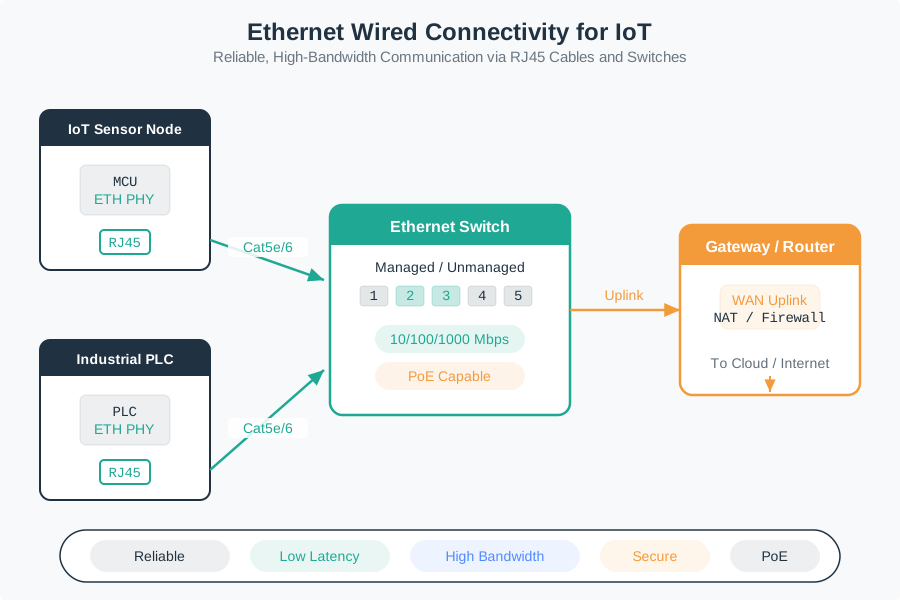
Ethernet is often chosen for IoT when the deployment needs predictable delivery more than mobility. A switched full-duplex link gives each device a dedicated path to a switch port, so the design removes radio contention and the old shared-medium collision model.
That reliability is not automatic. It depends on cable length, terminations, switch capacity, power budget, VLAN design, grounding, UPS coverage, and testing. A good Ethernet design records those constraints before the device is mounted high on a wall or bolted into a cabinet.
The practical contract is broader than “plug in a cable.” The device needs a cable plant that can hold the negotiated speed, a switch port with enough power and buffering, a labeled path through patch panels, and an upstream route that will not be saturated by video, telemetry, firmware updates, or management traffic. A stationary sensor may have a stable copper link while the service still fails because the closet switch lost UPS power or because several cameras share an undersized uplink.
For IoT teams, Ethernet is usually the right answer when physical access is possible and the device must be observable for years. The cable gives technicians a place to test continuity, pair order, length, link speed, duplex mode, PoE class, and error counters. Those measurements turn connectivity into evidence that can be reviewed before blaming firmware, cloud services, or radio coverage.
This is why the access-link decision should be made with facilities, network operations, and device owners in the same review. The cable route, switch closet, breaker panel, and maintenance window all become part of the connectivity design.
Figure 35.2: Ethernet IoT topology showing sensor and PLC devices connected through Cat5e or Cat6 cables to an Ethernet switch, gateway uplink, and PoE-capable network path.
Reliability area
What Ethernet improves
What still must be checked
Dedicated link
Each device gets its own switched port, so a camera or controller does not compete for airtime with neighboring devices.
Cable category, termination quality, link speed, duplex mode, and port error counters.
Shared switch
The switch fabric, uplink, VLAN policy, and buffering replace radio airtime as the shared resource.
Uplink capacity, switch buffering, VLAN policy, loop prevention, and monitoring.
Power path
PoE turns the network cable into the power path.
Wattage, port class, cable loss, inrush current, and backup power.
Decision signal
Choose Ethernet when the device is stationary and the value of stable bandwidth, power, security, or deterministic timing justifies the cable run.
35.9 Ethernet Deployment Record
A practical Ethernet record shows that the physical link, power budget, and network service all match the device’s job. This matters because most field failures are not caused by the Ethernet standard itself; they are caused by underspecified installation details.
Start the record at the device and walk outward. Capture the device model, MAC address, expected data rate, required PoE standard, cable category, measured run length, patch-panel label, switch, port number, VLAN, IP addressing source, gateway path, and owner. Then attach evidence: cable certification or tester results, observed negotiated speed and duplex, switch PoE allocation, baseline error counters, and a short load calculation for the uplink. This makes the installation auditable when a technician replaces a switch, moves a patch lead, or adds another high-bandwidth device to the same closet.
The record should also state the design margin. A PoE installation that passes at idle can still fail when heaters, pan-tilt motors, infrared illuminators, or radios enter peak draw. A gigabit access port can still become a bottleneck if many devices converge through a single 1 Gb/s uplink. Treat these margins as acceptance criteria during commissioning, not as notes to investigate after the deployment is already in service.
Record field
Example value
Why it matters
Evidence to keep
Link speed and media
1000BASE-T over Cat6, 72 m run
Speed only holds if the cable category, length, and terminations support it
Cable-test report and negotiated link speed
PoE class
PoE+ camera, 25 W max, 30 W port
Total switch budget and per-port class both have to fit
Device datasheet and switch PoE allocation screen
Traffic load
25 Mbps stream plus control and management traffic
Uplinks, storage, and monitoring paths can bottleneck even when access ports are gigabit
Bandwidth calculation and switch utilization capture
Reliability controls
UPS-backed switch, tested cable, VLAN, alert on port errors
Ethernet removes RF risk but still needs power, physical, and operations proof
UPS runtime, VLAN map, error-counter baseline
Deployment moment
Checks to perform
Commissioning
Verify continuity, pair order, cable length, link speed, duplex, PoE class, and device boot under worst-case power draw.
Operations
Monitor link flaps, CRC errors, PoE power draw, switch temperature, uplink utilization, and unexpected speed downgrades.
Change control
Record which switch port, VLAN, cable route, and patch-panel label belong to each device so maintenance does not create hidden outages.
The deployment record is where the earlier choices become accountable. If the field evidence does not match the planned speed, power, and route, the release should pause before the device becomes hard to reach.
Escalation trigger
If a cable run approaches 100 m, a PoE budget exceeds 80%, or a port negotiates below the planned speed, treat the installation as a design issue, not a firmware issue.
35.10 Duplex Fixes Collisions Only
Modern switched Ethernet does not use CSMA/CD on full-duplex links, so classic Ethernet collisions are gone. The failure modes move elsewhere: damaged pairs, marginal connectors, cable attenuation, duplex or speed mismatch, oversubscribed uplinks, PoE overload, spanning-tree loops, and unmanaged broadcast traffic.
Industrial Ethernet and TSN add another layer: timing becomes a scheduled resource. The physical link can be healthy while the system still fails if time-aware shapers, VLAN priority, clock synchronization, or switch queueing are misconfigured.
At link-up, auto-negotiation exchanges advertised capabilities and chooses speed, duplex, and flow-control behavior. A bad pair, poor termination, or marginal connector may still produce a link, but the port can downshift, flap, or accumulate frame check sequence and CRC errors under load. These symptoms are physical-layer evidence. They should be checked against cable length, bend radius, connector quality, electromagnetic exposure, and the actual speed reported by both ends of the link.
Above the cable, switching behavior decides whether the reliable access link remains useful. MAC address learning directs frames to the right port, VLAN tags separate traffic domains, and spanning tree or rapid spanning tree prevents loops when redundant paths exist. If those controls are wrong, broadcast storms, blocked ports, or accidental VLAN leaks can break devices whose local link lights still look healthy. PoE adds another hidden state machine: the powered device and power sourcing equipment classify load, apply power, and must survive inrush and peak draw without exhausting the switch budget.
An 802.1Q VLAN tag is a four-byte field inserted into the Ethernet frame after the source MAC address. The tag uses EtherType 0x8100, carries priority bits for traffic handling, and uses a 12-bit VLAN identifier, which gives 4096 possible codes before reserved values and operational policy reduce the usable set. Access ports usually send ordinary untagged frames for one assigned VLAN; trunk ports carry tagged frames for multiple VLANs. A configured native VLAN is the compatibility exception on many trunks: frames for that VLAN cross the trunk without a tag, so the native VLAN must be documented and kept consistent to avoid accidental leakage or confusing packet captures.
Long cable routes add a security and maintenance problem that a short patch lead hides. A submarine fiber, campus backbone, buried sensor trunk, or utility-corridor Ethernet run can fail because the cable is cut, crushed, flooded, bent past its radius limit, tapped, or damaged by construction and wildlife. Treat those runs as field infrastructure: record the route, burial or conduit protection, splice points, inspection owner, and the expected signal margin before the service depends on it.
Physical tapping is part of that review. A conductive tap makes direct electrical contact with a copper conductor; an inductive tap couples to electromagnetic fields and may be harder to notice because it does not require the same visible break. Optical fiber changes the details but not the principle: a bend, splice, or clamp can leak or disturb signal energy. Countermeasures start with physical inspection and route control, then add protective conduit, pressurized or monitored enclosures where justified, faster bitrate or optical-power baselines that make loss changes visible, and alarms on unexpected error, attenuation, or spectrum changes.
Time-domain reflectometry (TDR) turns cable troubleshooting into a measurement instead of a guess. The tester sends a pulse down the line and measures reflected energy. The delay estimates distance to the anomaly; the shape helps distinguish an open cut, short, bad termination, moisture intrusion, crushed section, splice, or tap. The same idea explains why a wave pulse reflects differently at a soft boundary than at a hard boundary: impedance changes decide what returns to the tester.
Pete’s Delivery Slip
Address: a deployment record starts at the device – model, MAC, cable category, and measured run length.
Route: switch, port, VLAN, and gateway path all belong in the same record as the cable itself.
Receipt: a TDR pulse’s delay names the distance to a fault, and its shape says whether it’s a cut, short, or bad termination.
Environmental protection belongs in the same record. Rodents may chew cable jackets, insects may attack fills or seals, birds may nest on aerial routes, and water can enter damaged sheath or poor glands. A robust design uses the right sheath, armored or wrapped sections where needed, sealed joints, strain relief, slack loops, drip paths, and periodic inspection. The important lesson for IoT is operational: do not call a wired link “reliable” until the physical route has a diagnostic method and a maintenance plan.
For deterministic industrial traffic, the failure pattern can be even subtler. Time-Sensitive Networking features such as IEEE 802.1AS time synchronization and IEEE 802.1Qbv time-aware scheduling depend on compatible devices, clock design, queue configuration, and profile discipline across the path. A single unmanaged switch, gateway boundary, or unverified queue policy can destroy timing even though ordinary pings and file transfers appear normal.
Failure area
Typical evidence
First checks
Physical errors
CRC errors, link flaps, and speed downgrades
Cable, connector, length, bend radius, and electromagnetic environment
Power errors
Reboots, brownouts, or PoE class warnings under load
Class negotiation, inrush draw, total budget, cable loss, and UPS behavior
Switching errors
Devices unreachable despite good link lights
Loops, VLAN mistakes, congested uplinks, blocked ports, and broadcast storms
Checkpoint: Operations Evidence
You now know:
A reliable Ethernet record includes device identity, cable category, run length, switch port, VLAN, PoE class, and owner.
CRC errors, link flaps, speed downgrades, and PoE class warnings are physical evidence, not vague connectivity symptoms.
A run near 100 m, PoE utilization above 80%, or a port below planned speed should trigger design review.
Knowledge Check: PoE Deployment Record
35.11 Summary
Ethernet remains the gold standard for wired IoT connectivity, offering unmatched reliability and performance for stationary devices.
Key Takeaways
When to Use Ethernet:
High-bandwidth applications (video, large data transfers)
Mission-critical systems requiring deterministic timing
Security-sensitive deployments (no wireless eavesdropping)
Static installations where cabling is feasible
Devices that can benefit from PoE (cameras, access points, sensors)
Ethernet Standards for IoT:
10BASE-T: 10 Mbps for legacy equipment and simple low-data-rate sensors.
100BASE-T: 100 Mbps for microcontrollers and basic IoT gateways.
1000BASE-T: 1 Gbps for cameras, gateways, and industrial systems.
PoE (802.3af): 15.4 W for basic cameras, VoIP phones, and sensors.
PoE+ (802.3at): 30 W for 4K cameras, Wi-Fi 6 access points, and access-control devices.
PoE++ (802.3bt): 60 W or 100 W for PTZ cameras, displays, thin clients, and other high-power devices.
Best Practices:
Use PoE whenever possible to simplify installation
Plan cable runs during construction (cheaper than retrofit)
Use Cat6 or better for future-proofing
Consider TSN for industrial control applications
Ethernet for backbone, wireless for edge where needed