19 Anatomy of a Connected Device
connected device fundamentals, IoT device review, device boundary, IoT endpoint roles, connected device lifecycle, device tradeoff evidence
19.1 Start Simple
Every connected device is both a physical object and a service endpoint. Start by naming what it senses or controls, how it gets power and connectivity, what local feedback it gives, what data leaves it, and which maintenance or security decision would change the experience.
19.2 In 60 Seconds
A connected device is the physical part of an IoT system that senses, acts, displays, stores, relays, or controls information at the edge of the physical world. It is not only a circuit board. It has a physical boundary, power source, connectivity path, firmware behavior, maintenance model, and user or installer context.
Fundamental review asks whether those pieces fit the device role. A small battery endpoint, an actuator, a gateway, and a public infrastructure node need different evidence, even when they use similar sensors or radios.

Phoebe’s Why
This chapter’s “fifteen-minute freshness to meet a two-year battery target” is a charge-budget claim, but a coin cell’s real failure mode is usually not running out of charge – it is voltage sag. A coin cell’s internal resistance is small when fresh but climbs sharply as the cell empties, and Ohm’s law says that resistance steals more of the open-circuit voltage every time the radio pulls a transmit burst. A cell can still hold most of its rated milliamp-hours and still sag below the radio’s brownout threshold the instant it has to push real current – which is also why this chapter is right to say a bench-validated radio can fail once it is mounted near metal: a detuned antenna needs more current (or more retries) for the same range, and that extra burst current is exactly what a resistance-limited coin cell struggles to deliver.
The Derivation
Energy from charge and voltage, discounted by a design margin \(f_{derate}\) covering self-discharge and temperature:
\[E = Q_{usable}\times V, \qquad Q_{usable} = f_{derate}\times Q_{nominal}\]
Ohm’s-law voltage sag under a transmit-burst current \(I\) through internal resistance \(R_{int}\):
\[V_{term} = V_{oc} - I\,R_{int}\]
Average current from sleep and active duty cycle \(d = T_{active}/T_{interval}\), giving the service-life budget:
\[I_{avg} = I_{sleep}(1-d) + I_{active}\,d, \qquad t_{life} = \frac{Q_{usable}}{I_{avg}}\]
Antenna gain sets EIRP for a fixed transmit power, so a detuned (lower or negative dBi) antenna needs more conducted power, hence more \(I_{active}\), to close the same link:
\[\mathrm{EIRP(dBm)} = P_t(\mathrm{dBm}) + G(\mathrm{dBi})\]
Worked Numbers: The Coin-Cell Beacon’s Real Limit
The chapter names no cell or radio, so the worked numbers use a catalog-typical CR2032 (\(Q_{nominal}=220\) mAh, \(V=3.0\) V) and nRF52-class BLE beacon:
- Usable energy (\(f_{derate}=0.8\)): \(Q_{usable}=176\) mAh, \(E_{usable}=0.8\times0.660=0.528\) Wh
- 2-year current budget: \(17{,}520\) h \(\times I_{avg} = 176\) mAh gives \(I_{avg,budget}=10.0\ \mu\text{A}\)
- 15-minute report duty cycle (\(I_{active}=8\) mA for a 3 ms advertising burst, \(I_{sleep}=1\ \mu\text{A}\)): \(d=3.33\times10^{-6}\), \(I_{avg}=1.03\ \mu\text{A}\), \(t_{life}=171{,}000\) h \(\approx19.6\) years – a \(9.8\times\) margin over the two-year target on charge alone
- Voltage sag on that same 8 mA burst: fresh cell (\(R_{int}=10\ \Omega\)) sags \(0.08\) V, easily survivable; a near-empty cell (catalog-typical \(R_{int}=200\ \Omega\) late in discharge) sags \(8\text{mA}\times200\Omega=1.60\) V, pulling the terminal voltage to about \(1.4\) V during the burst – likely below a BLE SoC’s brownout floor
So the two-year claim rarely fails on the mAh column; it fails when a rising-resistance cell can no longer survive the burst current the radio needs, and that burst current is exactly what an installed-context antenna problem makes worse.
19.3 Learning Objectives
By the end of this chapter, you will be able to:
- define a connected device by role, boundary, inputs, outputs, power, connectivity, and maintenance context
- distinguish endpoint, actuator, gateway, interface, and infrastructure roles in an IoT system
- explain how power, connectivity, sensing, actuation, compute, enclosure, and service constraints interact
- identify evidence needed before accepting a connected-device design claim
- write a bounded connected-device record with assumptions, owners, limits, and change conditions
19.4 Minimum Viable Understanding
Connected-device fundamentals are about fit. A device is reviewable when another person can see what it does, where it lives, how it is powered, how it communicates, how it is updated, how it is maintained, and what changes would require a new review.
Avoid starting from a category label such as “wearable,” “industrial,” or “smart home.” Start from the device’s role and evidence. Category labels can help organize examples, but they do not prove that a design works.
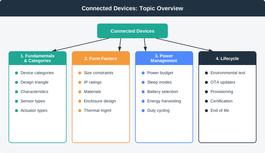
Use Figure 19.1 to keep this chapter in scope. Fundamentals name the role, boundary, evidence, and tradeoff; later chapters inspect form factor, power, and lifecycle evidence in more detail.
19.5 Prerequisites
This chapter builds on:
- Device Form Factors, which reviews physical design evidence.
- Connected Devices Lifecycle, which connects device design to operation and maintenance.
- Power Management, which reviews battery and power-state tradeoffs.
- IoT Reference Models, which places devices inside the system architecture.
19.6 Connected Device Boundaries
A connected device is the place where software promises meet the physical world. The device may be a battery sensor, a lock actuator, a gateway, a wall display, or a public infrastructure node, but the review always starts by naming what the device owns locally and what it depends on elsewhere.
For a smart lock, the device boundary includes the motor, door position sensor, keypad or reader, BLE or Thread radio, battery pack, enclosure, firmware, credential storage, reset path, and update behavior. The phone app, Matter controller, Wi-Fi bridge, cloud service, and support tool may all be part of the product experience, but they are not the same device boundary.
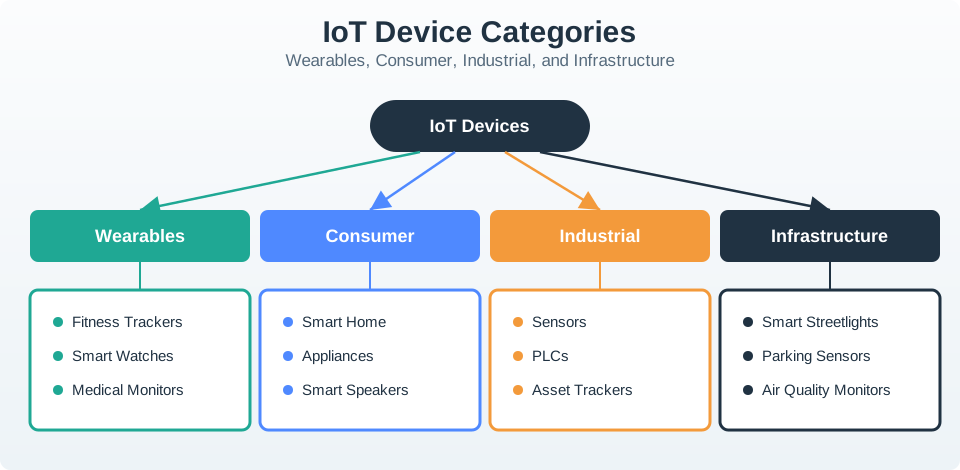
The same category can hide very different review needs. A wearable fitness tracker, a hospital patient tag, and a worker safety badge are all wearable devices, but they differ in accuracy expectation, cleaning exposure, attachment method, privacy boundary, alert escalation, battery charging habit, and support workflow. A consumer smart plug, an industrial relay node, and a streetlight controller may all switch power, but their installation authority, local safe state, audit trail, firmware-update risk, and outage consequence are not comparable.
That is why the first review question is not “what type of product is this?” but “what responsibility does this physical device carry?” A sensor endpoint owns sampling, timestamping, freshness, and power state. An actuator endpoint owns command authorization, confirmation, interlock, manual override, and safe failure. A gateway owns local-device admission, buffering, protocol translation, time source, identity, and partial-failure reporting. A display or interface owns status clarity, accessibility, local controls, and recovery guidance.
- Role: Decide whether the device senses, actuates, relays, displays, controls, or combines several roles.
- Context: Name the installation environment, user access, service interval, and failure consequence.
- Dependency: Name the gateway, phone, cloud, local controller, or operator action required for the device to keep its promise.
19.7 Device Hard-Constraint Review
Useful connected-device review starts with constraints that cannot be solved in the app later. A coin-cell nRF52 beacon, an ESP32 Wi-Fi prototype, an STM32 LoRaWAN sensor, and a mains-powered gateway may all send telemetry, but their radio airtime, sleep current, antenna placement, flash layout, thermal envelope, and maintenance path are different.
Connectivity also has to be checked in the installed context. BLE, Thread, Zigbee, Matter, Wi-Fi, LoRaWAN, LTE-M, NB-IoT, Ethernet, RS-485, Modbus, and IO-Link each move the boundary between the device, gateway, installer, and service owner. A bench test with the cover open does not prove performance inside a metal cabinet, freezer, basement, moving vehicle, or outdoor enclosure.
Build the review record from measurable constraints. For power, record sleep current, wake source, transmit duration, actuator current, brownout threshold, low-battery behavior, replacement path, and service interval. For connectivity, record join method, pairing ownership, retry limit, queue behavior, stale-data rule, local fallback, gateway dependency, and what the receiving system can distinguish. For compute and storage, record which rules run locally, what survives restart, which data is buffered, and how firmware updates are staged and rolled back.
Then test the constraint in a realistic sequence. A doorway sensor should be mounted in the doorway, with the enclosure closed, the gateway in its expected location, the battery state measured, the receiver showing fresh versus stale readings, and the reset or replacement path attempted by the person who will maintain it. A gateway should be tested with endpoint churn, local-protocol errors, clock drift, offline buffering, backhaul recovery, and partial failure displayed to support staff rather than hidden behind a single online status.
- Map the physical path. Include enclosure, mounting, sensor opening, antenna clearance, cable strain, IP rating, and service access.
- Map the power path. Include sleep states, transmit bursts, actuator current, brownout behavior, battery replacement, and charging or harvesting limits.
- Map the recovery path. Include pairing reset, local fallback, watchdog restart, OTA rollback, credential rotation, and decommissioning.
The accepted device decision should state the tradeoff. A coin-cell sensor may accept fifteen-minute freshness to meet a two-year battery target. A mains-powered gateway may accept higher local compute because it can buffer and diagnose endpoint failures. A lock actuator may reject cloud-only command handling because local override and safe failure matter more than implementation simplicity. The record should make those choices visible enough that a later radio, enclosure, battery, firmware, or deployment change triggers the right follow-up review. ## Trust in State and Services {.depth-l2}
A connected device becomes trustworthy when its local state is explicit. Firmware should separate sensed value, command intent, actuator result, radio status, time source, configuration version, update slot, and fault reason instead of collapsing everything into “online” or “working.”
Storage choices matter because device history may survive loss of power, ownership transfer, or a failed update. Internal flash, FRAM, EEPROM, a secure element such as ATECC608A, or a TPM-class module may hold keys, counters, calibration, boot flags, rollback images, or pairing secrets. Each item needs a lifetime, reset rule, and protection level that matches the device role.
State transitions deserve the same attention as hardware. A device may move through manufactured, provisioned, commissioned, normal, degraded, offline, updating, rollback, factory-reset, ownership-transfer, and retired states. Each state should define what commands are accepted, which credentials are active, which data is retained, whether actuation is allowed, how the user sees the condition, and what support can inspect. If those states are implicit, field failures become ambiguous and recovery procedures become unsafe.
Gateway and mixed-role devices add another layer of state. They may track endpoint membership, local network health, backhaul reachability, clock confidence, translation errors, buffer pressure, duplicate suppression, schema versions, tenant or site binding, and update compatibility. A gateway that keeps accepting endpoint commands while its cloud path is down may create stale automation. A gateway that drops buffered data silently may turn a local radio fault into a misleading cloud dashboard. Review evidence should expose those boundaries.
- Identity: Define provisioning, certificate or key storage, ownership transfer, and revocation before field installation.
- Observability: Preserve enough counters, timestamps, firmware versions, and fault codes for support to distinguish device, gateway, and service failures.
- Safety: Keep actuator interlocks, manual override, local safe state, and offline behavior independent from cloud availability when physical harm or lockout is possible.
The low-level implementation evidence should connect back to the user-facing promise. If a device promises reliable occupancy status, its firmware must show sample timestamps, debounce rules, confidence or stale flags, retry behavior, and receiver semantics. If a device promises remote control, it must show authorization, command expiry, idempotency, result confirmation, and local safe state. If a device promises easy service, it must show reset paths, diagnostic codes, update rollback, replacement identity, and decommissioning behavior.
19.8 Connected Device Review Map
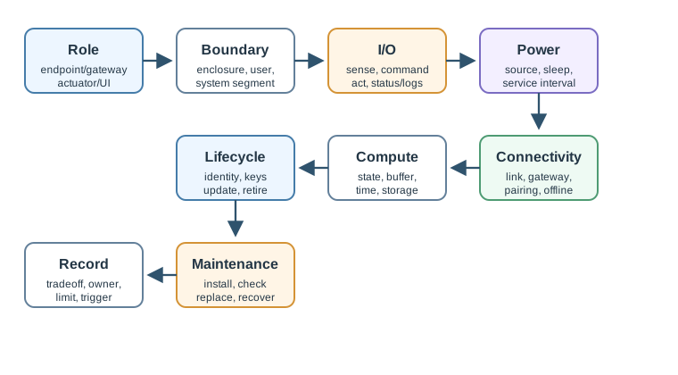
Use Figure 19.3 to keep review work grounded:
- Role: endpoint, actuator, gateway, controller, display, interface, or infrastructure node.
- Boundary: enclosure, mounting, user access, environment, and system segment.
- Inputs and outputs: sensors, events, commands, actuation, display, status, and logs.
- Power: battery, mains, harvesting, sleep states, service interval, and replacement path.
- Connectivity: local radio, wired link, wide-area link, gateway path, pairing, and fallback.
- Compute and storage: local decision, buffering, timestamps, logs, credentials, and update space.
- Security and updates: identity, provisioning, update path, rollback, reset, and decommissioning.
- Maintenance: install, inspect, clean, replace, calibrate, recover, and retire.
- Decision and change control: accepted tradeoff, owner, limit, and condition to reopen the record.
19.9 Device Boundary
The device boundary is where physical and digital responsibilities meet.
Review:
- what hardware is inside the enclosure
- what external sensors, cables, antennas, batteries, or mounting parts are part of the device
- which gateway, phone, cloud service, or local controller the device depends on
- what the user, installer, technician, or operator must touch
- what data and control authority the device owns locally
- what state survives restart, replacement, reset, or network loss
If the boundary is unclear, later claims about power, connectivity, updates, or maintenance will also be unclear.
19.10 Device Roles
A connected device may have one primary role or several roles combined.
Sensor endpoint
Measures the environment or a system state. Review sensor placement, sampling, calibration, timestamps, local filtering, power state, and stale-data behavior.
Actuator endpoint
Changes the physical world. Review command identity, safe state, confirmation, manual override, local interlock, and recovery after restart or network loss.
Gateway
Connects local devices to another network or service. Review protocol translation, buffering, identity, time source, offline behavior, update path, and failure isolation.
Interface device
Provides status, controls, display, notification, or setup interaction. Review labels, feedback, accessibility, pairing, reset, and what can be done without a phone or cloud service.
Infrastructure node
Operates at scale or in places that are hard to service. Review installation repeatability, maintenance interval, weather or site exposure, asset identity, update policy, and replacement process.
The role should match the evidence. A gateway cannot be reviewed like a simple sensor endpoint, and an actuator cannot be reviewed like passive telemetry.
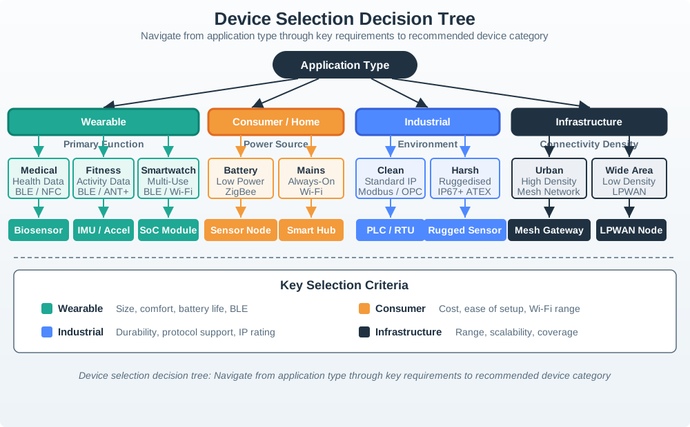
Use Figure 19.4 as a starting prompt, not as a substitute for review. It helps teams ask which category and constraint family they are dealing with, then the record still has to prove role, boundary, power, connectivity, update, maintenance, and failure behavior.
19.11 Core Building Blocks
Connected devices combine several building blocks:
- Sensing or input: physical signal, user action, local event, or external device state.
- Actuation or output: motor, relay, display, sound, light, notification, or control message.
- Compute: firmware logic, state machine, filtering, inference, safety check, or local policy.
- Storage: configuration, identity, logs, buffered data, update package, or calibration data.
- Connectivity: wired, local wireless, wide-area, gateway-assisted, or intermittent link.
- Power: mains, battery, charging, harvesting, or mixed source.
- Physical shell: enclosure, mounting, sensor opening, antenna path, seal, label, and service access.
- Lifecycle controls: provisioning, update, reset, monitoring, repair, replacement, and decommissioning.
The review should not treat these blocks as independent. Changing one often changes another.
19.12 Tradeoffs That Matter
Connected-device design is usually a set of bounded tradeoffs rather than one perfect answer.
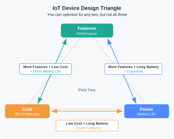
Use Figure 19.5 when a device claim sounds unconstrained. A feature-rich, cheap, long-battery product may be a goal, but the review needs evidence for which two constraints are being prioritized and what limit is accepted.
Power versus capability
More frequent sensing, stronger radio use, brighter displays, local compute, and always-on status can increase usefulness, but they also change heat, battery size, charge interval, and service burden.
Connectivity versus installation
A radio that works well on a bench can fail after the device is mounted near metal, the body, water, machinery, walls, or underground material. Connectivity evidence belongs in the installed context.
Local behavior versus system dependence
Local decision-making can improve responsiveness and resilience, but it needs storage, update, reset, and policy evidence. Cloud-dependent behavior can simplify the device, but it needs offline and recovery evidence.
Simplicity versus maintainability
A sealed device can be durable, but service, reset, battery replacement, calibration, and disposal may become harder. A serviceable device can be easier to maintain, but openings and connectors add protection and assembly risks.
19.13 Evidence For Device Claims
A connected-device record should support claims with evidence such as:
- device role and system boundary notes
- installation or placement assumptions
- power-state and service-interval evidence
- sensor or actuator behavior observations
- connectivity checks in the intended mounting context
- local state, buffering, and restart behavior
- provisioning, update, rollback, reset, and decommissioning path
- maintenance, replacement, cleaning, or calibration steps
- known limits and change conditions
The goal is not to document every implementation detail. The goal is to make the design decision reviewable.
19.14 Worked Review: Battery Sensor Endpoint
A small endpoint samples a physical condition and reports values through a gateway.
Review evidence
- Sensor placement and sampling purpose are clear.
- The receiver can distinguish fresh, stale, duplicate, and missing values.
- The sleep, wake, transmit, and retry behavior fits the service interval.
- The gateway dependency is recorded.
- The battery replacement or recharge path is practical for the deployment.
- Firmware update and reset behavior are documented.
Likely review action
Hold the decision if the record only says “low-power sensor” without showing the sampling purpose, power states, receiver freshness rule, gateway dependency, and maintenance path.
Change condition
Rerun the review when the sampling interval, radio, gateway, battery, enclosure, receiver rule, update policy, or installation location changes.
19.15 Worked Review: Gateway Device
A gateway aggregates nearby device traffic and forwards selected data to another system.
Review evidence
- The gateway role is separated from the endpoint roles.
- Protocol translation and buffering rules are visible.
- Local time, identity, and configuration ownership are clear.
- Offline behavior is documented.
- The gateway update path does not strand endpoints.
- Logs or status can show partial failure instead of hiding it.
Likely review action
Ask for a gateway record if the design treats the gateway as a transparent cable. Gateways often change reliability, timing, identity, and security boundaries.
Change condition
Rerun when endpoint count, local protocol, wide-area path, buffering policy, identity model, time source, update path, or installation context changes.
19.16 Connected Device Record
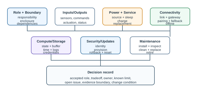
Figure 19.6 shows the fields to preserve:
- Role and boundary: what the device is responsible for and where that responsibility ends.
- Inputs and outputs: sensed data, user input, commands, status, actuation, and logs.
- Power and service: power source, sleep behavior, charge or replacement path, and service interval.
- Connectivity: local link, gateway path, pairing, fallback, offline behavior, and installed-context evidence.
- Compute and storage: local rules, state, buffering, timestamps, credentials, and update space.
- Security and updates: identity, provisioning, update, rollback, reset, and decommissioning.
- Maintenance: install, inspect, clean, calibrate, replace, recover, and retire.
- Decision and change control: accepted tradeoff, owner, known limit, open issue, and trigger.
19.17 Common Findings
- The design uses a category label instead of a role and boundary record.
- The device role mixes endpoint, actuator, gateway, and interface responsibilities without evidence.
- Power claims do not include service or replacement assumptions.
- Connectivity was tested only before installation.
- Sensor or actuator behavior is described without receiver or safe-state evidence.
- Update, reset, rollback, or decommissioning paths are missing.
- Maintenance depends on tools, access, or permissions that are not recorded.
- The record lacks a change condition after radio, battery, enclosure, firmware, gateway, or deployment changes.
19.18 Review Checklist
Before accepting a connected-device fundamentals decision, confirm that the record includes:
- device role and physical/system boundary
- inputs, outputs, sensing, actuation, status, and logs
- power source, power states, service interval, and maintenance path
- connectivity path, gateway dependence, pairing, fallback, and installed-context evidence
- compute, storage, buffering, restart, and local-state behavior
- identity, provisioning, update, rollback, reset, and decommissioning path
- installation, maintenance, calibration, replacement, and recovery steps
- accepted tradeoff, owner, known limit, open issue, and change condition
19.19 Knowledge Check
19.20 Matching Quiz
19.21 Ordering Quiz
19.22 Summary
Connected devices are physical system participants with roles, boundaries, inputs, outputs, power needs, connectivity paths, compute and storage behavior, security and update controls, maintenance expectations, and lifecycle limits.
The strongest review habit is to make each device claim bounded and inspectable. A device is ready for acceptance when its role, boundary, power, connectivity, local behavior, maintenance, and change conditions are visible enough for another reviewer to repeat the decision.
19.23 Key Takeaway
Connected devices succeed when physical constraints, power, sensing, communication, feedback, and maintenance are designed as one user-facing system.
19.24 Concept Relationships
- Device Form Factors reviews the physical shell, mounting, and interaction surfaces that support the device role.
- Power Management expands the power-state and battery evidence introduced here.
- Connected Devices Lifecycle follows the device through provisioning, operation, maintenance, and retirement.
- IoT Reference Models places connected devices inside the larger system architecture.
19.25 What’s Next
Continue to Connected Devices Lifecycle to review how connected-device decisions change across provisioning, operation, maintenance, and retirement.