39 Light and Proximity Readout Physics
39.1 Start With the Measurement Story
Light and proximity readouts depend on physics before code. Begin with reflection, distance, angle, ambient light, and detector response, then decide which reading pattern proves an object is truly present.

Phoebe’s Why
A photodiode’s current is not an arbitrary calibration constant; it counts photons. Each absorbed photon carries a fixed energy set by its wavelength, and with some probability it frees one electron-hole pair – one photon in, at most one electron out. Every freed pair is one electron of current, so the ratio of current to optical power is fixed by the photon’s own energy, not by circuit design. That is why an infrared photodiode produces more current for the same optical power than a shorter-wavelength diode of equal quantum efficiency: each photon still only frees one electron, but a watt of infrared light is carried by more, lower-energy photons than a watt of visible light.
The Derivation
Photon energy sets how many photons a given optical power delivers per second:
\[E_{photon} = \frac{hc}{\lambda}\]
Quantum efficiency \(\eta\) is the fraction of absorbed photons that free a usable electron, so the photocurrent is:
\[I_{photo} = \eta\, q\, \frac{P_{optical}}{E_{photon}} = \frac{\eta\, q\, \lambda}{hc}\,P_{optical}\]
which defines responsivity, the constant this chapter’s transimpedance formula treats as given:
\[R = \frac{I_{photo}}{P_{optical}} = \frac{\eta\, q\, \lambda}{hc} \]
Worked Numbers: Inverting This Chapter’s Own 1 \(\mu\)A Example
- Photon energy at 850 nm (typical proximity-sensor IR): \(E_{photon} = (6.626\times10^{-34})(3.00\times10^8)/(850\times10^{-9}) = 2.34\times10^{-19}\) J \(= 1.46\) eV
- Ideal responsivity (100% quantum efficiency): \(R_{max}= q/E_{photon} = 0.685\) A/W
- Catalog-typical silicon photodiode at 850 nm, \(\eta\approx0.8\): \(R = 0.8\times0.685 = 0.548\) A/W – in the same range silicon IR photodiode datasheets typically quote
- Inverting the chapter’s own \(I_{photo}=1\ \mu\text{A}\): \(P_{optical} = I_{photo}/R = 1\times10^{-6}/0.548 = 1.82\ \mu\text{W}\) – a faint but physically reasonable reflected-IR power for a nearby object, confirming the chapter’s transimpedance example describes a real, not an arbitrary, optical signal
39.2 Learning Objectives
After this page, you should be able to:
- Separate light intensity, proximity, presence, touch, and distance as different measurement questions.
- Explain how photodiodes, LDR voltage dividers, PIR modules, ultrasonic sensors, and capacitive sensors produce readings.
- Compute ultrasonic distance from echo time and distinguish it from optical time-of-flight hardware.
- Diagnose reflectance ambiguity, ambient-light interference, temperature drift, and photodiode noise limits.
- Record thresholds with units, geometry, readout chain, and calibration evidence.
39.3 After Light and Proximity Labs
Light and Proximity Sensor Labs walks through practical devices and wiring. Those labs only become reliable when the reading is interpreted through the right physics. A BH1750 lux value, an LDR ADC count, a PIR digital pulse, an HC-SR04 echo time, and a capacitive touch count do not answer the same question.
Use this page when a threshold behaves differently after mounting, target material, sunlight, temperature, or divider orientation changes. The goal is to decide whether the sensor measures light level, reflected intensity, motion, field disturbance, or true distance before turning a number into an automation rule.
39.4 Overview: Photons In, Current Out
Every light and optical-proximity sensor rests on one idea: light carries energy, and certain semiconductors turn that energy into a measurable electrical signal. A photodiode is the workhorse — incoming photons free charge carriers, producing a current proportional to how much light lands on it. That is optical transduction.
Proximity is a related but distinct problem, and there are several very different ways to solve it. You can shine infrared light and measure how much bounces back — simple, but it only reliably tells you something is there. You can measure how long light or sound takes to return — time-of-flight — which gives a true distance. You can also sense field disturbance with a capacitive plate, which is useful for touch and near-field presence but not for long-range distance.
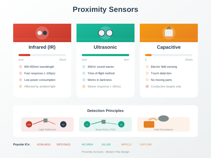
Intuition: reflected-intensity sensing is like judging distance by how bright a flashlight looks — fooled by dark or shiny surfaces. Time-of-flight is like clapping and timing the echo — it measures distance directly, regardless of how reflective the target is.
Light-sensing labs often mix all three ideas, so read the sensor value before designing the threshold. An LDR divider gives an ADC count whose meaning depends on the fixed resistor and room lighting. A BH1750 gives calibrated lux over I2C, so thresholds can be written in physical units such as "turn on below 40 lux". A PIR module does not report lux or distance at all; it reports a changing infrared pattern caused by warm motion. An HC-SR04 ultrasonic module reports echo time, so its number becomes distance only after the round-trip calculation.
Infrared sensing also needs a wavelength note. Near-infrared channels usually behave like optical systems: emit or observe light and interpret reflection, interruption, or time-of-flight. Far-infrared and thermal imagers observe heat radiation from bodies and surfaces, so they support presence, hot-spot, or temperature-pattern claims rather than ordinary colour or brightness claims. A PIR occupancy sensor sits in that thermal-infrared family but reports change across its zones, not a still person's identity or an absolute temperature map.
That distinction changes the lab question. For ambient light, ask "how bright is the scene?". For IR reflection, ask "did enough light return to prove a nearby target?". For ultrasonic or optical time-of-flight, ask "how long did the emitted pulse take to return?". Once students attach each sensor to the physical quantity it really measures, false conclusions are easier to catch: a black object may look farther to an IR reflector, a sunlit window may saturate a photodiode, and a cold room shifts an ultrasonic distance.
Overview Knowledge Check
39.5 Transimpedance and ToF Readout
A photodiode's current is often tiny, so a transimpedance amplifier converts it to a usable voltage. An LDR is different: it is a variable resistor, so the normal lab circuit is a voltage divider into an ADC. For ranging, distance comes from an echo time. Keeping those three readout patterns separate prevents the common mistake of treating every light-related sensor as if it returned lux.
Transimpedance amp:  Vout = Iphoto × Rf
LDR divider:         Vadc = Vcc × Rfixed / (Rldr + Rfixed)   (one common orientation)
Time-of-flight:      distance = (speed × time) / 2   (round trip)
  light:      speed = 3.0e8 m/s
  ultrasound: speed ≈ 343 m/s at 20 °C
Worked examples: an analog light front-end, lux threshold, and ultrasonic ping
Photodiode -> transimpedance amplifier:
  Iphoto = 1 µA, feedback Rf = 1 MΩ
  Vout = 1e-6 × 1e6 = 1.0 V   (readable by an ADC)

LDR divider, Vcc = 3.3 V, Rfixed = 10 kΩ to ground:
  bright desk: Rldr = 3 kΩ   -> Vadc = 3.3 × 10 / (3 + 10) = 2.54 V
  dim corner:  Rldr = 60 kΩ  -> Vadc = 3.3 × 10 / (60 + 10) = 0.47 V

BH1750 lux threshold:
  reading = 28 lux, rule = turn task light on below 40 lux
  action = ON, because the reading is a calibrated physical unit

Ultrasonic ranging (HC-SR04 style):
  Measured echo time = 5.83 ms
  distance = 343 × 0.00583 / 2 = 1.00 m

Light time-of-flight is far faster:
  1 m round trip = 2 / 3e8 = 6.67 ns
  (needs dedicated timing hardware, e.g. a VL53L0X)
The 6.67 ns figure is why optical time-of-flight modules integrate their own precision timing circuitry — no ordinary microcontroller can time nanoseconds, but it can happily time a 5.83 ms ultrasonic echo.
In a lab notebook, record the readout chain with the threshold, not just the final threshold. A threshold of 1800 ADC counts means little unless the divider orientation and supply voltage are known; reversing the LDR and fixed resistor reverses whether darkness makes the ADC count rise or fall. A lux threshold is more portable, but still depends on sensor placement, diffuser, and whether the application cares about human-perceived illumination or narrow-band light. An ultrasonic threshold should include temperature if the range boundary is tight: at 0 °C, using 343 m/s overestimates a 2.0 m target by roughly 7 cm because sound is closer to 331 m/s.
The practical pattern is to calibrate with the same geometry the device will use. For a bin-fill sensor, mount the ultrasonic transducer at the final lid height and measure empty, half-full, and full echoes. For an IR proximity sensor, test the real target materials rather than only a white card. For a daylight sensor, collect readings at dawn, midday, and night in the enclosure, then choose a threshold with hysteresis so the output does not chatter at the boundary.
Practitioner Knowledge Check
39.6 Light, Reflectance, and Sound
Each optical and proximity method has a characteristic failure mode that separates a reliable reading from a misleading one. The important engineering move is not memorising one "best" sensor; it is matching the failure mode to the environment. A reflective IR sensor can be excellent inside a printer paper path and poor outdoors. Ultrasonic ranging can be stable in a tank headspace and unreliable near soft fabric. A lux sensor can make sensible lighting decisions but says nothing about whether a person is nearby.
Ambient light swamps DC
Sunlight can dwarf a sensor's own emitter. The fix is to modulate the emitter (IR remotes use a 38 kHz carrier) and band-pass the receiver, so only the modulated light counts and steady ambient is rejected. Mechanical shielding helps too: a short tube or dark baffle can reduce off-axis glare before it reaches the photodiode.
An IR-remote lab should record the same receiver boundary explicitly: the photodiode or demodulator observes only the coded light pulse, the nearby board or microcontroller timestamps and decodes that pulse, and the firmware maps it to a named operation. That makes infrared useful for a remote-control demonstration because the link is simple, short-range, directional, and easy to inspect, while still exposing ambient-light rejection, line-of-sight limits, and receiver calibration.
Reflectance ambiguity
Reflected-intensity proximity confuses a dark object nearby with a bright object far away, because both return the same amount of light. That is why intensity sensing gives presence, and time-of-flight gives true distance. If the application only needs "hand present", intensity is enough; if it needs a fill level in centimetres, use timing.
Speed of sound drifts with temperature
Ultrasonic ranging assumes 343 m/s, but the speed of sound rises about 0.6 m/s per °C. From 20 °C down to 0 °C the speed drops to about 331 m/s — a few percent of range error if you do not compensate. Temperature correction is cheap when the node already has a nearby temperature sensor.
Photodiode noise floor
Even in the dark a photodiode leaks a small dark current, and the photocurrent itself carries shot noise. These set how faint a light the front-end can honestly detect. A larger feedback resistor increases sensitivity but also raises noise and can saturate the amplifier under bright light, so dynamic range is a real circuit tradeoff.
The pattern to remember: intensity methods are cheap and answer "is something there?"; timing methods cost more hardware and answer "how far?". Capacitive methods answer a third question, "has a conductive or high-dielectric object disturbed the field near this electrode?". That is why touch buttons work through thin plastic overlays but do not replace an ultrasonic sensor for distance.
The simple capacitor model is C = epsilon * A / d. A capacitive water-level probe changes the effective dielectric epsilon as water replaces air around the electrodes. A MEMS capacitive accelerometer changes the plate spacing d as the proof mass moves. A capacitive slider changes overlapping area A as a finger or wiper moves along the electrode pattern. The formula is not there for decoration; it tells the review which physical variable the installation is actually changing and which variables must stay controlled.
Good firmware treats these effects as part of the measurement, not as afterthoughts. Subtract a dark reading or ambient baseline when the emitter is off, then compare it with the emitter-on reading. Average only after removing obvious outliers, because a single missed echo should not drag a tank level estimate. Add hysteresis around thresholds: for example, turn a light on below 35 lux and off above 45 lux instead of toggling at exactly 40 lux. Store calibration constants with units so a later maintainer knows whether a number is counts, volts, lux, centimetres, or a dimensionless proximity score.
Under-the-Hood Knowledge Check
39.7 Release Checklist
Before releasing a light or proximity lab result, confirm the evidence record includes:
- The physical quantity measured: lux, ADC count, presence, echo time, capacitance, or distance.
- The readout chain: I2C part, voltage-divider orientation, PIR module output, transimpedance amplifier, or trigger/echo timing.
- The threshold units and mounting geometry used during calibration.
- Ambient-light, reflectance, temperature, and crosstalk checks relevant to the sensor type.
- Hysteresis or debounce rules for thresholds that can chatter near the boundary.
39.8 See Also
- Light and Proximity Sensor Labs for the hands-on wiring and lab sequence.
- Sensor Circuits and Signal Conditioning for divider, filter, and front-end design.
- Sensor Data Processing for filtering, calibration, validation, and persistence.
- Sampling, Aliasing, and Anti-Alias Boundaries for acquisition checks before digital filtering.
39.9 Next
Return to Light and Proximity Sensor Labs with the readout model documented, then move to Best Practices & Labs for wiring standards and deployment checks.