29 Piezo Touch and Biomimetic Sensing
29.1 Start With the Measurement Story
A piezo touch sensor listens for a physical impulse rather than a simple switch state. The useful starting point is the contact story: force, vibration, mounting, threshold, noise, and the proof that a real touch was detected.
29.2 Learning Objectives
After this page, you should be able to:
- Explain why piezoelectric sensors behave like rapidly adapting mechanoreceptors.
- Convert a dynamic force into charge and charge-amplifier output voltage.
- Choose feedback capacitance and resistor values from signal amplitude, saturation, and low-frequency cutoff constraints.
- Pair dynamic piezo channels with static-capable pressure sensors when a design must measure both events and held force.
29.3 Why This Follows Biomimetic Sensing
Biomimetic Sensing maps skin-inspired receptor roles to IoT sensor selection, adaptation, redundancy, and local processing. This page narrows in on one fast-adapting channel: piezoelectric touch and vibration sensing.
Use it when a tactile surface, robotic fingertip, vibration monitor, whisker-like sensor, or impact detector needs to capture changes without pretending that a piezo film can measure steady load by itself.

Phoebe’s Why
This page’s “Under the Hood” section explains the no-DC limit as a circuit fact: stored charge leaks through the feedback resistor, so a held force decays away. That is true, but it is not the whole story, and it is worth separating the two effects. A piezoelectric crystal lacks a center of symmetry, so mechanically straining it shifts its positive and negative ion sublattices relative to each other, creating a bound surface charge proportional to the strain. This page’s own governing equation, \(Q=dF\), already encodes that – charge tracks force directly, with no time dependence written in. But differentiate it, and a second, purely electrical fact falls out: the crystal only sources current while \(F\) is changing. Even a perfect, zero-leakage amplifier would see nothing from a held load, because there is no new charge left to deliver.
The Derivation
This page’s own charge-force law:
\[Q(t) = d\,F(t)\]
The short-circuit current the crystal itself delivers is the time derivative:
\[i(t) = \frac{dQ}{dt} = d\,\frac{dF}{dt}\]
A charge amplifier integrates that current onto the feedback capacitor, recovering this page’s own output law:
\[V_{out}(t) = -\frac{1}{C_f}\int i\,dt = -\frac{Q(t)}{C_f}\]
so the peak reading is accurate only while the charging happens fast compared to the readout’s own leakage time constant \(R_fC_f\).
Worked Numbers: This Page’s Own 10 N PVDF Tap
- This page’s own tap: \(d=20\) pC/N, \(F=10\) N gives \(Q=200\) pC and, with \(C_f=1\) nF, \(V_{out}=0.200\) V – reproducing the page’s own worked example exactly.
- The current the crystal actually sources: for a catalog-typical finger-tap rise time of \(5\) ms, \(i_{avg}=Q/\Delta t=200\text{ pC}/5\text{ ms}=40.0\) nA. That is the physical reason this page’s own “not a plain voltage buffer” note is correct – a source that weak needs a virtual-ground charge amplifier, not a resistive divider that would swamp it.
- Checking the approximation against this page’s own RC values: \(R_f=100\) MΩ, \(C_f=1\) nF gives \(\tau=R_fC_f=0.100\) s. The \(5\) ms tap is only \(5.00\%\) of \(\tau\), so negligible charge leaks away while the tap is still happening – confirming that this page’s simple \(V_{out}=Q/C_f\) peak formula is a good approximation, not a coincidence.
- Honest boundary: slow the same \(10\) N deformation down to a \(200\) ms press (comparable to \(\tau\)) and the same \(Q=200\) pC arrives too slowly relative to the leakage path; the peak \(V_{out}\) would fall well below \(0.200\) V even though the total charge generated is identical. Rate, not just magnitude, sets what the amplifier actually reports.
29.4 Change-Sensing Like Skin
Human skin does not have one kind of touch sensor; it has specialists. Some mechanoreceptors, such as the Pacinian corpuscles, respond only when pressure is changing — they fire at the onset and release of a touch, signal vibration and texture, and then fall silent under steady pressure. They are rapidly adapting: they report events, not constants.
The piezoelectric sensor is an almost perfect engineered echo of that behaviour. A piezoelectric material generates electric charge when it is mechanically deformed — but only while the deformation is changing. Squeeze it and hold, and the signal fades. That makes piezoelectric films a natural fit for biomimetic touch, vibration, and impact sensing, which is exactly where flexible piezo polymers are used to build artificial skin and whiskers.
The useful design point is that this is not a failure of the sensor; it is a specialization. In a robotic fingertip, a piezo film can flag the instant an object slips, buzzes, or taps the surface, while a separate capacitive or resistive pressure sensor reports the steady grip force. That is the same division of labor skin uses: fast-adapting receptors report motion and texture, while slow-adapting receptors keep track of sustained contact.
A simple rule helps during sensor selection: if the question is "did something change right now?", a piezo or vibration channel is a good biological analogue; if the question is "what value is being held?", pair it with a static channel. Biomimetic design is the pairing, not the piezo film alone.
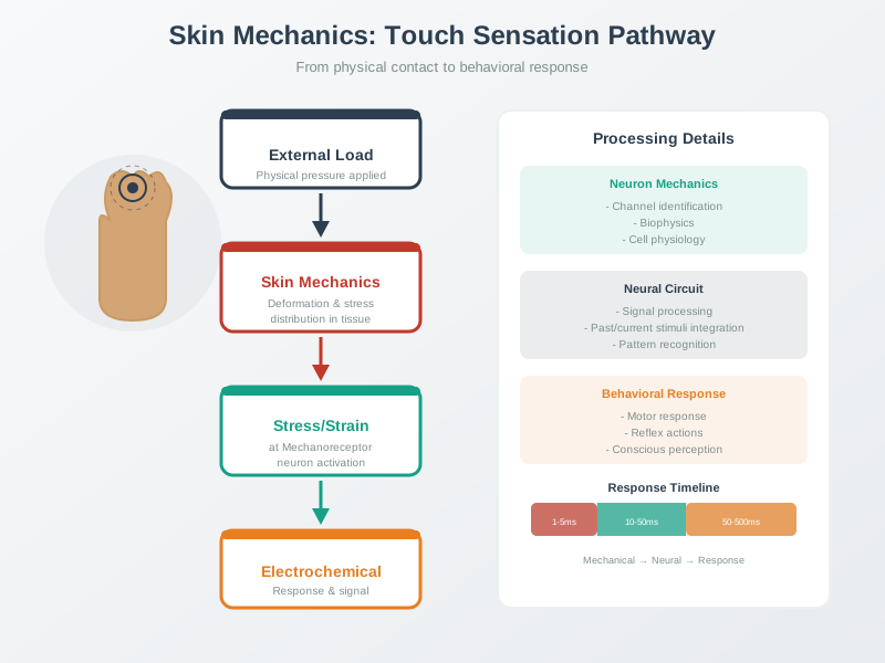
Intuition: a piezoelectric sensor is like a fingertip brushing a surface — it vividly feels the moment of contact and the texture as it moves, but it stops noticing a weight left resting on it. It senses change, not state.
Overview Knowledge Check
29.5 Charge Amplifier Basics
A piezoelectric element produces a charge proportional to the applied force, through its piezoelectric coefficient d:
Charge:  Q = d × F
  d = piezoelectric coefficient (charge per newton)
  quartz ≈ 2.3 pC/N,  PVDF polymer ≈ tens of pC/N,  PZT ≈ hundreds of pC/N
Charge amplifier:  Vout = -Q / Cf   (integrates charge onto a feedback capacitor Cf)
Worked example: a tap on a PVDF touch film
PVDF film with d ≈ 20 pC/N, a 10 N tap:
  Q = 20e-12 C/N × 10 N = 200 pC

That charge is far too small to read directly, so a
charge amplifier converts it to a voltage. With a
feedback capacitor Cf = 1 nF:
  Vout = Q / Cf = 200e-12 / 1e-9 = 0.20 V

A readable 0.2 V pulse marks the instant of the tap.
Note the output is a pulse, not a level. It appears as the force rises and disappears as the force settles, which is precisely the "event detector" character we want for tactile and vibration sensing.
Now check whether that pulse is large enough for the electronics. A 12-bit ADC over 3.3 V has a least-significant bit of about 3.3 / 4096 = 0.0008 V. The 0.20 V tap is roughly 250 counts, which is easy to threshold. A gentler 1 N tap would make about 20 pC and therefore 20 mV with the same 1 nF feedback capacitor, still about 25 ADC counts before noise and filtering. That is usable, but it leaves much less margin.
This is why Cf is a design knob rather than an arbitrary part. A smaller capacitor gives more voltage per newton but saturates sooner during hard impacts. A larger capacitor survives larger forces but shrinks the signal. If a gripper may see 1 N texture taps and 100 N accidental knocks, pick Cf so the small signal clears the ADC noise floor while the large signal stays below the input rail.
Why a charge amplifier, not a plain voltage buffer? A piezo element's own output voltage depends on cable capacitance, so it drifts with wiring. A charge amplifier reads the charge directly, making the reading independent of cable length — important for a sensor whose signal is measured in picocoulombs.
Practitioner Knowledge Check
29.6 No DC in Piezo Touch
The defining limitation of piezoelectric sensing — no response to steady force — comes straight from the physics of charge, and it is the same trade-off biology made.
Electrically, the piezo element behaves like a tiny charge source in parallel with its own capacitance and leakage resistance. When force changes, charge is displaced quickly and the amplifier sees a pulse. When force stops changing, no new charge is produced; the stored charge then leaks through the material and feedback path. The output therefore decays even if the mechanical load remains perfectly steady.
The feedback resistor and capacitor set the decay time. With Rf = 100 MΩ and Cf = 1 nF, the time constant is Rf × Cf = 0.1 s and the high-pass corner is about 1 / (2πRfCf) = 1.6 Hz. A 20 Hz vibration or tap passes well; a 0.1 Hz slow squeeze is strongly attenuated. Raising Rf or Cf moves the cutoff lower, but it also changes recovery time, noise, leakage sensitivity, and pulse amplitude.
Charge leaks away
The charge from a constant deformation slowly bleeds off through the material's finite insulation resistance and the amplifier input. So a held force gives a decaying pulse, not a steady level — piezo sensing is inherently AC-coupled.
The low-frequency cutoff
In a charge amplifier the feedback resistor sets a high-pass corner at fc = 1 / (2π Rf Cf). Below it the response rolls off, which is why piezo excels at vibration, impact, and sound but cannot weigh a static object.
Rapidly vs slowly adapting
Skin pairs rapidly adapting receptors (dynamic, like piezo) with slowly adapting ones (sustained pressure). A full biomimetic touch system likewise pairs piezoelectric films with a static-capable sensor such as a capacitive or resistive one.
Static touch partners
Held touch pressure can also come from tactile MEMS pressure tiles embedded in a compliant pad or from stretchable optical waveguides whose light path changes under pressure, strain, or curvature. Treat these as static or slow channels that complement the piezo event channel, not as replacements for its vibration evidence.
Cross-sensitivity to watch
PVDF is also pyroelectric, so it responds to temperature changes as well as force. Biomimetic designs must guard against a warm finger being mistaken for a press — a real cross-sensitivity, not a hypothetical one.
So the piezoelectric "weakness" is really a specialisation, and it is the same specialisation evolution chose for vibration-sensing receptors: report the change, ignore the constant. Building touch that feels both a tap and a resting weight means combining a dynamic piezoelectric sensor with a static-capable partner — exactly how skin does it. The validation test should therefore include both parts: a tap or vibration test to prove the dynamic channel, and a held-load test to prove the companion static channel.
Under-the-Hood Knowledge Check
29.7 Release Checklist
Before relying on a piezoelectric biomimetic touch channel, confirm these points:
- The product requirement is an event, tap, vibration, texture, or slip signal rather than a steady force by itself.
- The piezo material coefficient, force range, and feedback capacitor produce ADC counts above the noise floor without clipping hard impacts.
- The feedback resistor and capacitor set a low-frequency cutoff that passes the events of interest and rejects irrelevant drift.
- Cable capacitance, leakage, input bias current, and temperature cross-sensitivity are included in the validation plan.
- A static-capable capacitive, resistive, strain, or force channel exists when the system must know held pressure or weight.
- Validation includes both dynamic tap/vibration tests and held-load tests so the channel boundary is visible.
29.8 See Also
- Biomimetic Sensing for the broader receptor-role and hierarchical-processing design pattern.
- Sensor Circuit Fundamentals for the analog building blocks behind the readout path.
- Signal Conditioning for Sensors for amplification, filtering, and ADC preparation.
- Sensor Specifications for response time, bandwidth, range, and accuracy requirements.
29.9 Next
Return to Biomimetic Sensing once the dynamic touch channel is bounded, then continue to Sensor Specifications to translate the biomimetic role into measurable requirements.