2 How Sensors Work
2.1 Start With the Measurement Story
A learner is handed a temperature sensor and a dashboard that moves when the room changes. The useful first question is not how the code reads a pin, but what real-world change the sensor converts into evidence and how much trust that evidence deserves.

Phoebe’s Why
This chapter’s warning that “the last digits meaningless” is not only about the ADC – it starts one link earlier, at the transducer itself. A sensing element does not respond to a physical change instantly; heat has to diffuse through a thermistor’s bead, moisture has to migrate through a capacitive film, and that lag behaves like a low-pass filter with its own bandwidth. Firmware can only trust its sample rate against that bandwidth, not against an assumed number, because the transducer physically cannot produce a faster real signal than its own response time allows – and if the sample interval is slower than the transducer’s own bandwidth demands, a genuinely fast physical event, such as the brief airflow gust from the vent example below, folds down and disguises itself as ordinary slow drift. Only once that “condition to element” link is trusted does the ADC’s own resolution matter: an \(N\)-bit converter adds a fixed quantization floor no calibration can remove, and more digits only help if they sit above both the transducer’s own noise and that floor.
The Derivation
A first-order transducer’s response time \(\tau_{90}\) (time to reach 90% of a step change) sets an equivalent time constant and corner frequency:
\[\tau = \frac{\tau_{90}}{\ln 10}, \qquad f_c \approx \frac{1}{2\pi\tau}\]
Nyquist then applies to the transducer’s own bandwidth, not an assumed signal rate:
\[f_s \geq 2f_c\]
Quantization step and resulting dynamic range for an \(N\)-bit ADC over reference \(V_{ref}\), independent of the transducer entirely:
\[q = \frac{V_{ref}}{2^N}, \qquad \mathrm{SNR_{dB}} = 6.02N+1.76\]
Worked Numbers: A Catalog-Typical Humidity Element
- Transducer bandwidth: a catalog-typical capacitive humidity sensor with \(\tau_{90}=30\) s gives \(\tau = 30/\ln10\) \(= 13.0\) s \(\to f_c \approx 1/(2\pi\times13.0)\) \(= 0.0122\) Hz – a signal that physically cannot change faster than about once per 82 s
- The sampling floor this sets: Nyquist needs \(f_s \geq 0.0244\) Hz, i.e. a sample at least every \(41\) s – sample slower than that and a real fast event, like the vent-airflow gust named below, can alias into what looks like ordinary slow drift
- Where quantization enters separately: a catalog-typical \(10\)-bit ADC on a \(3.3\) V reference gives \(q = 3.3/1024\) \(= 3.22\) mV, \(\mathrm{SNR} = 6.02(10)+1.76\) \(= 62.0\) dB
- Turning the floor into a real-world limit: if the conditioning circuit scales the signal at a catalog-typical \(10\) mV per unit reading, the \(3.22\) mV quantization step alone limits resolution to about \(0.322\) units per code – before any accuracy, drift, or calibration error is added, which is exactly the gap this chapter’s “high-resolution reading” warning is pointing at
2.2 Overview: What a Sensor Claim Means
A sensor is the first evidence boundary between the physical world and an IoT system. It converts a physical, chemical, biological, or human-context condition into an electrical or digital signal that software can record. The useful claim is not "we have a temperature sensor" or "we have an accelerometer." The useful claim is that a named condition can be measured accurately enough, often enough, and reliably enough for a specific decision.
That boundary matters because a reading is not the same thing as truth. Placement, range, resolution, noise, drift, calibration, response time, interface behavior, power state, enclosure, and data interpretation all shape what the reading can prove. A sensor can be electrically connected and still provide weak evidence for the real-world decision.
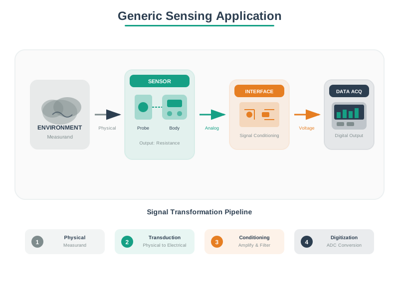
A useful first review therefore separates what is sensed from how it becomes data. The condition might be temperature, light, force, gas concentration, motion, distance, or touch. The transducer might change resistance, capacitance, voltage, current, frequency, pulse timing, or a digital register. The interface might amplify, filter, divide, excite, sample, timestamp, or validate the signal before the application ever sees a value.
That separation prevents common beginner mistakes. A dashboard can show stable numbers while the probe is mounted in the wrong airflow. A digital bus can return checksummed messages while the sensing element is saturated. A high-resolution ADC can report many digits while the reference voltage, calibration source, or enclosure makes the last digits meaningless. The sensor claim is only strong when the physical condition, conversion path, and decision boundary are reviewed together.
If you only need the intuition, this layer is enough: approve a sensor from the measurement decision and evidence boundary, not from the part name. Name what is measured, where it is measured, how it is converted, how it is calibrated, and what retest would be needed after a change.
The First Sensor Evidence Boundaries
Physical condition
State the condition, location, expected range, response speed, environment, and decision that will use the measurement.
Transducer and signal
Explain how the condition becomes voltage, current, resistance, capacitance, pulse timing, frequency, or a digital message.
Specification fit
Check range, resolution, accuracy, precision, repeatability, drift, response time, noise, interface, and power behavior against the requirement.
Evidence and operations
Record calibration, installation, validation, fault handling, maintenance owner, replacement rule, and retest trigger.
Beginner Examples
- A room temperature sensor near a vent may measure airflow effects more than room comfort.
- A digital sensor still needs evidence; a bus message can be valid while the physical placement is wrong.
- A high-resolution reading is not useful if accuracy, calibration, noise, or drift makes the last digits meaningless.
- A battery-powered sensor may trade sample rate, radio schedule, and heater use against lifetime and measurement quality.
Overview Knowledge Check
2.3 Evidence-Fit Sensor Selection
A practical sensor selection workflow starts with the decision that needs evidence. The sensor is then chosen because it can observe the needed condition under real installation constraints, not because it appears first in a parts list. The review should preserve the path from condition to transducer, signal conditioning, interface, firmware parsing, data quality checks, and downstream decision.
The most useful early artifact is a measurement record. It names the sensing goal, expected range, tolerated error, required response time, environment, power budget, interface, calibration method, and evidence source. It also names what the chosen sensor is not allowed to prove.
Selection Sequence
- Name the decision. State whether the reading supports display, logging, alerting, closed-loop control, diagnosis, billing, safety, or model input.
- Bound the physical condition. Record expected range, worst expected environment, installation location, response speed, and interfering conditions.
- Compare specifications. Check accuracy, precision, resolution, sensitivity, drift, response time, interface, power behavior, and operating limits against the requirement.
- Plan calibration and validation. Identify reference checks, installation checks, self-test behavior, maintenance interval, and failure indicators.
- Document unsupported claims. State conditions, placements, environments, or decisions that the chosen sensor has not proven.
Practitioner Knowledge Check
2.4 Measurement Chain Failure Limits
Under the hood, a sensor reading is a chain of transformations. A physical condition affects a sensing element. The sensing element produces a raw signal. Circuits condition that signal. An ADC, timer, counter, or digital interface captures it. Firmware scales and filters it. Software timestamps and stores it. The application interprets it. Each link can introduce error, delay, saturation, stale data, or unsupported meaning.
Good reviews keep those links separate. A stable I2C transaction does not prove the sensor is placed correctly. A precise ADC count does not prove the calibration reference is valid. A smooth dashboard chart does not prove the physical condition is changing smoothly. The evidence trail should say which link was proven and which claim remains unproven.
Failure Boundaries to Separate
- Physical boundary: placement, contact, airflow, light path, vibration, contamination, enclosure, self-heating, and environmental exposure.
- Transducer boundary: range, sensitivity, saturation, hysteresis, cross-sensitivity, drift, warm-up, and aging.
- Circuit boundary: excitation, reference voltage, impedance, filtering, shielding, grounding, cable length, and noise pickup.
- Interface boundary: ADC configuration, bus timing, address conflicts, missing acknowledgements, checksum behavior, stale registers, and parser errors.
- Application boundary: units, timestamps, filtering, thresholds, data quality flags, fault handling, and decision ownership.
Under-the-Hood Knowledge Check
2.5 Summary
- Sensor approval starts with a measurement claim, not with a readable value or part name.
- The review must connect physical condition, placement, transducer behavior, signal path, interface, firmware, data quality, and application decision.
- Accuracy, precision, resolution, drift, response time, range, calibration, and operating environment answer different questions and should not be collapsed into one score.
- Digital interfaces still need physical measurement evidence; communication success is not the same as sensing correctness.
- Every sensor claim needs an owner, calibration or validation method, fault behavior, unsupported-claim boundary, and retest trigger.
Approve a sensor only when the measured condition, conversion chain, specification fit, calibration evidence, operating owner, and retest boundary are explicit.
2.6 See Also
Sensor Specifications
Interpret range, accuracy, precision, resolution, response time, drift, noise, and calibration evidence.
Sensor Classifications
Classify sensors by measured quantity, output type, operating principle, interface, and evidence need.
Common Sensors and MEMS
Compare common devices by measured quantity, output, range, interface, calibration need, and IoT fit.
Sensor Selection Guide
Match sensing goals, environments, power, interface, calibration burden, and evidence needs to a sensor choice.